EP1460668A1 - Preassembled terminal assembly - Google Patents
Preassembled terminal assembly Download PDFInfo
- Publication number
- EP1460668A1 EP1460668A1 EP04006424A EP04006424A EP1460668A1 EP 1460668 A1 EP1460668 A1 EP 1460668A1 EP 04006424 A EP04006424 A EP 04006424A EP 04006424 A EP04006424 A EP 04006424A EP 1460668 A1 EP1460668 A1 EP 1460668A1
- Authority
- EP
- European Patent Office
- Prior art keywords
- connection
- contact
- heating device
- connection module
- heating
- Prior art date
- Legal status (The legal status is an assumption and is not a legal conclusion. Google has not performed a legal analysis and makes no representation as to the accuracy of the status listed.)
- Withdrawn
Links
Images
Classifications
-
- H—ELECTRICITY
- H05—ELECTRIC TECHNIQUES NOT OTHERWISE PROVIDED FOR
- H05B—ELECTRIC HEATING; ELECTRIC LIGHT SOURCES NOT OTHERWISE PROVIDED FOR; CIRCUIT ARRANGEMENTS FOR ELECTRIC LIGHT SOURCES, IN GENERAL
- H05B1/00—Details of electric heating devices
- H05B1/02—Automatic switching arrangements specially adapted to apparatus ; Control of heating devices
- H05B1/0202—Switches
- H05B1/0216—Switches actuated by the expansion of a solid element, e.g. wire or rod
-
- H—ELECTRICITY
- H01—ELECTRIC ELEMENTS
- H01H—ELECTRIC SWITCHES; RELAYS; SELECTORS; EMERGENCY PROTECTIVE DEVICES
- H01H37/00—Thermally-actuated switches
- H01H37/74—Switches in which only the opening movement or only the closing movement of a contact is effected by heating or cooling
- H01H37/76—Contact member actuated by melting of fusible material, actuated due to burning of combustible material or due to explosion of explosive material
- H01H37/764—Contact member actuated by melting of fusible material, actuated due to burning of combustible material or due to explosion of explosive material in which contacts are held closed by a thermal pellet
-
- H—ELECTRICITY
- H05—ELECTRIC TECHNIQUES NOT OTHERWISE PROVIDED FOR
- H05B—ELECTRIC HEATING; ELECTRIC LIGHT SOURCES NOT OTHERWISE PROVIDED FOR; CIRCUIT ARRANGEMENTS FOR ELECTRIC LIGHT SOURCES, IN GENERAL
- H05B3/00—Ohmic-resistance heating
- H05B3/02—Details
- H05B3/06—Heater elements structurally combined with coupling elements or holders
Abstract
Description
Die vorliegende Erfindung betrifft eine Anschlussbaugruppe für elektrische Heizeinrichtungen, insbesondere für Durchlauferhitzer gemäß dem Oberbegriff des Anspruchs 1 sowie eine hiermit ausgerüstete Heizeinrichtung gemäß dem Anspruch 10.The present invention relates to a connection module for electrical heating devices, in particular for instantaneous water heaters, and to a heating device equipped therewith according to
Elektrische Heizeinrichtungen werden beispielsweise in Form eines Durchlauferhitzers zum Erwärmen eines Arbeitsfluids, z. B. von Wasser, bei einer Arbeitsmaschine, wie einer Wasch- oder Geschirrspülmaschine, eingesetzt. Hierbei kann der wenigstens eine Heizleiter der Heizeinrichtung, der aus einem Material hergestellt ist, dessen elektrischer Widerstandswert zum Umwandeln von elektrischer Energie in Wärme ausreicht, um ein Durchflussrohr für das Arbeitsfluid spiralförmig herum gewickelt und, je nach verwendetem Heizleiter, auf geeignete Art und Weise an dem Durchflussrohr befestigt werden. Die beiden Enden des Heizleiters werden dabei in einer solchen Weise vorbereitet, dass nach einem Einbau der Heizeinrichtung in die Arbeitsmaschine ein Anschluss über geeignete Anschlusselemente an eine entsprechende Stromquelle erfolgen kann. 'Electric heaters are used, for example, in the form of a continuous-flow heater for heating a working fluid, e.g. B. of water, used in a machine such as a washing machine or dishwasher. Here, the at least one heating conductor of the heating device, which is made of a material whose electrical resistance value is sufficient for converting electrical energy into heat, can be spirally wound around a flow tube for the working fluid and, depending on the one used Heating conductor, are attached to the flow tube in a suitable manner. The two ends of the heating conductor are prepared in such a way that after installation of the heating device in the machine, a connection can be made to a corresponding power source via suitable connection elements. '
Um bei einem unbeabsichtigten Trockenlauf der Heizeinrichtung, d.h. bei einer Inbetriebnahme der Heizeinrichtung, ohne dass ein Arbeitsfluid durch das Durchflussrohr strömt, welches die von dem Heizleiter erzeugte Wärme abführen kann, eine Schädigung der Arbeitsmaschine zu verhindern, sind derartige Heizeinrichtungen mit Übertemperatursicherungen ausgestattet. Um einen insgesamt kompakten Aufbau dabei zu erzielen, wird angestrebt, die Übertemperatursicherung im Bereich der Anschlussenden des Heizleiters unterzubringen.In order to prevent the heating device from running dry accidentally, i.e. When the heating device is put into operation without a working fluid flowing through the flow tube, which can dissipate the heat generated by the heating conductor, to prevent damage to the working machine, such heating devices are equipped with excess temperature safeguards. In order to achieve an overall compact structure, the aim is to accommodate the overtemperature protection in the area of the connection ends of the heating conductor.
So ist beispielsweise aus der europäischen Patentanmeldung 0 727 799 eine derartige elektrische Heizeinrichtung mit Übertemperatursicherung bekannt, bei der ein Anschlussende des Heizleiters, der auf das Durchflussrohr unter Zwischenschaltung einer Isolierfolie direkt aufgewickelt ist, an einem auf das Durchflussrohr aufgesetzten Isolierkörper durch Hochbiegen eines Anschlussendes von dem Durchflussrohr befestigt ist. Daran schließt sich die Überlastsicherung an, welche als Schalter ausgebildet ist, der bei Erreichen einer Grenztemperatur die Stromzuführung zu dem Heizleiter unterbricht.For example, such an electrical heating device with overtemperature protection is known from European patent application 0 727 799, in which a connection end of the heating conductor, which is wound directly onto the flow tube with the interposition of an insulating film, on an insulating body placed on the flow tube by bending up one connection end of the Flow pipe is attached. This is followed by the overload protection, which is designed as a switch which interrupts the power supply to the heating conductor when a limit temperature is reached.
Die mittels eines Schweißvorganges erfolgende Befestigung des Anschlussendes des Heizleiters an dem Isolierkörper stellt eine arbeitsaufwendige Maßnahme dar, die zu erheblichen Kosten führt. Darüber hinaus bedarf es zusätzlicher Hilfs- bzw. Richtwerkzeuge, um den Isolierkörper und das Anschlussende während des Schweißvorganges in der jeweils vorgesehenen Position zu halten. Mit anderen Worten ist diese Lösung teuer, was insbesondere bei Bauteilen, die einem erheblichen Kostendruck unterliegen, von Nachteil ist.The attachment of the connection end of the heating conductor to the insulating body by means of a welding process is a labor-intensive measure which leads to considerable costs. In addition, additional auxiliary or straightening tools are required to hold the insulating body and the connection end in the intended position during the welding process. In other words, this solution is expensive, which is particularly disadvantageous for components which are subject to considerable cost pressure.
Es ist Aufgabe der vorliegenden Erfindung, eine Anschlussbaugruppe der eingangs genannten Art zu schaffen, die auf einfache und damit kostengünstige Weise einen Anschluss eines Heizleiters einer elektrischen Heizeinrichtung an einer Stromquelle ermöglicht. Darüber hinaus ist eine Heizeinrichtung vorzusehen, die eine derartige Anschlussbaugruppe verwendet.It is an object of the present invention to provide a connection module of the type mentioned at the outset, which enables a heating conductor of an electrical heating device to be connected to a power source in a simple and therefore inexpensive manner. In addition, a heating device is to be provided which uses such a connection module.
Die vorstehende Aufgabe wird hinsichtlich der Anschlussbaugruppe durch die Merkmale des Anspruchs 1 gelöst. In den sich daran anschließenden Unteransprüchen 2 bis 9 finden sich vorteilhafte Ausgestaltungen hierzu.The above object is achieved with regard to the connection module by the features of claim 1. In the subsequent subclaims 2 to 9 there are advantageous refinements for this.
Durch die Vormontage der Anschlussbaugruppe und durch den Berührungs- bzw. Anlagekontakt zwischen den Anschlussenden des Heizleiters und den Kontaktierungselementen besteht die Möglichkeit, auf einfache Weise bei der Montage den Anschluss der Heizeinrichtung an einer Stromquelle zu bewirken. Durch die Kontaktierung zwischen Anschlussbaugruppe und Anschlussenden des Heizleiters mittels einfacher Berührung bzw. Anlage bedarf es keiner abstehender Anschlussenden des Heizleiters und/oder komplizierter Bewegungen beim Anbringen der Anschlussbaugruppe, sondern es genügt eine einfache Bewegung in radialer Richtung des Durchflussrohres bzw. senkrecht zur Verlegungsebene des Heizleiters. Auch müssen keine mechanischen Widerstände wie bei Steckfahnen und dgl. überwunden werden.By pre-assembling the connection module and by the contact or system contact between the connection ends of the heating conductor and the contacting elements, it is possible to easily connect the heating device to a power source during assembly. Due to the contact between the connection module and the connection ends of the heating conductor by means of a simple touch or contact, no protruding connection ends of the heating conductor and / or complicated movements when attaching the connection module are required, but a simple movement in the radial direction of the flow tube or perpendicular to the laying plane of the heating conductor is sufficient , There is also no need to overcome mechanical resistances such as with flags and the like.
Darüber hinaus kann die Heizeinrichtung mit dem Durchflussrohr oder mit einer Trägerplatte, auf der der Heizleiter in einer Ebene verlegt ist, in einem eigenen Herstellvorgang getrennt von der Anschlussbaugruppe gefertigt und anschließend die beiden Baugruppen, d. h. die Heizeinrichtung als Heizbaugruppe und die Anschlussbaugruppe auf einfache Weise miteinander verbunden werden. Weiterhin besteht die Möglichkeit, bei einer fehlerhaften Anschlussbaugruppe diese auf einfache Weise zu ersetzen, was bei der vorstehend dargestellten Lösung des Standes der Technik nicht möglich ist, da sich das Anschlussende in Folge des eingesetzten Schweißvorganges von dem Isolierkörper nicht mehr trennen lässt.In addition, the heating device with the flow tube or with a support plate, on which the heating conductor is laid in one plane, can be manufactured separately from the connection module in a separate manufacturing process and then the two modules, ie the heating device as heating module and the connection module, can be easily connected to one another get connected. Furthermore, there is the possibility of replacing a defective connection module in a simple manner, which is not possible with the solution of the prior art described above, since the connection end can no longer be separated from the insulating body as a result of the welding process used.
Grundsätzlich kann die Anschlussbaugruppe nach dem Aufsetzen auf der Heizeinrichtung zur Herstellung eines Kontaktes zwischen den Anschlussenden des Heizleiters und den beiden Kontaktierungselementen der Anschlussbaugruppe unlösbar mit der Heizeinrichtung gegebenenfalls mittels geeigneter Befestigungselemente verbunden werden. Ebenso ist es möglich, dass die Anschlussbaugruppe ebenfalls mittels geeigneter Befestigungselemente, wie Klammern, Schellen usw. lösbar an der Heizeinrichtung angebracht ist. Beispielsweise können hierzu Nasen an der Trägereinheit angebracht oder angeformt sein, welche über Spannbügel mit der Heizeinrichtung verbunden sind. Nach Aufsetzen der Anschlussbaugruppe auf der Heizeinrichtung wird hierdurch die Anschlussbaugruppe gegen die Heizeinrichtung gezogen, so dass die vorzugsweise vorhandene Kontaktfläche des ersten Kontaktierungselementes und die gegebenenfalls vorhandene Kontaktfläche des zweiten Kontaktierungselementes in flächige Anlage zu den Anschlusselementen des Heizleiters gelangt.Basically, the connection module can be connected permanently to the heating device, if necessary by means of suitable fastening elements, after it has been placed on the heating device in order to make contact between the connection ends of the heating conductor and the two contacting elements of the connection module. It is also possible that the connection module is also detachably attached to the heating device by means of suitable fastening elements, such as clips, clamps, etc. For example, lugs can be attached or formed on the carrier unit for this purpose, which are connected to the heating device via clamping brackets. After the connection module has been placed on the heating device, the connection module is thereby pulled against the heating device, so that the contact surface of the first contacting element, which is preferably present, and the contact surface, if any, of the second contacting element comes into flat contact with the connection elements of the heating conductor.
Weiterhin ist es möglich, an der Heizeinrichtung einen oder mehrere Bolzen, beispielsweise durch Schweißen, anzubringen, die mit oder ohne ein Gewinde dazu dienen, die Anschlussbaugruppe an der Heizeinrichtung zu befestigen. Im Falle von Bolzen mit Gewinde kann das Anbringen der Anschlussbaugruppe dadurch erfolgen, dass diese Durchgangsdurchbrechungen beziehungsweise durchgehende Ausnehmungen aufweist, mittels denen die Anschlussbaugruppe auf die Bolzen aufgeschoben werden kann. Anschließend können Muttern auf die Bolzen aufgeschraubt werden, so dass die Anschlussbaugruppe an der Heizeinrichtung gehalten ist. Weisen die Bolzen kein Gewinde auf, so können die Ausnehmungen Rastnasen, clipsähnliche Elemente usw. zum lösbaren oder unlösbaren Verrasten der Anschlussbaugruppe an der Heizeinrichtung zu ermöglichen.Furthermore, it is possible to attach one or more bolts, for example by welding, to the heating device, which, with or without a thread, serve to fasten the connection module to the heating device. In the case of threaded bolts, the connection module can be attached by having through openings or continuous recesses by means of which the connection module can be pushed onto the bolts. Then nuts can be screwed onto the bolts so that the connection module is held on the heating device. If the bolts do not have a thread, the recesses can allow latching lugs, clip-like elements etc. for releasable or non-releasable latching of the connection module on the heating device.
Um eine sichere Kontaktierung des ersten und/oder des zweiten Kontaktierungselementes an den Anschlussenden des Heizleiters der Heizeinrichtung sicherzustellen, kann weiterhin vorgesehen sein, dass das erste und/oder das zweite Kontaktierungselement elastisch federnd in Kontaktierungsrichtung an der Trägereinheit gehalten ist. Wird die Anschlussbaugruppe auf die Heizeinrichtung aufgesetzt, so werden das erste und/oder das zweite Kontaktierungselement in Folge ihrer elastisch federnden Ausbildung in Kontaktierungsrichtung gegen das jeweilige Anschlussende des Heizleiters der Heizeinrichtung gedrängt. Sofern das erste und/oder das zweite Kontaktierungselement über die Außenkontur der Trägereinheit im nicht-montierten Zustand der Anschlussbaugruppe hinausragen, wird darüber hinaus dem ersten und/oder dem zweiten Kontaktierungselement beim Aufsetzen der Anschlussbaugruppe auf die Heizeinrichtung eine Vorspannung aufgeprägt. Diese Vorspannung kann darüber hinaus noch in der Weise unterstützt werden, dass auf das erste und/oder das zweite Kontaktierungselement eine Feder, wie z. B. eine Blattfeder, einwirkt oder das erste und/oder das zweite Kontaktierungselement eine aufgeprägte Eigenspannung aufweisen. Schließlich besteht noch die Möglichkeit, dass das erste und/oder das zweite Kontaktierungselement über einen elektrisch leitfähigen, stromtragfähigen Kunststoff in Kontaktrichtung vorgespannt sind.In order to ensure reliable contacting of the first and / or the second contacting element at the connection ends of the heating conductor of the heating device, it can further be provided that the first and / or the second contacting element resiliently in the contacting direction the carrier unit is held. If the connection module is placed on the heating device, the first and / or the second contacting element are urged against the respective connection end of the heating conductor of the heating device as a result of their elastically resilient design in the contacting direction. If the first and / or the second contacting element protrude beyond the outer contour of the carrier unit in the non-assembled state of the connection assembly, a preload is also applied to the first and / or the second contacting element when the connection assembly is placed on the heating device. This bias can also be supported in such a way that on the first and / or the second contacting element, a spring such. B. a leaf spring, acts or the first and / or the second contacting element have an impressed internal stress. Finally, there is also the possibility that the first and / or the second contacting element are prestressed in the contact direction via an electrically conductive, current-carrying plastic.
Darüber hinaus wird durch eine flächige Anlage des ersten und/oder des zweiten Kontaktierungselementes sichergestellt, dass eine ausreichende elektrische Verbindung bzw. Kontaktierung zwischen der Anschlussbaugruppe und damit der Stromquelle sowie dem Heizleiter ermöglicht wird.In addition, a flat contact of the first and / or the second contacting element ensures that a sufficient electrical connection or contact is made possible between the connection module and thus the power source and the heating conductor.
Hinsichtlich der temperaturabhängigen Überlastsicherung besteht prinzipiell die Möglichkeit, dass diese an einem beliebigen Ort der Heizeinrichtung angebracht wird, solange sichergestellt ist, dass bei einem Auslösen der Überlastsicherung eine Unterbrechung des Stromflusses bewirkt wird. Ebenfalls besteht die Möglichkeit, dass die temperaturabhängige Überlastsicherung an der Anschlussbaugruppe vorgesehen wird. Eine besonders kompakte und montagefreundliche Bauweise wird dadurch realisiert, dass die temperaturabhängige Überlastsicherung in den Stromfluss zwischen der Kontaktfläche des ersten Kontaktierungselementes und dem Anschlussabschnitt geschaltet ist. Selbstverständlich kann die temperaturabhängige Überlastsicherung auch in den Stromfluss zwischen dem zweiten Kontaktierungselement und dem Anschlussabschnitt vorgesehen sein.With regard to the temperature-dependent overload protection, there is in principle the possibility of attaching it to any location in the heating device, as long as it is ensured that the current flow is interrupted when the overload protection is triggered. There is also the possibility that the temperature-dependent overload protection is provided on the connection module. A particularly compact and easy-to-assemble design is realized in that the temperature-dependent overload protection is connected to the current flow between the contact surface of the first contacting element and the connection section. Of course, the temperature-dependent overload protection can also be used in the current flow between the second contacting element and the connection section can be provided.
Für die temperaturabhängige Überlastsicherung können alle geeigneten Maßnahmen, die eine Unterbrechung des Stromflusses bei Auslösen der Überlastsicherung realisieren, vorgesehen werden. Eine einfache und zuverlässige temperaturabhängige Überlastsicherung kann aus einem vorgespannten Federstreifen bestehen, der an seinem einen Ende mit dem Anschlussabschnitt und an seinem anderen Ende über ein Verbindungsmittel mit der Kontaktfläche des ersten Kontaktierungselementes in der Weise verbunden ist, dass bei Erreichen eines vorbestimmten Temperaturbereiches, vorzugsweise einer vorbestimmten Grenztemperatur das Verbindungsmittel den vorgespannten Federstreifen freigibt und dieser von der Kontaktfläche abhebt. Als Verbindungsmittel kann hierbei jedes Material eingesetzt werden, beispielsweise ein geeignetes niedrigschmelzendes Lot, welches auf den jeweiligen Anwendungsfall dimensioniert ist. Darüber hinaus ist auch ein bei einer definierten Temperatur oder in einem engen Temperaturbereich erweichendes oder schmelzendes Kontaktmaterial verwendbar.All suitable measures for interrupting the current flow when the overload protection is triggered can be provided for the temperature-dependent overload protection. A simple and reliable temperature-dependent overload protection can consist of a prestressed spring strip, which is connected at one end to the connection section and at its other end via a connecting means to the contact surface of the first contacting element in such a way that when a predetermined temperature range is reached, preferably one predetermined limit temperature, the connecting means releases the prestressed spring strip and lifts it from the contact surface. Any material can be used as the connecting means, for example a suitable low-melting solder, which is dimensioned for the respective application. In addition, a contact material softening or melting at a defined temperature or in a narrow temperature range can also be used.
Im funktionsgemäßen Betrieb der Heizeinrichtung bleibt die Temperatur an dem Verbindungsmittel unterhalb der bestimmungsgemäßen Grenztemperatur bzw. des bestimmungsgemäßen Temperaturbereiches. Je nach Auslegung des Verbindungsmittels muss hierbei ein gewisser Temperatursicherheitsabstand berücksichtigt werden, damit durch die betriebsgemäße Temperaturwechselbeanspruchung keine vorzeitige Ablösung des vorgespannten Federstreifens in Folge der ständig einwirkenden Zugspannung bzw. Zugkraft auftritt. Im Störungsfall, der, wie bereits dargelegt, durch mangelhafte Wärmeabfuhr an der Heizeinrichtung entstehen kann, kommt es im Bereich des Verbindungsmittels zu einer Erwärmung, welche das Verbindungsmittel in der Weise "erweichen" lässt, dass die auf die Lotstelle einwirkenden Zugkraft bzw. Zugspannung ausreicht, den Federstreifen von der Lotstelle zu trennen. Der Federstreifen kann sich daher in Folge seiner ihm aufgeprägten Vorspannung, sei es mittels einer Blattfeder oder mittels einer aufgeprägten Eigenspannung, von der Kontaktfläche des ersten Kontaktierungselementes lösen und damit den elektrischen Kontakt zwischen der Stromquelle und dem Heizleiter unterbrechen. Die sich hierbei ausbildende Trennstrecke muss so groß sein, dass es zu keiner neuerlichen Zündung des Lichtbogens kommen kann. Bei einem Einsatz in Gleichspannungsnetzen können für die Löschung des entstehenden Lichtbogens in Abhängigkeit der Betriebsspannung zusätzliche Funkenlöschmaßnahmen eingesetzt werden. Das zweite Kontaktierungselement kann auch über einen elektrisch leitfähigen, stromtragfähigen Kunststoff in Kontaktrichtung vorgespannt sein.In the functional operation of the heating device, the temperature at the connecting means remains below the intended limit temperature or the intended temperature range. Depending on the design of the connecting means, a certain temperature safety margin must be taken into account so that the operational temperature change stress does not lead to premature detachment of the pretensioned spring strip as a result of the constantly acting tensile stress or tensile force. In the event of a malfunction, which, as already explained, can result from inadequate heat dissipation from the heating device, heating occurs in the area of the connecting means, which "softens" the connecting means in such a way that the tensile force or tensile stress acting on the solder point is sufficient to separate the spring strip from the solder joint. The spring strip can therefore, as a result of its pre-stressed on it, be it by means of a leaf spring or by means of an impressed internal stress, detach from the contact surface of the first contacting element and thus interrupt the electrical contact between the power source and the heating conductor. The separation gap that forms here must be so large that the arc cannot be ignited again. When used in DC voltage networks, additional spark extinguishing measures can be used to extinguish the resulting arc depending on the operating voltage. The second contacting element can also be biased in the contact direction via an electrically conductive, current-carrying plastic.
Die temperaturabhängige Überlastsicherung kann auch dadurch gebildet sein, dass ein vorzugsweise sich senkrecht zu der Längsachse der Heizeinrichtung erstreckendes Bewegungselement vorgesehen ist, das an seinem einem Ende in Berührungskontakt mit dem ersten Kontaktierungselement und an seinem anderen Ende über ein Formänderungselement, welches bei Einwirkung von Wärme seine Form ändern kann, mit der Heizeinrichtung in Kontakt steht, wobei die Länge des Bewegungselementes so bemessen ist, dass bei normalen Betrieb der elektrischen Heizeinrichtung das erste Kontaktierungselement in elektrischer Verbindung mit dem zugehörigen Anschlusselement des Anschlussabschnitts steht bzw. das Bewegungselement das erste Kontaktierungselement in elektrische Verbindung zu dem zugehörigen Anschlusselement des Anschlussabschnitts drängt.The temperature-dependent overload protection can also be formed in that a movement element, preferably extending perpendicular to the longitudinal axis of the heating device, is provided, which is in contact at one end with the first contacting element and at its other end via a deformation element which is exposed to heat Can change shape, is in contact with the heating device, the length of the movement element is dimensioned such that, during normal operation of the electrical heating device, the first contacting element is in electrical connection with the associated connection element of the connection section or the movement element is in electrical connection with the first contacting element urges to the associated connection element of the connection section.
Das Formänderungselement kann dabei ein Lottopf sein, in dem das Bewegungselement teilweise eintaucht und der mit einem Lot gefüllt ist, welches bei Überschreiten einer vorbestimmten Grenztemperatur erweicht, so dass das Bewegungselement weiter in den Lottopf eintauchen kann.The deformation element can be a solder pot, in which the movement element is partially immersed and which is filled with a solder, which softens when a predetermined limit temperature is exceeded, so that the movement element can further immerse into the solder pot.
Das Bewegungselement kann wiederum ein Keramikstab oder ein anderes Element, das elektrisch isolierend und vorzugsweise schlecht wärmeleitend ist, sein.The movement element can in turn be a ceramic rod or another element that is electrically insulating and preferably poorly heat-conducting.
Um insgesamt eine sichere Kontaktierung vorsehen zu können, ist es weiterhin vorteilhaft, wenn neben dem ersten Kontaktierungselement auch das zweite Kontaktierungselement im montierten Zustand der Anschlussbaugruppe an der Heizeinrichtung unter Vorspannung an dem Heizleiter, insbesondere an dem Anschlussende des Heizleiters, anliegt. Hierbei kann das zweite Kontaktierungselement durch eine in Richtung des Kontaktes mit dem Heizleiter vorspannende Blattfeder beaufschlagt sein. Ebenso besteht die Möglichkeit, dass das zweite Kontaktierungselement in Richtung des Kontaktes mit dem Heizleiter durch eine ihm aufgeprägte Eigenspannung vorgespannt ist.In order to be able to provide reliable contacting overall, it is furthermore advantageous if, in addition to the first contacting element, the second Contacting element in the assembled state of the connection module on the heating device under prestress on the heating conductor, in particular on the connection end of the heating conductor. In this case, the second contacting element can be acted upon by a leaf spring that prestresses in the direction of contact with the heating conductor. There is also the possibility that the second contact element is biased in the direction of contact with the heating conductor by an internal stress impressed on it.
Neben der temperaturabhängigen Überlastsicherung kann darüber hinaus eine Messeinheit vorgesehen sein, welche zur Steuerung der Heizeinrichtung dient. Diese Messeinheit kann getrennt von der Trägereinheit vorgesehen sein, sollte aber vorzugsweise an der Trägereinheit angeordnet sein. Hierbei besteht die Möglichkeit, dass die Messeinheit einstückig mit der Trägereinheit ausgebildet ist. Ebenso kann die Messeinheit an der Trägereinheit, vorzugsweise reversibel anbringbar sein. Sowohl die erste als auch die zweite Alternative erlauben wieder einen einfachen Montagevorgang, da die Anschlussbaugruppe mit der Messeinheit vormontiert werden kann.In addition to the temperature-dependent overload protection, a measuring unit can also be provided, which is used to control the heating device. This measuring unit can be provided separately from the carrier unit, but should preferably be arranged on the carrier unit. There is the possibility here that the measuring unit is formed in one piece with the carrier unit. Likewise, the measuring unit can preferably be reversibly attachable to the carrier unit. Both the first and the second alternative again allow a simple assembly process, since the connection module can be preassembled with the measuring unit.
Die Messeinheit kann unterschiedlich aufgebaut sein. So besteht beispielsweise die Möglichkeit, dass die Messeinheit ein Temperaturmesselement und ein vorzugsweise in Kontaktrichtung vorgespanntes Kontaktelement enthält, die über einen Anschlussabschnitt der Messeinheit mit einer Steuereinrichtung für die Heizeinrichtung verbindbar sind.The measuring unit can be constructed differently. For example, there is the possibility that the measuring unit contains a temperature measuring element and a contact element, preferably biased in the contact direction, which can be connected to a control device for the heating device via a connecting section of the measuring unit.
Um eine sichere Temperaturerfassung zu gewährleisten, kann weiterhin vorgesehen sein, dass das Temperaturerfassungselement gegenüber der Oberfläche der Heizeinrichtung und gegenüber dem Heizleiter elektrisch isoliert ist. Letzteres ist insbesondere dann erforderlich, wenn das Durchflussrohr bzw. die Trägerplatte für den Heizleiter geerdet ist.In order to ensure reliable temperature detection, it can further be provided that the temperature detection element is electrically insulated from the surface of the heating device and from the heating conductor. The latter is particularly necessary when the flow tube or the support plate for the heating conductor is grounded.
Als Temperaturmesselement kann beispielsweise ein in Kontaktrichtung elastisch federnd ausgebildeter NTC-Fühler vorgesehen sein. Ebenso besteht die Möglichkeit, dass das Temperaturmesselement eine glasgekapselte NTC-Pille mit einer Hülse aus einem gut wärmeleitenden Material ist.For example, an NTC sensor that is elastically resilient in the contact direction can be provided as the temperature measuring element. There is also the Possibility that the temperature measuring element is a glass-encapsulated NTC pill with a sleeve made of a good heat-conducting material.
Um einen einfachen Anschluss der Heizeinrichtung über die Anschlussbaugruppe an einer Stromquelle zu ermöglichen, ist es weiterhin von Vorteil, wenn der Anschlussabschnitt für jede Verbindung eine elektrische Steckeinrichtung, insbesondere eine Steckfahne aufweist. Mit anderen Worten sind also zwei Steckfahnen für die Verbindung der beiden Heizleiterenden mit der Stromquelle und bei Vorhandensein einer Messeinheit zwei weitere Steckfahnen für die Verbindung mit der Steuereinrichtung vorzusehen.In order to enable a simple connection of the heating device to a power source via the connection module, it is also advantageous if the connection section has an electrical plug-in device, in particular a plug-in lug, for each connection. In other words, two plug-in lugs for the connection of the two heating conductor ends to the power source and, if a measuring unit is present, two further plug-in lugs for the connection to the control device are to be provided.
Die Trägereinheit kann aus jedem temperaturbeständigen, elektrisch isolierenden Material bestehen. Bevorzugt wird für die Trägereinheit ein temperaturbeständiger Kunststoff oder eine Keramik gewählt.The carrier unit can consist of any temperature-resistant, electrically insulating material. A temperature-resistant plastic or ceramic is preferably selected for the carrier unit.
Damit die Trägereinheit sicher an der Heizeinrichtung angebracht werden kann, ist es weiterhin von Vorteil, wenn die Trägereinheit an Ihrer zu der Heizeinrichtung weisenden bzw. an der in Kontakt mit der Heizeinrichtung gelangenden Seite mit einer Außenkontur versehen ist, die komplementär zu der Außenkontur der Heizeinrichtung ist.So that the carrier unit can be securely attached to the heating device, it is furthermore advantageous if the carrier unit is provided on its side facing the heating device or on the side that comes into contact with the heating device with an outer contour that is complementary to the outer contour of the heating device is.
Hinsichtlich der Heizeinrichtung wird die vorstehende Aufgabe durch die Merkmale des Anspruchs 7 gelöst. Die Ansprüche 8 bis 10 enthalten vorteilhafte Ausgestaltungen hierzu. Insbesondere bei der Verwendung einer Heizeinrichtung, bei der der Heizleiter ein Dickschichtheizleiter ist, der unmittelbar auf einer Trägerplatte oder einem Trägerrohr aufgebracht wird, stellt die erfindungsgemäße Anschlussbaugruppe eine vorteilhafte Lösung dar.With regard to the heating device, the above object is achieved by the features of claim 7. Claims 8 to 10 contain advantageous refinements for this. In particular when using a heating device in which the heating conductor is a thick-film heating conductor which is applied directly to a carrier plate or a carrier tube, the connection module according to the invention represents an advantageous solution.
Weitere vorteilhafte Ausgestaltungen sowie Ausführungsbeispiele der erfindungsgemäßen Anschlussbaugruppe sowie der Heizeinrichtung gemäß der Erfindung werden nachstehend anhand der Zeichnungsfiguren erläutert. In diesem Zusammenhang ist darauf hinzuweisen, dass sich die bei der Beschreibung der Ausführungsbeispiele verwendeten Begriffe "oben", "unten", "links" und "rechts" auf die Zeichnungsfiguren mit normal lesbaren Bezugszeichen und Figurenbezeichnungen beziehen. Weiterhin ist darauf hinzuweisen, dass in den Zeichnungsfiguren funktionsgleiche und/oder geometrisch gleiche Bauteile mit gleichen Bezugszeichen versehen sind. Im einzelnen ist:
- Fig. 1
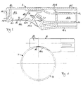
- eine Draufsicht von der Seite auf ein erstes Ausführungsbeispiel einer erfindungsgemäßen Anschlussbaugruppe, die auf eine Heizeinrichtung gemäß der Erfindung aufgesetzt ist;
- Fig. 2
- eine Längsschnittansicht der in Fig. 1 gezeigten Anschlussbaugruppe im vergrößerten Maßstab;
- Fig. 3
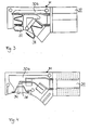
- eine Längsschnittansicht einer zweiten Ausführungsform der Anschlussbaugruppe gemäß der Erfindung;
- Fig. 4
- eine Längsschnittansicht einer dritten Ausführungsform der Anschlussbaugruppe gemäß der Erfindung; und
- Fig. 5
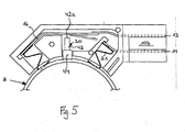
- eine Längsschnittansicht einer vierten Ausführungsform der Anschlussbaugruppe gemäß der Erfindung, bei der die Überlastsicherung ausgelöst hat.
- Fig. 1
- a plan view from the side of a first embodiment of a connection assembly according to the invention, which is placed on a heating device according to the invention;
- Fig. 2
- a longitudinal sectional view of the connector assembly shown in Figure 1 on an enlarged scale.
- Fig. 3
- a longitudinal sectional view of a second embodiment of the connector assembly according to the invention;
- Fig. 4
- a longitudinal sectional view of a third embodiment of the connector assembly according to the invention; and
- Fig. 5
- a longitudinal sectional view of a fourth embodiment of the connection module according to the invention, in which the overload protection has triggered.
Die in Fig. 1 gezeigte erfindungsgemäße Anschlussbaugruppe A ist bei einem Durchlauferhitzer H zum Erhitzen eines Mediums, wie beispielsweise das Waschwasser für eine Spülmaschine eingesetzt, der ein aus einem gut wärmeleitenden, aber korrosionsbeständigen Material hergestelltes Durchflussrohr D mit einem im wesentlichen kreisförmigen Querschnitt und einen nicht weiter dargestellten Heizleiter aus einem elektrischen Widerstandsmaterial umfasst. Der eine Heizschleife bildende Heizleiter ist wendelförmig um das Durchflussrohr D in der Weise gewickelt, dass er sich annährend über die gesamte axiale Länge des Durchflussrohres D erstreckt. Die beiden ebenfalls nicht dargestellten Anschlussenden des Heizleiters die in Umfangsrichtung hintereinander angeordnet sind, befinden sich dabei in der Nähe des einen stirnseitigen Endes des Durchflussrohres D, wogegen der äußerste Punkt der Schleife an dem anderen stirnseitigen Ende des Rohres D angeordnet ist. Zwischen dem Heizleiter und der Außenoberfläche des Durchflussrohres D ist eine ebenfalls nicht dargestellte, elektrisch isolierende, aber gut wärmeleitende Schicht bzw. Folie vorgesehen, die das Durchflussrohr D und damit das zu erwärmende Medium elektrisch von dem Heizleiter isoliert. Der Heizleiter ist in der Dickschichttechnik auf die isolierende Schicht aufgebracht.The connection assembly A according to the invention shown in FIG. 1 is used in a continuous-flow heater H for heating a medium, such as the washing water for a dishwasher, which has a flow tube D made of a good heat-conducting but corrosion-resistant material with an essentially circular cross section and one which is not heating conductor shown further comprises an electrical resistance material. The heating conductor forming a heating loop is helically wound around the flow tube D in such a way that it extends approximately over the entire axial length of the flow tube D. The two connection ends of the heating conductor, also not shown, which are arranged one behind the other in the circumferential direction, are located in the vicinity of one end of the flow tube D, whereas the outermost point of the loop is arranged at the other end of the tube D. Between the heating conductor and the outer surface of the flow tube D there is also provided an electrically insulating, but good heat-conducting layer or film, which is also not shown and which electrically insulates the flow tube D and thus the medium to be heated from the heating conductor. The heating conductor is applied to the insulating layer in thick-film technology.
Die Anschlussbaugruppe A weist ein quaderförmiges Gehäuse 10 auf, das eine Trägereinheit bildet und das aus einem wärmebeständigen und elektrisch isolierenden Material, vorzugsweise aus einem derartige Eigenschaften aufweisenden Kunststoff hergestellt ist. Das Gehäuse 10 besitzt an seiner unteren linken Außenseite, d.h. an der im montierten Zustand in Kontakt mit dem Heizleiter bzw. dem Durchflussrohr D kommenden Außenseite, einen kreissegmentbogenförmigen Anlageabschnitt 10a, dessen Kontur der Außenkontur des Durchflussrohres D entspricht bzw. zu dieser komplementär ist, wie dies insbesondere aus Fig. 1 hervorgeht. Darüber hinaus ist das Gehäuse 10 mit einem ersten und einem zweiten Hohlraum 10b und 10c versehen, die durch eine Vertikalwand 10d, welche sich von der unteren Außenwand 10e bis zu der oberen Außenwand 10f erstreckt, voneinander getrennt sind. Es ist noch zu bemerken, dass die übrigen Außenkonturen des Gehäuses 10 der Anschlussbaugruppe A entsprechend den weiteren Anforderungen ge-staltet sein können.The connection module A has a
Der erste Hohlraum 10b bildet einen Anschlussabschnitt zum Verbinden der Anschlussbaugruppe A mit einer nicht weiter dargestellten Stromquelle, wogegen der zweite Hohlraum 10c ein Kontaktierungsabschnitt zum Kontaktieren der Anschlussenden des Heizleiters ist. In dem an der Stirnseite, d.h. nach rechts offenen ersten Hohlraum 10b sind zwei flache Steckkontakte bzw. Steckfahnen 12, 14 übereinander angeordnet, auf die jeweils eine Verbindungsleitung zu der Stromquelle aufschiebbar ist. Die beiden Steckkontakte 12, 14 besitzen dabei eine Breite, die sehr viel größer als die Höhe der Kontakte 12, 14 ist. Wie insbesondere aus Fig. 2 hervorgeht, ist die axiale Länge der beiden Steckkontakte 12, 14 in dem ersten Hohlraum 10b kürzer als die axiale Länge des ersten Hohlraums 10b. Hierdurch erfolgt die Kontaktierung zwischen den Steckkontakten 12, 14 einerseits und den Verbindungsleitungen zu der Stromquelle andererseits im Inneren des Hohlraums 10b, so dass die Kontaktierungsstellen gegen Beschädigungen von außen geschützt sind und die Entstehung von Kurzschlüssen vermieden ist.The
Die beiden Steckkontakte 12, 14 durchsetzen die Vertikalwand 10d und erstrecken sich in den zweiten Hohlraum 10c. Dabei ist der obere Steckkontakt 12 durch ein geeignetes Befestigungsmittel, wie beispielsweise einen Niet, an der Innenseite der oberen Gehäusewand 10f angebracht. Der untere Steckkontakt 14 ist demgegenüber an einem von dem Anlageabschnitt 10a des Gehäuses 10 in das Innere des zweiten Hohlraumes 10c ragenden Wandfortsatz 10g, beispielsweise ebenfalls durch einen Niet, angebracht.The two
Links von dem Wandfortsatz 10g ist eine Aufnahme für ein Kontaktelement 16 vorgesehenen. Die Aufnahme wird durch zwei Nasen 10h, 10i gebildet, von denen sich die eine Nase 10h von dem Wandfortsatz 10g nach links und die andere von dem linken stirnseitigen Ende 10j des Gehäuses 10 nach rechts, jeweils parallel zu der oberen Gehäusewand 10f, erstreckt. Wie aus Fig. 2 hervorgeht, stehen die beiden Nasen 10h, 10i nicht über die Kontur des Anlageabschnitts 10a des Gehäuses 10 über, sondern ragen in den zweiten Hohlraum 10c hin. An ihren nach unten bzw. nach außen weisenden unteren Nasenflächen ist ein Kontaktelement oder ein erstes Kontaktierungselement 16 vorgesehen, das über eine Zugkraft in Folge der Federkraft eines nachstehend näher erläuterten Federstreifens 18 in die Taschen 10i, 10h gezogen und dort gehalten ist. Das Kontaktelement 16, dessen Breite ebenfalls sehr viel größer ist als seine Höhe und das die beiden Nasen 10h, 10i wie eine Brücke miteinander verbindet, durchschneidet dabei die kreisbogenförmige Kontur des Anlageabschnitts 10a in der Form einer Sekante und verläuft in dem nicht-montierten Zustand der Anschlussbaugruppe A parallel zu der oberen Gehäusewand 10f. Durch die sekantenartige Anordnung des Kontaktelements 16 wird dieses beim Aufsetzen der Anschlussbaugruppe A auf das Durchflussrohr D nach Innen gebogen, so dass ein flächige Anlage bzw. Berührung des Kontaktelements 16 mit dem zugehörigen Anschlussende des Heizleiters in Folge der Elastizität des Kontaktelements 16 unter Vorspannung erfolgt. In Fig. 1 ist die Überschneidung des Kontaktelements 16 mit der Wand des Durchflussrohres D gezeigt, d.h. das Maß der Verschiebung des Kontaktelements 16 in das Innere des zweiten Hohlraumes 10c beim Aufsetzen der Anschlussbaugruppe A auf das Durchflussrohr D.A receptacle for a
Zwischen dem an der Innenseite der oberen Gehäusewand 10f angebrachten Ende des oberen Steckkontaktes 12 und der in den Hohlraum 10c weisenden Fläche des Kontaktelements 16 ist der die Form eines invertierten Buchstabens "Z" aufweisender Federstreifen 18 vorgesehen. Das eine oder untere Ende des Federstreifens 18 ist an dem Kontaktelement mittels eines Lotmaterials vorzugsweise in Form eines Lotpunktes befestigt, wogegen das andere oder obere Ende an der nach Innen weisenden Seite des oberen Steckkontaktes 12, beispielsweise mittels des den oberen Steckkontakt an der oberen Gehäusewand 10f befestigenden Niet angebracht ist. Das verwendete Lotmaterial zum Anbringen des unteren Endes des Federstreifens 18 an dem Kontaktelement 16 ist dabei so ausgewählt, dass bei Erreichen eines vorgegebenen Temperaturbereiches, vorzugsweise einer vorbestimmten Grenztemperatur das Lotmaterial weich wird und sich der Federstreifen 18 von dem Kontaktelement 16 lösen kann. Der Federstreifen 18 ist dabei so vorgespannt, dass er bei Nicht-Anbringung an dem Kontaktelement 16 in das Innere des zweiten Hohlraumes 10c verschwenkt. Wird also das Lotmaterial zwischen dem unteren Ende des Federstreifens 18 und dem Kontaktelement 16 infolge des Erreichens der vorgegebenen Temperatur weich, kann sich dieses untere Ende des Federstreifens 18 von dem Kontaktelement 16 lösen und damit die Stromzufuhr zu dem Heizleiter unterbrechen. Da die Vorspannung des Federstreifens 18 und die Abmessungen des zweiten Hohlraumes 10c so bemessen sind, dass ausreichend Kraft und Raum für die Schwenkbewegung des Federstreifens 18 bereitsteht, ist hierdurch sichergestellt, dass nach Abheben des Federstreifens 18 von dem Kontaktelement 16 kein den Stromfluss wiederherstellender Funke gezogen wird. Hierdurch wird eine einfache, aber äußerst zuverlässige Temperaturabschaltsicherung bzw. Überlastsicherung (20) für die Heizeinrichtung gebildet.Between the end of the
An dem am weitesten in den zweiten Hohlraum 10c hineinragenden Ende des Wandfortsatzes 10g ist der untere Steckkontakt 14 angebracht. An der nach außen weisenden Seite, d.h. im montierten Zustand der Anschlussbaugruppe A zu dem Durchflussrohr D weisenden Seite des Steckkontaktes 14 ist eine Kontaktfeder oder ein zweites Kontaktierungselement 21 angebracht, die die Form eines um 90° nach links verdrehten Buchstabens "M" aufweist. Wie aus Fig. 2 hervorgeht, ist die axiale Länge der Kontaktfeder 21, d.h. die in Richtung zu dem Anlageabschnitt 10a verlaufende Länge der Kontaktfeder 21 so bemessen, dass diese über die bogenförmige Kontur des Anlageabschnitts 10a nach unten hervorsteht (Fig. 1 zeigt das Maß des Überstandes, bezogen auf das Durchflussrohr D). Wird die Anschlussbaugruppe A auf das Durchflussrohr D aufgesetzt, so wird die Kontaktfeder 21 nach Innen, d.h. in das Innere des zweiten Hohlraumes 10c verschoben. In Folge ihrer Federcharakteristik liegt das untere Ende der Kontaktfeder 21 unter Vorspannung an dem zugehörigen Anschlussende des Heizleiters an. An diesem unteren Ende kann die Kontaktfeder 21 mit einer Verbreiterung versehen sein, die eine sichere Kontaktierung mit dem Anschlussende des Heizleiters erlaubt.The
Es ist noch zu bemerken, dass die Steckkontakte 12, 14, das Kontaktelement 16 und die Kontaktfeder 21 aus einem gut stromleitenden Material, vorzugsweise Kupfer oder einer Kupferlegierung hergestellt sind. Weiterhin besteht elektrisch leitender Kontakt zwischen den Steckkontakten 12, 14 und dem Kontaktelement 16 bzw. der Kontaktfeder 21, so dass von der Stromquelle über den Steckkontakt 12, dem Federstreifen 18 und dem Kontaktelement 16 einerseits und dem Steckkontakt 14 und der Kontaktfeder 21 andererseits ein Strom zu dem Heizleiter zu bzw. von diesem abfließen kann.It should also be noted that the
Zum Anbringen der Anschlussbaugruppe A an dem Durchflussrohr D bzw. an dem Heizleiter wird die Anschlussbaugruppe A auf das Durchflussrohr D aufgesetzt. Hierdurch werden sowohl das Kontaktelement 16 als auch die Kontaktfeder 21 in das Innere des zweiten Hohlraumes 10c des Gehäuses 10 gedrängt. Infolge der elastischen Ausbildung bzw. elastischen Anbringung des Kontaktelements 16 und der Kontaktfeder 21 liegen diese dann an den jeweiligen Anschlussenden des Heizleiters unter Vorspannung an. Die Befestigung der Anschlussbaugruppe A kann an dem Durchflussrohr D durch beispielsweise Klammern oder Schellen oder dgl. erfolgen, wobei die an dem linken stirnseitigen Ende des Gehäuses 10 vorgesehene Kammer 10k Verwendung finden kann.To attach the connection module A to the flow pipe D or to the heating conductor, the connection module A is placed on the flow pipe D. As a result, both the
Nach Auslösen der Übertemperatursicherung in der vorstehend beschriebenen Weise kann die Anschlussbaugruppe A nach dem Lösen der Klammern oder dgl. ohne weitere Maßnahme von dem Durchflussrohr D abgenommen und gegen eine neue Anschlussbaugruppe ausgetauscht werden.After the overtemperature protection has been triggered in the manner described above, the connection assembly A can be removed from the flow tube D without loosening the clamps or the like and can be exchanged for a new connection assembly.
In Fig. 3 und 4 sind zwei Ausführungsformen für eine Messeinheit M dargestellt, die beide in ähnlicher Weise aufgebaut sind wie die in den Fig. 1 und 2 gezeigten Anschlussbaugruppe A. Daher wird nachstehend lediglich auf die Unterschiede zwischen den Messeinheiten M und der Anschlussbaugruppe A eingegangen. Zu bemerken ist noch, dass für die beiden Messeinheiten M der Fig. 3 und 4 für geometrisch gleiche bzw. ähnliche und für funktionsgleiche bzw. funktionsähnliche Bauteile die gleichen Bezugszeichen verwendet worden sind.3 and 4 show two embodiments for a measuring unit M, both of which are constructed in a similar manner to the connection module A shown in FIGS. 1 and 2. Therefore, only the differences between the measuring units M and the connection module A will be discussed below received. It should also be noted that the same reference numerals have been used for the two measuring units M in FIGS. 3 and 4 for geometrically identical or similar and for functionally identical or functionally similar components.
Die in Fig. 3 gezeigte Messeinheit M unterscheidet sich von der Anschlussbaugruppe A dahingehend, dass im Kontaktierungsabschnitt 30b des Gehäuses 30 an Stelle des ersten Kontaktierungselement 16 ein Temperaturmesselement 32 in Form einer NTC-Pille angebracht ist. Diese wird bei auf dem Durchflussrohr D aufgesetzter Messeinheit M gegen eine separate Kontaktfläche, welche gegenüber dem Heizleiter der Heizeinrichtung H und dem Durchflussrohr D elektrisch isoliert ist, aufgesetzt.The measuring unit M shown in FIG. 3 differs from the connection module A in that a
In Fig. 4 ist die zweite Ausführungsform für die Messeinheit M dargestellt, bei der anstelle des ersten Kontaktierungselementes und des zweiten Kontaktierungselementes eine glasgekapselter NTC-Fühler 34 mit Kupferhülse vorgesehen ist. Auch dieses Temperaturmesselement 34 ist in Kontaktrichtung zu dem Durchflussrohr D zu der Kontaktfläche auf dem Durchflussrohr D elastisch vorgespannt.4 shows the second embodiment for the measuring unit M, in which instead of the first contact element and the second contact element a glass-encapsulated
Die Messeinheit M kann mit der Trägereinheit 10 einstückig verbunden sein. Ebenso besteht die Möglichkeit, dass die Messeinheit M durch einen Schraubvorgang, durch einen Einclipsvorgang usw. mit der Trägereinheit 10 verbunden ist.The measuring unit M can be connected in one piece to the
In Fig. 5 ist eine weitere Ausführungsform der erfindungsgemäßen Anschlussbaugruppe A wiedergegeben. Diese unterscheidet sich von der in den Fig. 1 und 2 gezeigten Anschlussbaugruppe dahingehend, dass die temperaturabhängige Überlastsicherung 20 andersartig aufgebaut ist. insbesondere weist die Überlastsicherung 20 ein Bewegungselement 42 in Form eines Keramikstabes auf, der bei nicht ausgelöster Überlastsicherung 20 an seinem einem Ende 42a in Berührungskontakt mit dem ersten Kontaktierungselement 16 steht. An seinem anderen nicht gekennzeichneten Ende ist das Bewegungselement 42 in einem Lottopf 44 in der Weise aufgenommen, dass das Bewegungselement 42 nur teilweise in den Lottopf 44 eintaucht. Die Länge des Bewegungselementes 42, welches sich im Wesentlichen senkrecht zur Mittellängsachse der Heizeinrichtung H und damit auch im Wesentlichen senkrecht zu dem ersten Kontaktierungselement 16 erstreckt, ist so bemessen, dass im Normalbetrieb, d.h. im störungsfreien Betrieb der Heizeinrichtung, das erste Kontaktierungselement 16 mit dem entsprechenden Anschlusselement 12 des Anschlussabschnittes 10b in elektrisch leitender Verbindung steht und der Lottopf 44 an der Heizeinrichtung anliegt, wobei das erste Kontaktierungselement 16 mit Anpressdruck gegen das Anschlusselement 12 des Anschlussabschnitts 10b gedrängt sein kann. Tritt ein Störungsfall auf, d.h. eine vorbestimmte Erweichungstemperatur des Lotes wird überschritten, erwärmt sich das Lot in dem Lottopf 44, so dass das Bewegungselement 42 in Folge der auf das Bewegungselement 42 einwirkenden Schwerkraft sowie einer gegebenenfalls dem ersten Kontaktierungselements 16 aufgeprägten Federspannung das Bewegungselement 42 weiter in den Lottopf 44 eintaucht, wie dies in Fig. 5 dargestellt ist. Hierdurch wird es dem ersten Kontaktierungselement 16 ermöglicht, sich von dem elektrischen Kontakt mit dem Anschlusselement 12 des Anschlussabschnittes 10b zu lösen. Die Länge des Bewegungsweges für das Bewegungselement 42 ist dabei so bemessen, dass ein Funkenzug nicht möglich ist. Gegebenenfalls taucht das Bewegungselement 42 soweit in den Lottopf 44, dass es sich auch von dem Kontaktierungselement 16 löst, wie dies in Fig. 5 wiedergeben ist.5 shows a further embodiment of the connection module A according to the invention. This differs from the connection module shown in FIGS. 1 and 2 in that the temperature-dependent overload protection device 20 is constructed differently. In particular, the overload protection device 20 has a movement element 42 in the form of a ceramic rod, which is in contact with the first contacting
Claims (10)
dadurch gekennzeichnet, dass die Anschlussbaugruppe (A) eine vormontierte Einheit bildet, die im montierten Zustand einen Anlagekontakt zwischen den Anschlussenden des Heizleiters der Heizeinrichtung (H) und dem ersten sowie dem zweiten Kontaktierungselement (16, 20) herstellt.Connection assembly for electrical heating devices, in particular for instantaneous water heaters, comprising a carrier unit (10) which has a connection section (10b) for an electrical connection to a power source and a contacting section (10c) which is electrically connected to the connection section (10b) and has a first and a second contacting element (16, 20) for electrical contacting with connection ends of at least one electrical heating conductor of the heating device provided in a connection area of the heating device (H). (H) contains, and at least one temperature-dependent overload protection (20),
characterized in that the connection module (A) forms a preassembled unit which, in the assembled state, makes a system contact between the connection ends of the heating conductor of the heating device (H) and the first and the second contacting element (16, 20).
dadurch gekennzeichnet, dass das erste und/oder das zweite Kontaktierungselement (16, 20) elastisch federnd in Kontaktierungsrichtung an der Trägereinheit (10) gehalten ist.Connection module according to Claim 1,
characterized in that the first and / or the second contacting element (16, 20) is held elastically resilient in the contacting direction on the carrier unit (10).
dadurch gekennzeichnet, dass das erste und/oder das zweite Kontaktierungselement (16, 20) zumindest teilweise über die Außenkontur der Trägereinheit (10) übersteht.Connection module according to Claim 1 or 2,
characterized in that the first and / or the second contacting element (16, 20) at least partially protrudes beyond the outer contour of the carrier unit (10).
dadurch gekennzeichnet, dass das erste und/oder das zweite Kontaktierungselement (16, 20) eine Kontaktfläche (16a) zum flächigen Anlagekontakt zu dem jeweiligen Anschlussende des Heizleiters der Heizeinrichtung (H) aufweist.Connection module according to one of Claims 1 to 3,
characterized in that the first and / or the second contacting element (16, 20) has a contact surface (16a) for flat contact with the respective connection end of the heating conductor of the heating device (H).
dadurch gekennzeichnet, dass in den Stromfluss zwischen dem ersten Kontaktierungselement (16) und dem Anschlussabschnitt (10b) die temperaturabhängige Überlastsicherung (20) geschaltet ist.Connection module according to one of Claims 1 to 4,
characterized in that the temperature-dependent overload protection (20) is connected in the current flow between the first contacting element (16) and the connection section (10b).
dadurch gekennzeichnet, dass die Trägereinheit (10) mit einer Messeinheit (M) versehen ist.Connection module according to one of Claims 1 to 5,
characterized in that the carrier unit (10) is provided with a measuring unit (M).
dadurch gekennzeichnet, dass der Anschlussabschnitt (10b) für jede Verbindung eine elektrische Steckeinrichtung, insbesondere eine Steckfahne (12, 14) aufweist.Connection module according to one of Claims 1 to 6,
characterized in that the connection section (10b) has an electrical plug-in device, in particular a plug-in tab (12, 14), for each connection.
dadurch gekennzeichnet, dass die Trägereinheit (10) aus einem temperaturbeständigen Kunststoff oder einer Keramik besteht.Connection module according to one of Claims 1 to 7,
characterized in that the carrier unit (10) consists of a temperature-resistant plastic or a ceramic.
dadurch gekennzeichnet, dass die Trägereinheit (10) an ihrer zu der Heizeinrichtung (H) weisenden Seite (10a) mit einer Außenkontur versehen ist, die komplementär zu der Außenkontur der Heizeinrichtung (H) ist.Connection module according to one of Claims 1 to 8,
characterized in that the carrier unit (10) is provided on its side (10a) facing the heating device (H) with an outer contour which is complementary to the outer contour of the heating device (H).
Applications Claiming Priority (2)
| Application Number | Priority Date | Filing Date | Title |
|---|---|---|---|
| DE10313861 | 2003-03-21 | ||
| DE2003113861 DE10313861A1 (en) | 2003-03-21 | 2003-03-21 | Pre-assembled connection module |
Publications (1)
| Publication Number | Publication Date |
|---|---|
| EP1460668A1 true EP1460668A1 (en) | 2004-09-22 |
Family
ID=32798135
Family Applications (1)
| Application Number | Title | Priority Date | Filing Date |
|---|---|---|---|
| EP04006424A Withdrawn EP1460668A1 (en) | 2003-03-21 | 2004-03-17 | Preassembled terminal assembly |
Country Status (2)
| Country | Link |
|---|---|
| EP (1) | EP1460668A1 (en) |
| DE (1) | DE10313861A1 (en) |
Citations (5)
| Publication number | Priority date | Publication date | Assignee | Title |
|---|---|---|---|---|
| US4307370A (en) * | 1978-06-15 | 1981-12-22 | Inter Control Hermann Kohler Elektrik Gmbh & Co. Kg | Heat sensitive circuit breaker employing meltable material |
| US5434388A (en) * | 1992-10-07 | 1995-07-18 | E.G.O. Elektro-Gerate Blanc U. Fischer | Electrical heater for media, particularly flow heater |
| EP0727799A2 (en) * | 1995-02-18 | 1996-08-21 | E.G.O. Elektro-Geräte Blanc und Fischer GmbH & Co. KG | Overtemperature protection for an electrical heating device |
| GB2315366A (en) * | 1996-07-12 | 1998-01-28 | Otter Controls Ltd | Thermal controls for liquid heating vessels |
| US6250259B1 (en) * | 1998-11-17 | 2001-06-26 | Braun Gmbh | Flow-through heater for heating water |
-
2003
- 2003-03-21 DE DE2003113861 patent/DE10313861A1/en not_active Withdrawn
-
2004
- 2004-03-17 EP EP04006424A patent/EP1460668A1/en not_active Withdrawn
Patent Citations (5)
| Publication number | Priority date | Publication date | Assignee | Title |
|---|---|---|---|---|
| US4307370A (en) * | 1978-06-15 | 1981-12-22 | Inter Control Hermann Kohler Elektrik Gmbh & Co. Kg | Heat sensitive circuit breaker employing meltable material |
| US5434388A (en) * | 1992-10-07 | 1995-07-18 | E.G.O. Elektro-Gerate Blanc U. Fischer | Electrical heater for media, particularly flow heater |
| EP0727799A2 (en) * | 1995-02-18 | 1996-08-21 | E.G.O. Elektro-Geräte Blanc und Fischer GmbH & Co. KG | Overtemperature protection for an electrical heating device |
| GB2315366A (en) * | 1996-07-12 | 1998-01-28 | Otter Controls Ltd | Thermal controls for liquid heating vessels |
| US6250259B1 (en) * | 1998-11-17 | 2001-06-26 | Braun Gmbh | Flow-through heater for heating water |
Also Published As
| Publication number | Publication date |
|---|---|
| DE10313861A1 (en) | 2004-09-30 |
Similar Documents
| Publication | Publication Date | Title |
|---|---|---|
| EP2846344B1 (en) | Temperature-dependent switch | |
| DE19941190B4 (en) | Thermal fuse | |
| EP1152639B1 (en) | Electrical heating unit, particularly for liquid supports | |
| EP0591755A1 (en) | Electric radiator fluids with continuous-flow heaters | |
| EP1849172A2 (en) | Device for triggering a heating element in a motor vehicle | |
| DE102008022794A1 (en) | Electrical protection component with short-circuit device | |
| EP0951040B2 (en) | Thermally actuated switch | |
| EP3208812B1 (en) | Element protecting against overvoltage | |
| DE10044081A1 (en) | Overload protection | |
| EP1810308B1 (en) | Thermal trip | |
| EP0951041B1 (en) | Thermally actuated switch | |
| EP2506281B1 (en) | Temperature-dependent circuit with series resistor | |
| EP2812963B1 (en) | Surge arrester | |
| EP0806783A2 (en) | Electrical contact | |
| EP1460668A1 (en) | Preassembled terminal assembly | |
| DE102015110417A1 (en) | Contact element and thus equipped busbar or circuit board | |
| DE60005713T2 (en) | SAFETY DEVICE FOR TEMPERATURE MONITORING FOR ELECTRICAL SYSTEM WITH CONNECTIONS | |
| WO2013139573A1 (en) | Contact arrangement and electric switching device | |
| DE102004015394A1 (en) | Temperature depending switch whose mechanism is enclosed in housing with cover lid, with two stationary contacts, each coupled to allocated outer terminal, with switch mechanism current transmitter connecting stationary contacts temperature | |
| DE19953954B4 (en) | terminal | |
| DE19620340C1 (en) | Circuit board for precise placement and soldering of electronic components e.g. for fitting overvoltage protection modules | |
| DE4205699A1 (en) | Device for protecting a device | |
| DE1950768C (en) | Electric cigar lighter | |
| EP2604846B1 (en) | Filter heater | |
| DE102019119513A1 (en) | Surge protection element and component arrangement for a surge protection element |
Legal Events
| Date | Code | Title | Description |
|---|---|---|---|
| PUAI | Public reference made under article 153(3) epc to a published international application that has entered the european phase |
Free format text: ORIGINAL CODE: 0009012 |
|
| AK | Designated contracting states |
Kind code of ref document: A1 Designated state(s): AT BE BG CH CY CZ DE DK EE ES FI FR GB GR HU IE IT LI LU MC NL PL PT RO SE SI SK TR |
|
| AX | Request for extension of the european patent |
Extension state: AL LT LV MK |
|
| RAP1 | Party data changed (applicant data changed or rights of an application transferred) |
Owner name: BLECKMANN GMBH & CO. KG |
|
| RIN1 | Information on inventor provided before grant (corrected) |
Inventor name: DE VRIES, GERHARDUS Inventor name: ZINNER, GEROLD |
|
| 17P | Request for examination filed |
Effective date: 20050322 |
|
| D17P | Request for examination filed (deleted) | ||
| AKX | Designation fees paid | ||
| REG | Reference to a national code |
Ref country code: DE Ref legal event code: 8566 |
|
| STAA | Information on the status of an ep patent application or granted ep patent |
Free format text: STATUS: THE APPLICATION IS DEEMED TO BE WITHDRAWN |
|
| 18D | Application deemed to be withdrawn |
Effective date: 20050322 |