EP1460503A1 - Numerical controller - Google Patents
Numerical controller Download PDFInfo
- Publication number
- EP1460503A1 EP1460503A1 EP04251380A EP04251380A EP1460503A1 EP 1460503 A1 EP1460503 A1 EP 1460503A1 EP 04251380 A EP04251380 A EP 04251380A EP 04251380 A EP04251380 A EP 04251380A EP 1460503 A1 EP1460503 A1 EP 1460503A1
- Authority
- EP
- European Patent Office
- Prior art keywords
- sensors
- signals
- motors
- numerical controller
- servo
- Prior art date
- Legal status (The legal status is an assumption and is not a legal conclusion. Google has not performed a legal analysis and makes no representation as to the accuracy of the status listed.)
- Withdrawn
Links
Images

Classifications
-
- G—PHYSICS
- G05—CONTROLLING; REGULATING
- G05B—CONTROL OR REGULATING SYSTEMS IN GENERAL; FUNCTIONAL ELEMENTS OF SUCH SYSTEMS; MONITORING OR TESTING ARRANGEMENTS FOR SUCH SYSTEMS OR ELEMENTS
- G05B19/00—Program-control systems
- G05B19/02—Program-control systems electric
- G05B19/18—Numerical control [NC], i.e. automatically operating machines, in particular machine tools, e.g. in a manufacturing environment, so as to execute positioning, movement or co-ordinated operations by means of program data in numerical form
- G05B19/414—Structure of the control system, e.g. common controller or multiprocessor systems, interface to servo, programmable interface controller
-
- G—PHYSICS
- G05—CONTROLLING; REGULATING
- G05B—CONTROL OR REGULATING SYSTEMS IN GENERAL; FUNCTIONAL ELEMENTS OF SUCH SYSTEMS; MONITORING OR TESTING ARRANGEMENTS FOR SUCH SYSTEMS OR ELEMENTS
- G05B2219/00—Program-control systems
- G05B2219/30—Nc systems
- G05B2219/33—Director till display
- G05B2219/33157—Between processor and sensor, encoder
-
- G—PHYSICS
- G05—CONTROLLING; REGULATING
- G05B—CONTROL OR REGULATING SYSTEMS IN GENERAL; FUNCTIONAL ELEMENTS OF SUCH SYSTEMS; MONITORING OR TESTING ARRANGEMENTS FOR SUCH SYSTEMS OR ELEMENTS
- G05B2219/00—Program-control systems
- G05B2219/30—Nc systems
- G05B2219/33—Director till display
- G05B2219/33218—Motor encoders, resolvers on common bus with drives, servo controllers
-
- G—PHYSICS
- G05—CONTROLLING; REGULATING
- G05B—CONTROL OR REGULATING SYSTEMS IN GENERAL; FUNCTIONAL ELEMENTS OF SUCH SYSTEMS; MONITORING OR TESTING ARRANGEMENTS FOR SUCH SYSTEMS OR ELEMENTS
- G05B2219/00—Program-control systems
- G05B2219/30—Nc systems
- G05B2219/33—Director till display
- G05B2219/33244—Packet information exchange
Definitions
- the present invention relates to a numerical controller for controlling a machine tool or the like and, more particularly, to a numerical controller with a novel system configuration of sensors and servo motors that use signals from the sensors.
- FIG. 1 is a block diagram illustrating the main elements of a system in which a numerical controller controls a machine tool or the like in one conventional mode.
- the numerical controller (CNC) 10 comprises a numerical control section 11 and a motor control section 12 that controls motors.
- the numerical control section 11 outputs movement commands for individual motors to a motor control section 12.
- the motor control section 12 uses the commands to perform control functions such as position loop control and velocity loop control, generate pulse width modulation (PWM) signals for rotating the individual servo motors, and output the PWM signals to servo amplifiers 20, 21, 22,... for the corresponding servo motors.
- Servo amplifiers 20, 21, 22,... rotate respective servo motors 30, 31, 32,... according to the PWM signals.
- Encoders 40, 41, 42,... attached to respective servo motors 30, 31, 32,... sense the rotational positions or rotational speeds of servo motors 30, 31, 32,....
- the sensed rotational positions or rotational speeds of servo motors 30, 31, 32,... are fed back to the motor control section 12 in the CNC through servo amplifiers 20, 21, 22,... for use in position loop control or velocity loop control.
- Tables and other movable parts driven by servo motors 30, 31, 32,... are provided with sensors S1, S2, S3,... that sense the positions of the respective movable parts. Signals from sensors S1, S2, S3,... are fed back to the CNC 10 through servo amplifiers 20, 21, 22,..., respectively. If sensors S1, S2, S3,... are linear scales that sense the positions of the tables or other movable parts, the motor control section 12 performs feedback control concerning the positions of the movable parts on the basis of the feedback signals from these sensors.
- the correspondence among sensors S1, S2, S3,..., servo amplifiers 20, 21, 22,..., and motors 30, 31, 32,... is fixed and unchangeable.
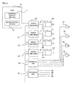
- FIG. 2 shows the configuration of another conventional numerical controller system, in which a plurality of servo amplifiers 20, 21, 22, 23, and a plurality of interface units 50, 51,... are daisy-chained to a numerical controller (CNC) 10 through a serial bus. Also connected to interface units 50, 51,... are sensors S1, S2, S3,..., such as linear scales that sense the positions of servo motor driven tables and other movable parts, sensors that sense temperatures, pressures, voltages, currents, and other quantities, and limit switches.
- CNC numerical controller
- Signals sensed by sensors S1, S2,... are sent to the CNC 10 through interface units 50, 51,....
- the CNC 10 receives the signals from sensors S1, S2,... sequentially, identifies the sensor signals according to their order of reception, and relates the sensors S1, S2,... to the servo motors 30, 31,....
- Sensors S1 to S4 are, for example, linear scales, sensor S1 sensing the position of the movable part driven by servo motor 30, sensor S2 sensing the position of the movable part driven by servo motor 31, sensor S3 sensing the position of the movable part driven by servo motor 32, and sensor S4 sensing the position of the movable part driven by servo motor 33.
- the motor control section 12 uses the signal from sensor S1 for the position loop control of servo motor 30.
- the motor control section 12 uses the signals from sensors S2, S3, S4 for servo motors 31, 32, 33, respectively.
- a plurality of servo motors may be used to drive the table or the other part.
- a single sensor linear scale
- Another need is to share emergency stop signals and other signals from the machine among a plurality of servo amplifiers and servo motors.
- the linear scales or other sensors correspond to the servo motors on a one-to-one basis, preventing the use of signals from a single sensor for the control of a plurality of servo motors.
- the system in FIG. 2 allows the associations between servo motors and sensors to be changed, but does not allow signals from a plurality of sensors to be used by a single servo motor, nor does it permit signals from a single sensor to be used by a plurality of servo motors. Therefore, signals from sensors used by other servo amplifiers cannot be used directly.
- the motor control section 12 has to transfer signals from one servo motor to another, hindering the high-speed control required for servo motors 30 to 33.
- the numerical controller comprises a numerical control section that outputs movement commands and a motor control section that controls motors according to the movement commands from the numerical control section; the numerical controller further comprises interface units that receive signals from sensors and send the received signals to the motor control section, and a data table that stores correspondences between sensors and motors.
- the motor control section receives a signal from the sensor through the interface unit and controls the motor corresponding to the sensor, based on the correspondence of the sensor and motor set in the data table,.
- Sensors may correspond to motors on a one-to-one, one-to-n, or n-to-one basis (n is an integer greater than or equal to two).
- Emergency stop signals can also be placed in correspondence with the motors as sensor signals.
- the present invention provides a numerical controller that can be set so that signals from a plurality of sensors can be used freely for the servo motors controlled by the numerical controller.
- a first embodiment of the present invention will be described below by using the exemplary numerical controller, shown in FIG. 2, to which servo amplifiers and interface units are connected in a daisy chain fashion.
- the numerical controller (CNC) 10 is connected to servo amplifiers 20 to 23 and interface units 50, 51,... in a daisy chain fashion through a serial bus. Signals from the sensors S1 to S4, S5 to S8,... used by the servo motors are collected at respective interface units 50, 51,..., and sent to the CNC 10.
- the CNC 10 receives these sensor signals in a predetermined order.
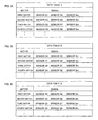
- the CNC 10 in this embodiment has a data table that associates servo motors with the signals from the sensors as shown in FIG. 3A, 3B, or 3C.
- sensors and servo motors are associated as follows: sensor S1 is a linear scale that senses the position of the movable part driven by the first servo motor 30; sensor S2 is a linear scale that senses the position of the movable part driven by the second servo motor 31; sensor S3 is a linear scale that senses the position of the movable part driven by the third servo motor 32; sensor S4 is a linear scale that senses the position of the movable part driven by the fourth servo motor 33.
- the signals from sensors S5, S6, S7, S8 are used for the control of the first, second, third, and fourth servo motors 30, 31, 32, 33, respectively.
- a signal from a sensor Sm (not shown in FIG. 2) can be sent to servo motors 30 to 33 as an emergency stop signal.
- Data table 1 assigns sensors S1, S5, Sm to the first servo motor 30, sensors S2, S6, Sm to the second servo motor 31, sensors S3, S7, Sm to the third servo motor 32, and sensors S4, S8, Sm to the fourth servo motor 33.
- Data table 1 is stored in the numerical control section 11 with these settings.
- the numerical control section 11 transfers the contents of data table 1 to the motor control section 12.
- the motor control section 12 in the CNC 10 then receives the sensor signals sent from sensors S1, S2, S3, S4, S5,... in that order through the daisy-chained serial bus.
- the motor control section 12 identifies the sending sensors according to the order in which the sensor signals are received, and determines the servo motors corresponding to the identified sensors with reference to data table 1.
- the motor control section 12 then controls the servo motors according to the received sensor signals.
- the motor control section 12 performs position loop control on each of the first to fourth servo motors (30 to 33) individually by using the signals from sensors S1, S2, S3, S4, referring to data table 1. If an emergency stop signal is input from the sensor Sm associated with all the servo motors, the motor control section 12 stops the operation of all the servo motors.
- one movable part such as a table is driven by the first and second servo motors and the position of the movable part is sensed by a single linear scale (sensor S1, for example).
- the motor control section 12 associates the first and second servo motors with sensor S1 as shown in data table 2 in FIG. 3B.
- sensor S2 is absent.
- the signal from sensor S6 is used to control the first servo motor 30 and second servo motor 31, and the first servo motor 30 uses the signal from sensor S5 instead of the signal from sensor S1.
- data table 3 in which sensors S5 and S6 are associated with the first servo motor 30 and sensors S2 and S6 with the second servo motor 31, can be set and stored.
- single-sensor signals entering the numerical controller through an interface unit can be shared with a plurality of servo motors according to the settings in the data table.
- a single servo motor can use signals from a plurality of sensors. Any one or more sensors can be associated with any one or more servo motors just by setting arbitrary correspondences between servo motors and sensors in a data table. Therefore, by using a data table, the inventive numerical controller permits easy system alteration and expansion.
- a single motor control section 12 is provided in the CNC 10. However, as many motor control sections 12 as there are servo motors may be installed. Motor control sections 12 can also be installed in servo amplifiers.
- a plurality of sensors are connected to the numerical controller through a serial bus.
- a parallel bus may be used for connecting the plurality of sensors, in which case the sensor signals are read in a predetermined pattern and the corresponding sensors are identified from the order of the sensor signals in the pattern, rather than the order in which the signals are received.
- a servo system In a servo system, all sorts of applications can be handled easily: information from a plurality of sensors can be used for controlling a single servo motor, information from a single sensor can be used for controlling a plurality of servo motors. Since input signals received by the numerical controller can be monitored directly by the processor in the motor control section, input/output control of a grouped plurality of axes can be achieved easily.
Landscapes
- Engineering & Computer Science (AREA)
- Human Computer Interaction (AREA)
- Manufacturing & Machinery (AREA)
- Physics & Mathematics (AREA)
- General Physics & Mathematics (AREA)
- Automation & Control Theory (AREA)
- Numerical Control (AREA)
Abstract
A data table (1, 2 or 3) stored in a numerical controller associates motors controlled by the numerical controller with information from sensors (S1-Sm) used by the motors. When the numerical controller is turned on, the contents of the data table (1, 2 or 3) are sent from the numerical control section to the motor control section. The motor control section controls each motor (e.g. FIRST MOTOR) by using information from the sensors (S1, S5, Sm) associated with the motor in the data table.

Description
- The present invention relates to a numerical controller for controlling a machine tool or the like and, more particularly, to a numerical controller with a novel system configuration of sensors and servo motors that use signals from the sensors.
- FIG. 1 is a block diagram illustrating the main elements of a system in which a numerical controller controls a machine tool or the like in one conventional mode. The numerical controller (CNC) 10 comprises a
numerical control section 11 and amotor control section 12 that controls motors. - Following a machining program or the like, the
numerical control section 11 outputs movement commands for individual motors to amotor control section 12. Themotor control section 12 uses the commands to perform control functions such as position loop control and velocity loop control, generate pulse width modulation (PWM) signals for rotating the individual servo motors, and output the PWM signals toservo amplifiers Servo amplifiers respective servo motors -
Encoders respective servo motors servo motors servo motors motor control section 12 in the CNC throughservo amplifiers - Tables and other movable parts driven by servo
motors CNC 10 throughservo amplifiers motor control section 12 performs feedback control concerning the positions of the movable parts on the basis of the feedback signals from these sensors. The correspondence among sensors S1, S2, S3,...,servo amplifiers motors - FIG. 2 shows the configuration of another conventional numerical controller system, in which a plurality of
servo amplifiers interface units interface units - Signals sensed by sensors S1, S2,... are sent to the
CNC 10 throughinterface units CNC 10 receives the signals from sensors S1, S2,... sequentially, identifies the sensor signals according to their order of reception, and relates the sensors S1, S2,... to theservo motors servo motor 30, sensor S2 sensing the position of the movable part driven byservo motor 31, sensor S3 sensing the position of the movable part driven byservo motor 32, and sensor S4 sensing the position of the movable part driven byservo motor 33. Themotor control section 12 then uses the signal from sensor S1 for the position loop control ofservo motor 30. Likewise, themotor control section 12 uses the signals from sensors S2, S3, S4 forservo motors - When a movable table or another part of a machine tool must move at high speed or the machine tool is large, a large torque is required. In this case, a plurality of servo motors may be used to drive the table or the other part. Although the table or the other part is driven by a plurality of servo motors, a single sensor (linear scale) is attached to it for sensing its position or speed, creating a need to share the signal sensed by the linear scale among the plurality of servo motors. Another need is to share emergency stop signals and other signals from the machine among a plurality of servo amplifiers and servo motors.
- In the system in FIG. 1, however, the linear scales or other sensors correspond to the servo motors on a one-to-one basis, preventing the use of signals from a single sensor for the control of a plurality of servo motors. The system in FIG. 2 allows the associations between servo motors and sensors to be changed, but does not allow signals from a plurality of sensors to be used by a single servo motor, nor does it permit signals from a single sensor to be used by a plurality of servo motors. Therefore, signals from sensors used by other servo amplifiers cannot be used directly.
- To enable the use of signals from other non-assigned sensors in this system, the
motor control section 12 has to transfer signals from one servo motor to another, hindering the high-speed control required forservo motors 30 to 33. - The numerical controller according to the present invention comprises a numerical control section that outputs movement commands and a motor control section that controls motors according to the movement commands from the numerical control section; the numerical controller further comprises interface units that receive signals from sensors and send the received signals to the motor control section, and a data table that stores correspondences between sensors and motors. The motor control section receives a signal from the sensor through the interface unit and controls the motor corresponding to the sensor, based on the correspondence of the sensor and motor set in the data table,.
- Sensors may correspond to motors on a one-to-one, one-to-n, or n-to-one basis (n is an integer greater than or equal to two). Emergency stop signals can also be placed in correspondence with the motors as sensor signals.
- The present invention provides a numerical controller that can be set so that signals from a plurality of sensors can be used freely for the servo motors controlled by the numerical controller.
- The purposes and advantages of the present invention, including those described above, will be clarified by reference to the attached drawings in combination with the description of the embodiment presented below. Of these drawings:
- FIG. 1 is a block diagram indicating the main elements of a conventional control system in which a numerical controller is used for a machine tool or like;
- FIG. 2 is a block diagram indicating the main elements of a control system which may embody either the prior art or the present invention, and in which a numerical controller is used for a machine tool or the like; and
- FIGS. 3A to 3C illustrate exemplary data tables used in the present invention.
- A first embodiment of the present invention will be described below by using the exemplary numerical controller, shown in FIG. 2, to which servo amplifiers and interface units are connected in a daisy chain fashion. The numerical controller (CNC) 10 is connected to
servo amplifiers 20 to 23 andinterface units respective interface units CNC 10. TheCNC 10 receives these sensor signals in a predetermined order. - So far this is similar to the prior art. In the present invention, however, a data table that defines the correspondence between servo motors and sensors is provided so that each servo motor can use signals from arbitrary sensors.
- The
CNC 10 in this embodiment has a data table that associates servo motors with the signals from the sensors as shown in FIG. 3A, 3B, or 3C. - For example, suppose that sensors and servo motors are associated as follows: sensor S1 is a linear scale that senses the position of the movable part driven by the
first servo motor 30; sensor S2 is a linear scale that senses the position of the movable part driven by thesecond servo motor 31; sensor S3 is a linear scale that senses the position of the movable part driven by thethird servo motor 32; sensor S4 is a linear scale that senses the position of the movable part driven by thefourth servo motor 33. The signals from sensors S5, S6, S7, S8 are used for the control of the first, second, third, andfourth servo motors servo motors 30 to 33 as an emergency stop signal. - The correspondence between sensors and servo motors described above is defined in data table 1 shown in FIG. 3A. Data table 1 assigns sensors S1, S5, Sm to the
first servo motor 30, sensors S2, S6, Sm to thesecond servo motor 31, sensors S3, S7, Sm to thethird servo motor 32, and sensors S4, S8, Sm to thefourth servo motor 33. Data table 1 is stored in thenumerical control section 11 with these settings. - When the
CNC 10 storing data table 1 shown in FIG. 3A is turned on and the system is started up, thenumerical control section 11 transfers the contents of data table 1 to themotor control section 12. Themotor control section 12 in theCNC 10 then receives the sensor signals sent from sensors S1, S2, S3, S4, S5,... in that order through the daisy-chained serial bus. Themotor control section 12 identifies the sending sensors according to the order in which the sensor signals are received, and determines the servo motors corresponding to the identified sensors with reference to data table 1. Themotor control section 12 then controls the servo motors according to the received sensor signals. - Assuming that sensors S1, S2, S3, S4 are linear scales that sense the positions of the movable parts driven by the first to
fourth servo motors motor control section 12 performs position loop control on each of the first to fourth servo motors (30 to 33) individually by using the signals from sensors S1, S2, S3, S4, referring to data table 1. If an emergency stop signal is input from the sensor Sm associated with all the servo motors, themotor control section 12 stops the operation of all the servo motors. - In another example, one movable part such as a table is driven by the first and second servo motors and the position of the movable part is sensed by a single linear scale (sensor S1, for example). In this case, to perform position loop control on the first and second servo motors according to the signal from the single linear scale, the
motor control section 12 associates the first and second servo motors with sensor S1 as shown in data table 2 in FIG. 3B. In this example, sensor S2 is absent. - In yet another example, shown in FIG. 3C, the signal from sensor S6 is used to control the
first servo motor 30 andsecond servo motor 31, and thefirst servo motor 30 uses the signal from sensor S5 instead of the signal from sensor S1. Then data table 3, in which sensors S5 and S6 are associated with thefirst servo motor 30 and sensors S2 and S6 with thesecond servo motor 31, can be set and stored. - As described above, single-sensor signals entering the numerical controller through an interface unit can be shared with a plurality of servo motors according to the settings in the data table. Conversely, a single servo motor can use signals from a plurality of sensors. Any one or more sensors can be associated with any one or more servo motors just by setting arbitrary correspondences between servo motors and sensors in a data table. Therefore, by using a data table, the inventive numerical controller permits easy system alteration and expansion.
- In the embodiment in FIG. 2, a single
motor control section 12 is provided in theCNC 10. However, as manymotor control sections 12 as there are servo motors may be installed.Motor control sections 12 can also be installed in servo amplifiers. - In the embodiment described above, a plurality of sensors are connected to the numerical controller through a serial bus. However, a parallel bus may be used for connecting the plurality of sensors, in which case the sensor signals are read in a predetermined pattern and the corresponding sensors are identified from the order of the sensor signals in the pattern, rather than the order in which the signals are received.
- In a servo system, all sorts of applications can be handled easily: information from a plurality of sensors can be used for controlling a single servo motor, information from a single sensor can be used for controlling a plurality of servo motors. Since input signals received by the numerical controller can be monitored directly by the processor in the motor control section, input/output control of a grouped plurality of axes can be achieved easily.
Claims (5)
- A numerical controller having a numerical control section that outputs movement commands and a motor control section that controls motors according to the movement commands from the numerical control section, the numerical controller comprising:an interface unit for receiving signals from sensors and sending the received signals to the motor control section; anda data table storing a correspondence between the sensors and the motors;wherein the motor control section receives the signals from the sensors through the interface unit and controls the motors corresponding to the sensors according to the correspondence between the sensors and the motors set in the data table.
- The numerical controller of claim 1, wherein the correspondence between the sensors and the motors is one-to-one, one-to-n, or n-to-one (n being an integer greater than or equal to two).
- The numerical controller of claim 1 or 2, wherein an emergency stop signal is associated with the motors as one of the sensor signals.
- A numerical controller in which a plurality of servo amplifiers and one interface unit or a plurality of interface units are interconnected through a serial bus in a daisy chain fashion, the numerical controller comprising:a plurality of servo motors controlled by the plurality of servo amplifiers;a plurality of sensors, including a sensor that senses the position of a movable part driven by at least one of the servo motors; anda memory storing a data table in which one or more of the sensors in the plurality of sensors are assigned to each of the plurality of servo motors; wherein:the interface unit receives a plurality of signals from the sensors and sends the plurality of signals to the numerical controller; andthe numerical controller receives the signals sent from the plurality of sensors through the interface unit sequentially, identifies a sensor that has sent each of the signals according to an order of reception of the signals, determines a servo motor corresponding to the identified sensor with reference to the data table, and controls the determined servo motor according to the signal received from the sensor.
- The numerical controller of claim 4, wherein the sensors include at least one of a linear scale that senses the position of a table driven by a servo motor, a sensor that senses a temperature, a pressure, a voltage, or a current, and a limit switch.
Applications Claiming Priority (2)
| Application Number | Priority Date | Filing Date | Title |
|---|---|---|---|
| JP2003071500A JP2004280506A (en) | 2003-03-17 | 2003-03-17 | Numerical control device |
| JP2003071500 | 2003-03-17 |
Publications (1)
| Publication Number | Publication Date |
|---|---|
| EP1460503A1 true EP1460503A1 (en) | 2004-09-22 |
Family
ID=32821277
Family Applications (1)
| Application Number | Title | Priority Date | Filing Date |
|---|---|---|---|
| EP04251380A Withdrawn EP1460503A1 (en) | 2003-03-17 | 2004-03-10 | Numerical controller |
Country Status (4)
| Country | Link |
|---|---|
| US (1) | US7026778B2 (en) |
| EP (1) | EP1460503A1 (en) |
| JP (1) | JP2004280506A (en) |
| CN (1) | CN1306349C (en) |
Cited By (3)
| Publication number | Priority date | Publication date | Assignee | Title |
|---|---|---|---|---|
| EP1793293A1 (en) * | 2005-11-30 | 2007-06-06 | Fanuc Ltd | Numerical control system with two separated daisy-chain bus systems for the connection to servo amplifiers and position encoders |
| CN110495091A (en) * | 2017-03-30 | 2019-11-22 | 株式会社安川电机 | Motor control system, control method, and motor control device |
| EP3605828A4 (en) * | 2017-03-31 | 2020-11-11 | Kabushiki Kaisha Yaskawa Denki | ENGINE CONTROL DEVICE, ENGINE CONTROL METHOD AND ENGINE CONTROL SYSTEM |
Families Citing this family (15)
| Publication number | Priority date | Publication date | Assignee | Title |
|---|---|---|---|---|
| JP3841762B2 (en) * | 2003-02-18 | 2006-11-01 | ファナック株式会社 | Servo motor control system |
| JP2006107284A (en) * | 2004-10-07 | 2006-04-20 | Fanuc Ltd | Numeric control system |
| US7463003B2 (en) * | 2006-08-10 | 2008-12-09 | Sodick Co., Ltd. | Motor control system for controlling a plurality of motors |
| US7602132B2 (en) * | 2006-09-27 | 2009-10-13 | Rockwell Automation Technologies, Inc. | Methods and system for motor drive information capture |
| JP4182132B2 (en) * | 2007-03-27 | 2008-11-19 | ファナック株式会社 | Motor control system |
| US9598897B2 (en) * | 2007-06-21 | 2017-03-21 | Tait Towers Manufacturing, LLC | Portable curtain retraction device and system |
| JP2009217627A (en) * | 2008-03-11 | 2009-09-24 | Fanuc Ltd | Numerical controller having function to switch between pressure control and position control |
| JP2011217530A (en) * | 2010-03-31 | 2011-10-27 | Toshiba Mach Co Ltd | Servo control method and servo control apparatus |
| CN103563238B (en) * | 2011-06-03 | 2016-03-23 | 株式会社安川电机 | Multiaxis electric motor drive system and multiaxis motor drive |
| JP5822621B2 (en) * | 2011-09-27 | 2015-11-24 | 富士機械製造株式会社 | Servo drive system |
| DE102012200239A1 (en) * | 2012-01-10 | 2013-07-11 | Robert Bosch Gmbh | sensor arrangement |
| JP5800886B2 (en) * | 2013-12-16 | 2015-10-28 | ファナック株式会社 | A numerical controller that gives commands to multiple axes with a single command |
| JP6552314B2 (en) * | 2015-07-24 | 2019-07-31 | 日本電産サンキョー株式会社 | Motor controller |
| CN113228618A (en) * | 2020-07-31 | 2021-08-06 | 深圳市大疆创新科技有限公司 | Motor control method, device and system and computer readable storage medium |
| FR3132776B1 (en) * | 2022-02-16 | 2024-01-26 | Micro Controle Spectra Physics | SYSTEM AND METHOD FOR IMPLEMENTING POSITION SYNCHRONIZED OUTPUT (PSO) CONTROL TECHNIQUES |
Citations (2)
| Publication number | Priority date | Publication date | Assignee | Title |
|---|---|---|---|---|
| EP0597561A1 (en) * | 1992-11-13 | 1994-05-18 | MANNESMANN Aktiengesellschaft | Transfer system for data exchange |
| EP1022630A1 (en) * | 1999-01-23 | 2000-07-26 | ABB Research Ltd. | Method for the engineering of a manufacturing line |
Family Cites Families (10)
| Publication number | Priority date | Publication date | Assignee | Title |
|---|---|---|---|---|
| US4513379A (en) * | 1982-09-07 | 1985-04-23 | General Electric Company | Customization window for a computer numerical control system |
| US4632612A (en) * | 1985-08-26 | 1986-12-30 | Kearney & Trecker Corporation | Spindle orientation apparatus |
| JPS6417102A (en) | 1987-07-11 | 1989-01-20 | Agency Ind Science Techn | Multi-freedom degree manipulator |
| JPH0833763B2 (en) * | 1988-03-01 | 1996-03-29 | 義昭 垣野 | Numerical control unit |
| JPH03260708A (en) * | 1990-03-09 | 1991-11-20 | Toshiba Mach Co Ltd | Position error correcting method |
| JPH07200027A (en) | 1993-12-29 | 1995-08-04 | Canon Inc | Control device for automatic assembly equipment |
| JP3615596B2 (en) * | 1995-08-22 | 2005-02-02 | ファナック株式会社 | Numerical controller |
| JPH10254524A (en) * | 1997-03-10 | 1998-09-25 | Fanuc Ltd | Inter-unit communication method in controller of machine |
| KR100245988B1 (en) * | 1997-06-27 | 2000-03-02 | 서평원 | Data stream controlling apparatus for constituting daisy-chain of base station |
| CN1219374C (en) * | 2001-04-02 | 2005-09-14 | 中兴通讯股份有限公司 | Device for realising channel share |
-
2003
- 2003-03-17 JP JP2003071500A patent/JP2004280506A/en active Pending
-
2004
- 2004-03-10 US US10/796,277 patent/US7026778B2/en not_active Expired - Lifetime
- 2004-03-10 EP EP04251380A patent/EP1460503A1/en not_active Withdrawn
- 2004-03-16 CN CNB2004100086687A patent/CN1306349C/en not_active Expired - Fee Related
Patent Citations (2)
| Publication number | Priority date | Publication date | Assignee | Title |
|---|---|---|---|---|
| EP0597561A1 (en) * | 1992-11-13 | 1994-05-18 | MANNESMANN Aktiengesellschaft | Transfer system for data exchange |
| EP1022630A1 (en) * | 1999-01-23 | 2000-07-26 | ABB Research Ltd. | Method for the engineering of a manufacturing line |
Non-Patent Citations (2)
| Title |
|---|
| DUGERN O V ET AL: "EINE MODULARE GRUNDSTEUERUNG FUR FLEXIBLE MONTAGEZELLEN", AUTOMATISIERUNGSTECHNISCHE PRAXIS - ATP, OLDENBOURG VERLAG. MUNCHEN, DE, vol. 32, no. 1, 1990, pages 22 - 29, XP000126014, ISSN: 0178-2320 * |
| KENNEL R ET AL: "DATENKOMMUNIKATION UEBER DAS BUSSYSTEM SERCOS INTERFACE", AUTOMATISIERUNGSTECHNISCHE PRAXIS - ATP, OLDENBOURG VERLAG. MUNCHEN, DE, vol. 33, no. 7, 1 July 1991 (1991-07-01), pages 363 - 368, XP000243095, ISSN: 0178-2320 * |
Cited By (7)
| Publication number | Priority date | Publication date | Assignee | Title |
|---|---|---|---|---|
| EP1793293A1 (en) * | 2005-11-30 | 2007-06-06 | Fanuc Ltd | Numerical control system with two separated daisy-chain bus systems for the connection to servo amplifiers and position encoders |
| CN110495091A (en) * | 2017-03-30 | 2019-11-22 | 株式会社安川电机 | Motor control system, control method, and motor control device |
| EP3605827A4 (en) * | 2017-03-30 | 2020-11-25 | Kabushiki Kaisha Yaskawa Denki | ENGINE CONTROL SYSTEM, CONTROL METHOD AND ENGINE CONTROL DEVICE |
| US11181881B2 (en) | 2017-03-30 | 2021-11-23 | Kabushiki Kaisha Yaskawa Denki | Motor control system, control method, and motor control apparatus |
| CN110495091B (en) * | 2017-03-30 | 2023-01-20 | 株式会社安川电机 | Motor control system, control method, and motor control device |
| EP3605828A4 (en) * | 2017-03-31 | 2020-11-11 | Kabushiki Kaisha Yaskawa Denki | ENGINE CONTROL DEVICE, ENGINE CONTROL METHOD AND ENGINE CONTROL SYSTEM |
| US11316461B2 (en) | 2017-03-31 | 2022-04-26 | Kabushiki Kaisha Yaskawa Denki | Motor control apparatus, motor control method, and motor control system |
Also Published As
| Publication number | Publication date |
|---|---|
| CN1306349C (en) | 2007-03-21 |
| JP2004280506A (en) | 2004-10-07 |
| US20040207357A1 (en) | 2004-10-21 |
| CN1530784A (en) | 2004-09-22 |
| US7026778B2 (en) | 2006-04-11 |
Similar Documents
| Publication | Publication Date | Title |
|---|---|---|
| US7026778B2 (en) | Numerical controller | |
| JPWO2009057545A1 (en) | Multi-axis drive driver control method, multi-axis drive driver, and multi-axis drive control system including the same | |
| US20050174086A1 (en) | Machine controller | |
| JPH04232509A (en) | Controlling method for machine tool or robot | |
| EP0965895A2 (en) | Control System with an input/output card interface | |
| US4963803A (en) | Numerically controlled machine tool | |
| WO1986006319A1 (en) | System for switching and controlling unit amount of torque limit value of servo motor for injection molding machine | |
| KR880002076A (en) | Numerical Control Device | |
| JPH10268924A (en) | Servo system | |
| JP4683325B2 (en) | Multi-axis motor control system | |
| JP2003044144A (en) | Multi-axis synchronous control device, multi-axis synchronous control method, and multi-axis synchronous control program | |
| WO1986003905A1 (en) | Drive control apparatus for servo motors | |
| KR0136694B1 (en) | Drive system of ac servo motor | |
| JPS63165907A (en) | Digital servo numerical controller | |
| JPS6354605A (en) | Numerical controller | |
| KR940006959B1 (en) | Output Limit Circuit of Controller | |
| Abbas et al. | Versatile controller for multi-stepper motor operation | |
| KR0161001B1 (en) | Driving control device of robot system | |
| JPH0546225A (en) | Robot controller | |
| JP2868492B2 (en) | Numerical control unit | |
| JPH0553620A (en) | Production/processing control system | |
| JPH06138916A (en) | Data transfer system for i/o module | |
| KR200388510Y1 (en) | Control device of plurality of servo motors using time-division pulses | |
| EP3605828B1 (en) | Motor control system and motor control method | |
| JPH0343864B2 (en) |
Legal Events
| Date | Code | Title | Description |
|---|---|---|---|
| PUAI | Public reference made under article 153(3) epc to a published international application that has entered the european phase |
Free format text: ORIGINAL CODE: 0009012 |
|
| AK | Designated contracting states |
Kind code of ref document: A1 Designated state(s): AT BE BG CH CY CZ DE DK EE ES FI FR GB GR HU IE IT LI LU MC NL PL PT RO SE SI SK TR |
|
| AX | Request for extension of the european patent |
Extension state: AL HR LT LV MK |
|
| 17P | Request for examination filed |
Effective date: 20041122 |
|
| AKX | Designation fees paid |
Designated state(s): DE |
|
| 17Q | First examination report despatched |
Effective date: 20060123 |
|
| STAA | Information on the status of an ep patent application or granted ep patent |
Free format text: STATUS: THE APPLICATION IS DEEMED TO BE WITHDRAWN |
|
| 18D | Application deemed to be withdrawn |
Effective date: 20080624 |