EP1460465A1 - Farbfilterradeinheit und Farbfilterrad - Google Patents
Farbfilterradeinheit und Farbfilterrad Download PDFInfo
- Publication number
- EP1460465A1 EP1460465A1 EP03019761A EP03019761A EP1460465A1 EP 1460465 A1 EP1460465 A1 EP 1460465A1 EP 03019761 A EP03019761 A EP 03019761A EP 03019761 A EP03019761 A EP 03019761A EP 1460465 A1 EP1460465 A1 EP 1460465A1
- Authority
- EP
- European Patent Office
- Prior art keywords
- fixing element
- color wheel
- motor
- holder
- housing
- Prior art date
- Legal status (The legal status is an assumption and is not a legal conclusion. Google has not performed a legal analysis and makes no representation as to the accuracy of the status listed.)
- Ceased
Links
Images


Classifications
-
- G—PHYSICS
- G02—OPTICS
- G02B—OPTICAL ELEMENTS, SYSTEMS OR APPARATUS
- G02B26/00—Optical devices or arrangements for the control of light using movable or deformable optical elements
- G02B26/007—Optical devices or arrangements for the control of light using movable or deformable optical elements the movable or deformable optical element controlling the colour, i.e. a spectral characteristic, of the light
- G02B26/008—Optical devices or arrangements for the control of light using movable or deformable optical elements the movable or deformable optical element controlling the colour, i.e. a spectral characteristic, of the light in the form of devices for effecting sequential colour changes, e.g. colour wheels
Definitions
- the invention relates to a color wheel assembly and a color wheel thereof, and, more particularly, to a color wheel assembly and a color wheel thereof, which are used in projection technology.
- image projection systems have become popular items in the optoelectronic industry owing to multiple requirements of a system having large display area, small dimension, and thin, light composition.
- the popular projection systems are divided into three types including a liquid crystal display (LCD) type, a liquid crystal on silicon (LCoS) type, and a digital light processing (DLP) type, wherein the single-panel LCoS and DLP types advantageously have simplified systems and the following description will take the DLP type as an example.
- LCD liquid crystal display
- LCDoS liquid crystal on silicon
- DLP digital light processing
- a digital control method and a reflection principle are adopted.
- SCR Sequential Color Recapture
- light rays are integrated or converged by a light integration rod and then pass through the color filter of the color wheel for splitting the light rays.
- the split light rays are then projected onto a digital micro-mirror device (DMD).
- DMD digital micro-mirror device
- the DMD is used to replace the liquid crystal panel for representing images in the conventional liquid crystal projector. Since the DMD includes several movable micro-mirrors, driving electrodes may control the tilt angle and deflection time of each movable mirror. Then, the light rays may be projected to form an image by switching the reflection directions of the light rays.
- each optical device In the DLP projector, different clamping mechanisms are used to fix the color wheel and the light integration rod in the DLP projector, so that the relative position between the color wheel and the light integration rod may be controlled.
- the position of each optical device, through which light rays pass relates to the overall imaging quality of the DLP projector. Accordingly, each optical device has to be precisely positioned. Furthermore, when the color wheel is a SCR color wheel, the alignment precision between the color wheel and the light integration rod is more highly required.
- the relative position between the color wheel and the light integration rod has to be adjusted.
- the relative positions between other optical devices, the color wheel and the light integration rod also have to be considered. Consequently, it is necessary to spend longer time to artificially adjust the relative position between the color wheel and the light integration rod as well as that between other optical devices, the color wheel and light integration rod. Meanwhile, the precision of correctly adjusting the relative position between the color wheel and the light integration rod also cannot be easily controlled, and the reproducibility is also poor.
- an objective of the invention is to provide a color wheel assembly and a color wheel thereof capable of solving the orientating problems between a color wheel and an optical element.
- the invention provides a color wheel assembly including a color filter, a motor, a fixing element, and an optical element.
- the motor has a housing and a motor body, and the housing is set to a side of a central axis of the motor body.
- the color filter is set on the housing of the motor.
- the motor body is fixed on the fixing element.
- the fixing element has an outwardly extending holder.
- the optical element is jointed with the holder.
- the invention also provides a color wheel assembly including a color filter, a motor, a fixing element, an auxiliary fixing element, and an optical element.
- the motor has a housing and a motor body, and the housing is set to a side of a central axis of the motor body.
- the color filter is set on the housing of the motor.
- the motor body is fixed on the fixing element.
- the auxiliary fixing element is set on the fixing element and has an outwardly extending holder.
- the optical element is jointed with the holder.
- the invention also provides a color wheel including a color filter, a motor, and a fixing element.
- the motor has a housing and a motor body, and the housing is set to a side of a central axis of the motor body.
- the color filter is set on the housing of the motor.
- the motor body is fixed on the fixing element.
- the fixing element has an outwardly extending holder.
- the invention also provides a color wheel including a color filter, a motor, a fixing element, and an auxiliary fixing element.
- the motor has a housing and a motor body, and the housing is set to a side of a central axis of the motor body.
- the color filter is set on the housing of the motor.
- the motor body is fixed on the fixing element.
- the auxiliary fixing element is set on the fixing element and has an outwardly extending holder.
- the color wheel assembly and the color wheel thereof in this invention have the outwardly extending holder to joint the color wheel with the optical element.
- the relative position between the color wheel and the optical element in this invention needs not to be adjusted using different clamping mechanisms. Instead, the relative position between the color wheel and the optical element is fixed by using the holder of the fixing element or the auxiliary fixing element, and only the relative position between the color wheel and other optical devices of the projector needs to be adjusted. Consequently, the invention is laborsaving and timesaving in adjustment. Meanwhile, since no unnecessary clamping mechanism is needed, the dimension of the projector may be reduced, and the manufacturing cost may be further decreased. In addition, the alignment precision and reproducibility are also improved, and the overall quality of the projector is also improved.
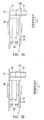
- FIGS. 1A, 1B and 1C are schematic side views showing a color wheel assembly according to a first embodiment of the invention.
- FIG. 2A is a cross-sectional view showing the holder taken along a line A-A of FIG. 1A.
- FIGS. 2B and 2C are cross-sectional views showing the holder taken along a line B-B of FIG. 1C.
- FIGS. 3A and 3B are schematic side views showing a color wheel assembly according to a second embodiment of the invention.
- FIGS. 4A and 4B are schematic side views showing a color wheel according to a third embodiment of the invention.
- FIGS. 5A and 5B are schematic side views showing a color wheel according to a fourth embodiment of the invention.
- a color wheel assembly 1 includes a color filter 11, a motor 12, a fixing element 13, and an optical element 14.
- the motor 12 has a housing 121 and a motor body 122, and the housing 121 is set to a side of a central axis of the motor body 122.
- the color filter 11 is set on the housing 121 of the motor 12.
- the motor body 122 is fixed to the fixing element 13.
- the fixing element 13 has an outwardly extending holder 131.
- the optical element 14 is jointed with the holder 131.
- the color filter 11 may be a circular filter or a ring-shaped filter composed of at least a red section, at least a green section, and at least a blue section.
- the color filter 11 also may be a circular filter or a ring-shaped filter composed of at least a red section, at least a green section, at least a blue section, and at least a transparent section.
- the color filter 11 also may be a ring-shaped transparent plate or a circular transparent plate, on which at least a red film, at least a green film, and at least a blue film are formed.
- the motor 12 is composed of the housing 121 and the motor body 122, and the housing 121 is set to a side of a central axis of the motor body 122.
- the color filter 11 is set on the housing 121 of the motor 12.
- the color filter 11 is set on the housing 121 by way of, for example, a fitting, adhering process or placing the color filter 11 over the housing 121.
- the motor body 122 is mainly composed of a shell, a magnetic ring (not shown), laminated steel stack (not shown) and a coil (not shown).
- the laminated steel stack produces a magnetic force and a magnetic field. Controlling the positive/negative property and the intensity of the flowing current may change the magnetic field in sequence, or produce a rotating magnetic field, to interact with the magnetic ring and thus cause the magnetic ring to rotate.
- the motor body 122 is fixed on the fixing element 13, and the fixing element 13 has the outwardly extending holder 131.
- the fixing element 13 is a fixing plate for fixing the color wheel assembly 1 in a projector (not shown).
- the fixing element 13 and the holder 131 are integrally formed, as shown in FIGS. 1A and 1C.
- the fixing element 13 is connected to or jointed with the holder 131, as shown in FIG. 1B.
- the fixing element 13 may be connected to or jointed with the holder 131 by way of adhering, riveting or screwing.
- the holder 131 is jointed with the optical element 14.
- the optical element 14 is used to guide light rays or change the traveling directions of light rays, for example, and to converge light rays.
- the optical element 14 may also homogenize the brightness distribution of light rays and control the length-to-width ratio of the projected image.
- the optical element 14 is a light integration rod, which is generally called as a rod, a light tunnel, a light pipe, etc. in the field of the art.
- the optical element 14 also may be a lens or lenses.
- the holder 131 may be jointed with the optical element 14 by way of adhering, riveting, or screwing.
- an adhesive may be used to adhere the optical element 14 to the holder 131, wherein the adhesive may be a light-cured adhesive or a heat-cured adhesive.
- the adhesive may be a light-cured adhesive or a heat-cured adhesive.
- connection portion between the holder 131 and the optical element 14 has a shape matching with the external shape of the optical element 14.
- the cross section of the holder 131 taken along a line A-A of FIG. 1A may be of an "L" shape (FIG. 2A).
- the cross section of the holder 131 taken along a line B-B of FIG. 1C may be of a " ⁇ " shape (FIG. 2B) and a rectangular ring shape (FIG. 2C), or the like.
- the color wheel assembly 1 in this embodiment further includes a cap 15 set on the color filter 11 by way of embedding or adhering.
- the cap 15 is used to enlarge the adhesion area between the color filter 11 and the housing 121.
- a color wheel assembly 2 includes a color filter 21, a motor 22, a fixing element 23, an auxiliary fixing element 24, and an optical element 25.
- the motor 22 is composed of a housing 221 and a motor body 222, wherein the housing 221 is set to a side of a central axis of the motor body 222.
- the color filter 21 is set on the housing 221 of the motor 22, and the motor body 222 is fixed on the fixing element 23.
- the auxiliary fixing element 24 is set on the fixing element 23 and has an outwardly extending holder 241.
- the optical element 25 is jointed with the holder 241.
- the color wheel assembly 2 in this embodiment further includes a cap 26 set on the color filter 21.
- the motor body 222 is fixed to the fixing element 23.
- the fixing element 23 is a fixing plate for fixing the color wheel assembly 2 in a projector (not shown).
- the auxiliary fixing element 24 is set on the fixing element 23 and has the outwardly extending holder 241. In this embodiment, the alignment of the auxiliary fixing element 24 and the fixing element 23 are aligned under a microscope. Then, the auxiliary fixing element 24 is fixed to the fixing element 23 by way of adhering followed by solder bonding. Of course, the auxiliary fixing element 24 also may be fixed to the fixing element 23 by way of adhering, riveting, screwing or solder bonding.
- the auxiliary fixing element 24 and the holder 241 are integrally formed, as shown in FIG. 3A.
- the auxiliary fixing element 24 is fixed to the holder 241, as shown in FIG. 3B.
- the auxiliary fixing element 24 may be fixed to the holder 241 by way of adhering, riveting, or screwing.
- the way of jointing the holder 241 with the optical element 25 and the shape of the holder 241 in the second embodiment are the same as those in the first embodiment.
- the invention utilizes the fixing element of the color wheel assembly to fix and position the color wheel and the optical element in the projector, the relative position between the color wheel and other optical devices of the projector has to be adjusted, but the relative position between the color wheel and the optical element needs not to be adjusted.
- a color wheel 3 includes a color filter 31, a motor 32, and a fixing element 33.
- the motor 32 has a housing 321 and a motor body 322, and the housing 321 is set to a side of a central axis of the motor body 322.
- the color filter 31 is set on the housing 321 of the motor 32.
- the motor body 322 is fixed to the fixing element 33.
- the fixing element 33 has an outwardly extending holder 331.
- the color wheel 3 in this embodiment further includes a cap 34 set on the color filter 31.
- the color filter 31, the motor 32, the housing 321, the motor body 322, the fixing element 33, the holder 331, and the cap 34 have the same features and functions as those in the first embodiment, and detailed descriptions thereof will be omitted.
- a color wheel 4 includes a color filter 41, a motor 42, a fixing element 43, and an auxiliary fixing element 44.
- the motor 42 is composed of a housing 421 and a motor body 422, wherein the housing 421 is set to a side of a central axis of the motor body 422.
- the color filter 41 is set on the housing 421 of the motor 42, and the motor body 422 is fixed on the fixing element 43.
- the auxiliary fixing element 44 is set on the fixing element 43 and has an outwardly extending holder 441.
- the color wheel 4 in this embodiment further includes a cap 45 set on the color filter 41.
- the color filter 41, the motor 42, the housing 421, the motor body 422, the fixing element 43, the auxiliary fixing element 44, and the holder 441 have the same features and functions as those in the second embodiment, and detailed descriptions thereof will be omitted.
- the color wheel assembly and the color wheel thereof in this invention have the outwardly extending holder to joint the color wheel with the optical element.
- the relative position between the color wheel and the optical element in this invention needs not to be adjusted using different clamping mechanisms. Instead, the relative position between the color wheel and the optical element is fixed by using the holder of the fixing element or the auxiliary fixing element, and only the relative position between the color wheel and other optical devices of the projector needs to be adjusted. Consequently, the invention is laborsaving and timesaving in adjustment. Meanwhile, since no unnecessary clamping mechanism is needed, the dimension of the projector may be reduced, and the manufacturing cost may be further decreased. In addition, the alignment precision and reproducibility are also improved, and the overall quality of the projector is also improved.
Landscapes
- Physics & Mathematics (AREA)
- Astronomy & Astrophysics (AREA)
- Spectroscopy & Molecular Physics (AREA)
- General Physics & Mathematics (AREA)
- Optics & Photonics (AREA)
- Projection Apparatus (AREA)
- Mechanical Light Control Or Optical Switches (AREA)
Applications Claiming Priority (4)
| Application Number | Priority Date | Filing Date | Title |
|---|---|---|---|
| CNU03242213XU CN2603415Y (zh) | 2003-03-19 | 2003-03-19 | 色轮 |
| CNU032422121U CN2603414Y (zh) | 2003-03-19 | 2003-03-19 | 色轮组 |
| CN03242213U | 2003-03-19 | ||
| CN03242212U | 2003-03-19 |
Publications (1)
| Publication Number | Publication Date |
|---|---|
| EP1460465A1 true EP1460465A1 (de) | 2004-09-22 |
Family
ID=32825910
Family Applications (1)
| Application Number | Title | Priority Date | Filing Date |
|---|---|---|---|
| EP03019761A Ceased EP1460465A1 (de) | 2003-03-19 | 2003-08-29 | Farbfilterradeinheit und Farbfilterrad |
Country Status (1)
| Country | Link |
|---|---|
| EP (1) | EP1460465A1 (de) |
Cited By (1)
| Publication number | Priority date | Publication date | Assignee | Title |
|---|---|---|---|---|
| JP2016151656A (ja) * | 2015-02-17 | 2016-08-22 | セイコーエプソン株式会社 | 光源装置およびプロジェクター |
Citations (6)
| Publication number | Priority date | Publication date | Assignee | Title |
|---|---|---|---|---|
| DE19708949A1 (de) * | 1996-04-30 | 1997-11-13 | Balzers Hochvakuum | Farbrad und Bilderzeugungsvorrichtung mit einem Farbrad |
| DE19702754A1 (de) * | 1997-01-27 | 1998-07-30 | Zeiss Carl Jena Gmbh | Filterwechsler für Mikroskope |
| US20020003704A1 (en) * | 2000-05-25 | 2002-01-10 | Hideki Ohmae | Color wheel assembly and color sequential display device using the same, color wheel unit and color sequential display device using the same, and color sequential display device |
| US20020105729A1 (en) * | 2001-02-06 | 2002-08-08 | Reflectivity, Inc., A California Corporation | Projection display with full color saturation and variable luminosity |
| US20020135862A1 (en) * | 2000-12-29 | 2002-09-26 | Dewald D. Scott | Illumination system for scrolling color recycling |
| US6474818B1 (en) * | 2000-07-28 | 2002-11-05 | Infocus Corporation | Mirror and aperture based color phase detector for use in a multimedia projection system |
-
2003
- 2003-08-29 EP EP03019761A patent/EP1460465A1/de not_active Ceased
Patent Citations (6)
| Publication number | Priority date | Publication date | Assignee | Title |
|---|---|---|---|---|
| DE19708949A1 (de) * | 1996-04-30 | 1997-11-13 | Balzers Hochvakuum | Farbrad und Bilderzeugungsvorrichtung mit einem Farbrad |
| DE19702754A1 (de) * | 1997-01-27 | 1998-07-30 | Zeiss Carl Jena Gmbh | Filterwechsler für Mikroskope |
| US20020003704A1 (en) * | 2000-05-25 | 2002-01-10 | Hideki Ohmae | Color wheel assembly and color sequential display device using the same, color wheel unit and color sequential display device using the same, and color sequential display device |
| US6474818B1 (en) * | 2000-07-28 | 2002-11-05 | Infocus Corporation | Mirror and aperture based color phase detector for use in a multimedia projection system |
| US20020135862A1 (en) * | 2000-12-29 | 2002-09-26 | Dewald D. Scott | Illumination system for scrolling color recycling |
| US20020105729A1 (en) * | 2001-02-06 | 2002-08-08 | Reflectivity, Inc., A California Corporation | Projection display with full color saturation and variable luminosity |
Cited By (1)
| Publication number | Priority date | Publication date | Assignee | Title |
|---|---|---|---|---|
| JP2016151656A (ja) * | 2015-02-17 | 2016-08-22 | セイコーエプソン株式会社 | 光源装置およびプロジェクター |
Similar Documents
| Publication | Publication Date | Title |
|---|---|---|
| US6419365B1 (en) | Asymmetrical tunnel for spatially integrating light | |
| US20070132961A1 (en) | Projection type display apparatus having micro mirror type display element | |
| US9835936B2 (en) | Angle adjustment apparatus and projection display apparatus | |
| US20210389649A1 (en) | Projection lens and projection apparatus | |
| US8545027B2 (en) | Light control apparatus and projector | |
| US20210373299A1 (en) | Projection lens and projection apparatus | |
| US6705733B1 (en) | Color wheel and washer thereof | |
| US6769776B1 (en) | Color wheel assembly | |
| US6867934B2 (en) | Color wheel | |
| CN100498505C (zh) | 棱镜结构体和投影机 | |
| EP1460465A1 (de) | Farbfilterradeinheit und Farbfilterrad | |
| US7204613B2 (en) | Projection display device | |
| US6769775B2 (en) | Motor of color wheel | |
| US7623308B2 (en) | Rear projection lens device and magnification adjusting method thereof | |
| US20090225281A1 (en) | Projection display system and prism set and manufacturing method thereof | |
| JP2008102536A (ja) | 背面投写型表示装置 | |
| WO2006044096A2 (en) | Split optic support structure and optical system using split optic support structure | |
| US7210821B2 (en) | Light-splitting device | |
| US20040075819A1 (en) | Color wheel and a motor for the same | |
| JP2009198539A (ja) | プロジェクタ、及び調整方法 | |
| JP2007163654A (ja) | プロジェクタ | |
| US11747588B2 (en) | Flexure device | |
| JP2002207251A (ja) | 光変調装置の位置調整装置、光変調装置の位置調整方法、および初期位置調整治具 | |
| US7216990B2 (en) | Integrated lamp and aperture alignment method and system | |
| US20060082739A1 (en) | Panel locating method of a projecting system |
Legal Events
| Date | Code | Title | Description |
|---|---|---|---|
| PUAI | Public reference made under article 153(3) epc to a published international application that has entered the european phase |
Free format text: ORIGINAL CODE: 0009012 |
|
| AK | Designated contracting states |
Kind code of ref document: A1 Designated state(s): AT BE BG CH CY CZ DE DK EE ES FI FR GB GR HU IE IT LI LU MC NL PT RO SE SI SK TR |
|
| AX | Request for extension of the european patent |
Extension state: AL LT LV MK |
|
| 17P | Request for examination filed |
Effective date: 20041208 |
|
| 17Q | First examination report despatched |
Effective date: 20050125 |
|
| AKX | Designation fees paid |
Designated state(s): DE FR GB |
|
| STAA | Information on the status of an ep patent application or granted ep patent |
Free format text: STATUS: THE APPLICATION HAS BEEN REFUSED |
|
| 18R | Application refused |
Effective date: 20071108 |