EP1460311A1 - Sicherheitsmutter und Aufnahmeteil für eine Sicherheitsmutter für einen Linearantrieb - Google Patents
Sicherheitsmutter und Aufnahmeteil für eine Sicherheitsmutter für einen Linearantrieb Download PDFInfo
- Publication number
- EP1460311A1 EP1460311A1 EP04005859A EP04005859A EP1460311A1 EP 1460311 A1 EP1460311 A1 EP 1460311A1 EP 04005859 A EP04005859 A EP 04005859A EP 04005859 A EP04005859 A EP 04005859A EP 1460311 A1 EP1460311 A1 EP 1460311A1
- Authority
- EP
- European Patent Office
- Prior art keywords
- nut
- safety nut
- receiving part
- safety
- contact surface
- Prior art date
- Legal status (The legal status is an assumption and is not a legal conclusion. Google has not performed a legal analysis and makes no representation as to the accuracy of the status listed.)
- Granted
Links
Images


Classifications
-
- F—MECHANICAL ENGINEERING; LIGHTING; HEATING; WEAPONS; BLASTING
- F16—ENGINEERING ELEMENTS AND UNITS; GENERAL MEASURES FOR PRODUCING AND MAINTAINING EFFECTIVE FUNCTIONING OF MACHINES OR INSTALLATIONS; THERMAL INSULATION IN GENERAL
- F16H—GEARING
- F16H25/00—Gearings comprising primarily only cams, cam-followers and screw-and-nut mechanisms
- F16H25/18—Gearings comprising primarily only cams, cam-followers and screw-and-nut mechanisms for conveying or interconverting oscillating or reciprocating motions
- F16H25/20—Screw mechanisms
- F16H25/24—Elements essential to such mechanisms, e.g. screws, nuts
- F16H25/2472—Safety nuts
Definitions
- the invention relates to a safety nut for a linear drive with a self-locking or a non-self-locking threaded spindle according to claim 1 and a receiving part for a safety nut for a linear drive with a self-locking or a non-self-locking threaded spindle according to claim 2.
- the invention also relates to the combination of a safety nut with a receiving part for a linear drive with a self-locking or a non-self-locking threaded spindle according to one of the claims 3, 5 or 6.
- the invention also relates to a linear drive with a self-locking or a non-self-locking threaded spindle and a safety nut and a receiving part for a safety nut.
- Linear drives with a linearly movable push tube and a threaded spindle guided in the push tube and driven by a drive unit are frequently used to linearly move devices or device parts over short distances or to open and close flaps, lids and the like.
- the threaded spindle of a generic linear drive usually runs in a spindle nut.
- the load to be shifted is thus moved via the spindle nut.
- Such spindle nuts are often made of a plastic and have an internal thread, which is subject to high wear, especially under high loads, but of course also other effects such as aging, etc. Because the entire load is transmitted via this internal thread, a fuse must be available in the event that this thread breaks.
- Common solutions for classic linear drives with self-locking threaded spindles are that (from the spindle nut) a safety nut (made of metal) is attached, which normally runs without load, but can withstand the entire load if the spindle nut breaks.
- the safety nut In the case of an application subject to pressure (eg when lifting a load), the safety nut is therefore arranged between the spindle drive and the spindle nut in order to catch the load if necessary can. Solutions with safety nuts are therefore often only one-way safety devices.
- the aim of the present invention is therefore to provide a solution with a safety nut, with which the movement of the load is completely stopped in the event of a thread breakage of the spindle nut.
- the solution requires that at least one contact surface of the safety nut or a contact surface of a receiving part for the safety nut is arranged obliquely in order to cause the safety nut to tilt on the threaded spindle in the event of a thread break in the spindle nut and to prevent the further movement of the load by the tilting.
- the part which has the crooked contact surface can either be the safety nut itself or the receiving part for the safety nut.
- the load-stopping effect in the event of a failure of the thread of the spindle nut is due to the interaction of the safety nut designed according to the invention with the receiving part for the safety nut. If a safety nut contact surface is skewed relative to the thread axis of the safety nut, then the corresponding complementary receiving part contact surface must be designed orthogonal relative to the axis of the threaded spindle, and vice versa.
- the safety nut solution according to the invention can be used both with linear drives with a self-locking threaded spindle and with linear drives with a non-self-locking threaded spindle.
- the former case there is even an increased level of safety, since the self-locking property and the tilting property have the same effect when used.
- this dual-use property enables standardization in the range.
- the safety nut solution according to the invention can be used for both compressive and tensile loads.
- at least one contact surface (either on the safety nut or on the receiving part for the safety nut) must be crooked on the side facing the spindle nut.
- at least one contact surface (either on the safety nut or on the receiving part for the safety nut) must be crooked on the side facing away from the spindle nut.
- the safety nut solution can also be designed in such a way that it is secured both under pressure and under tensile loads. For example, it only requires that both contact surfaces of the safety nut run obliquely to the thread axis of the safety nut. In contrast to solutions with safety nuts for linear drives with self-locking threaded spindles, only one safety nut is required in this case and it can in principle even be arranged on any side of the spindle nut.
- the safety nut is held in the receiving part by means of a part with a predetermined breaking point relative to the spindle nut so that the mother contact surfaces and the receiving part contact surfaces do not touch and the safety nut is not loaded (with the spindle nut) when the predetermined breaking point is intact. starts to rotate.
- Safety nut and spindle nut are thus 'synchronized' to a certain extent in normal operation.
- the receiving part for the spindle nut can consist of one or more parts. It has proven to be favorable in terms of production technology to provide a spindle nut receptacle for the spindle nut, into which a suitable bushing with an anti-rotation device for the safety nut can be inserted, and a terminating or holding piece is also provided. The hitherto only generally mentioned receiving part is then formed by the combination of the spindle nut holder with the sleeve and the holding piece. Neither of these three parts need to have crooked (difficult to manufacture) surfaces.
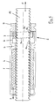
- FIG. 1 shows a first longitudinal section along the line BB through a spindle nut 1 with a safety nut 3 arranged in a receiving part 2.
- the spindle nut 1 is held in a nut receptacle 4 and positioned on an inner web 5 in the axial direction.
- a bush 6 is also held in the nut receptacle 4 and is positioned on the inner web 5 in the axial direction with respect to the spindle nut 1.
- the bushing 6 is held in the mother receptacle 4 with a holding piece 7.
- the safety nut 3 is positioned in the bush 6.
- the mother receptacle 4, bush 6 and holding piece 7 together form the receiving part 2.
- the inner web 5 has a first receiving part contact surface 8a on the safety nut side.
- the holding piece 7 also has a second receiving part contact surface 8b on the safety nut side.
- the safety nut 3 has a first nut contact surface 9a on the inside web side and a second mother contact surface 9b on the holding piece side. Both nut contact surfaces 9a and 9b are formed obliquely here at an angle of approximately 2 ° with respect to the axial direction (threaded axis of the safety nut 3).
- the receiving part contact surfaces 8a and 8b are orthogonal to the axial direction (thread axis of the spindle nut 1 and the threaded spindle).
- the safety nut 3 is held in the bush 6 by means of a part with a predetermined breaking point (cf. FIGS. 2 and 3) relative to the nut receptacle 4 and the spindle nut 1 in such a way that the nut contact surfaces 9a, 9b and do not touch the receiving part contact surfaces 8a, 8b and the safety nut 3 runs unloaded (with the spindle nut 1) when the predetermined breaking point is intact.
- Safety nut 3 and spindle nut 1 are thus 'synchronized' to a certain extent in normal operation
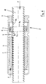
- FIG. 2 shows a second longitudinal section along the line AA through the spindle nut 1 with the assembled safety nut 3 in a manner similar to the illustration in FIG. 1.
- FIG. 3 shows a detailed view of C (without holding piece 7).
- a positioning cam 10 is additionally visible, with which the sleeve 6 is held in the nut receptacle 4 without rotation.
- two narrow-walled cam-like webs 11 are attached, which engage in longitudinal grooves or grooves 12 on the circumferential surface of the safety nut 3 and position it there without displacement and rotation.
- the webs 11 are designed as a predetermined breaking point.
- the longitudinal grooves 12 are dimensioned so that the load moment, which in the event of failure of the Spindle nut thread is transmitted via the safety nut, the webs 11 can break off, whereupon the safety nut 3 canted on the threaded spindle and subsequently stops the relative movement between the threaded spindle and the spindle nut.
- FIG. 4 is a schematic diagram of the operation of the safety nut 3 with the spindle nut thread 14 intact.
- the safety nut 3 is held in the nut receptacle 4 via the bushing 6 with respect to the spindle nut 1 without displacement and rotation.
- the safety nut 3 is 'synchronized' with the spindle nut 1, i.e. it runs with no load.
- the synchronization takes place via the relative positioning (distance and rotation) of the safety nut 3 relative to the spindle nut 1.
- the longitudinal grooves 12 on the safety nut 3 and the positioning cams 10 and the web 11 on the bush 6 serve (see FIG. 3).
- Tensile or compressive forces of the loads to be moved by the linear drive are transmitted directly to the threaded spindle 15 via the nut holder 4, the spindle nut 1 and the spindle nut thread 14.
- the shape of the safety nut 3 and the receiving part can ensure that the desired safety function is present both under tensile and compressive loads.
- FIG. 5 is a basic illustration of the functioning of the safety nut 3 in the case of a traction drive and with an open spindle nut thread 14.
- the threaded spindle 15 and the spindle nut 1 or the nut receptacle are pulled apart by the tensile load (F). Since it is assumed here that the spindle nut thread 14 has already failed, the web 11 (anti-rotation device and predetermined breaking point) on the bush 6 is also broken as a result of the suddenly acting load torque and the safety nut 3 is pressed against the holding piece 7.
- the load nut which continues to act, tries to turn the safety nut 3 further (which is also possible initially because the thread is not self-locking) and subsequently the safety nut 3 tilts on the threaded spindle 15 because of the necessary play and because of the crooked nut - Contact surface 9b and the 'straight' receiving part contact surface 8b come to lie against each other.
- the further relative movement between the threaded spindle 15 and the spindle nut 1 or the nut holder 4 is effectively stopped by the tilting.
- FIG. 6 is a schematic diagram of the functioning of the safety nut 3 in the case of a pressure drive and with an open spindle nut thread 14.
- the threaded spindle 15 and the spindle nut 1 or the nut holder are pressed against one another by the pressure load (F). Since it is assumed here that the spindle nut thread 14 has already failed, the web 11 (anti-rotation device and predetermined breaking point) on the bush 6 is also broken as a result of the suddenly acting load moment and the safety nut 3 is pressed against the inner web 5.
- the load nut 3 which continues to act tries to turn the safety nut 3 (which is also possible at first because the thread is not self-locking) and subsequently jams the safety nut 3 on the threaded spindle 15, because there is the necessary play and because the oblique nut contact surface 9a and the 'straight' receiving part contact surface 8a come to rest.
- the further relative movement between the threaded spindle 15 and the spindle nut 1 or the nut holder 4 is effectively stopped by the tilting.
- the inventive idea is based on the fact that (in the case of use) the safety nut is forcibly tilted. This is preferably done with an inclined contact surface on the safety nut, because here the contact surface is relatively easy to machine. It is obvious that the same effect can of course also be achieved if instead the contact surface of the part on which the safety nut rests is provided with an inclined contact surface. Therefore, the invention can be seen and implemented both in the design of the safety nut and in the design of the receiving part.
- the configuration thus allows the kinematic reversal of the application principle.
- the maximum functionality (safety function for pull and push drives) is obtained if there are at least two inclined contact surfaces. As in the example above, these can both be formed on the safety nut. It But both can also be formed on the receiving part and there is also the possibility of forming one on the safety nut and the other on the receiving part. The maximum functionality can therefore be achieved with different design forms of the combination of safety nut and receiving part.
- the forcible tilting of the safety nut can also be achieved by other means, for example with protruding cams or similar shapes attached at suitable locations.
Landscapes
- Engineering & Computer Science (AREA)
- General Engineering & Computer Science (AREA)
- Mechanical Engineering (AREA)
- Transmission Devices (AREA)
- Fluid-Damping Devices (AREA)
Abstract
Description
- Die Erfindung betrifft eine Sicherheitsmutter für einen Linearantrieb mit einer selbsthemmenden oder einer nicht-selbsthemmenden Gewindespindel nach Patentanspruch 1 sowie ein Aufnahmeteil für eine Sicherheitsmutter für einen Linearantrieb mit einer selbsthemmenden oder einer nicht-selbsthemmenden Gewindespindel nach Patentanspruch 2.
- Ferner betrifft die Erfindung auch die Kombination einer Sicherheitsmutter mit einem Aufnahmeteil für einen Linearantrieb mit einer selbsthemmenden oder einer nicht-selbsthemmenden Gewindespindel nach einem der Patentansprüche 3, 5 oder 6.
- Ferner betrifft die Erfindung auch einen Linearantrieb mit einer selbsthemmenden oder einer nicht-selbsthemmenden Gewindespindel und einer Sicherheitsmutter und einem Aufnahmeteil für eine Sicherheitsmutter nach Patentanspruch 7.
- Linearantriebe mit einem linear bewegbaren Schubrohr und einer im Schubrohr geführten und von einer Antriebseinheit angetriebenen Gewindespindel werden häufig verwendet, um Vorrichtungen oder Vorrichtungsteile linear um kurze Strecken zu verschieben oder um Klappen, Deckel und dergleichen zu öffnen und zu schliessen.
- Bei derartigen Linearantrieben kann man grössere Wirkungsgrade erzielen, indem Gewindespindeln mit so grossen Gewindesteigungen eingesetzt werden, dass die Selbsthemmungsgrenzen überschritten werden. Man spricht dann von nicht-selbsthemmenden Gewindespindeln. In der Folge müssen zwischen den Spindeln und den Antriebsachsen der Antriebseinheit zusätzliche Bauteile, wie beispielsweise Schlingfederbremsen (wrap spring clutches/brakes) eingesetzt werden, um zu verhindern, dass die vom Linearantrieb angehobene Last beim Abstellen des Antriebsmotors in der Antriebseinheit die Spindel wieder in der entgegengesetzten Richtung zu drehen vermag. Derartige Schlingfederbremsen sind bereits wohlbekannt und nicht Gegenstand der vorliegenden Erfindung. Die Einführung nicht-selbsthemmender Gewindespindeln bringt nun aber auch neue Probleme im Sicherheitsbereich, insbesondere bei Anwendungen bei denen eine ausgesprochene fail-safe Sicherheit gefordert ist, wie beispielsweise im Medizinalbereich bei Operationstischen oder Spitalbetten. Es geht darum, dass bei bestimmten 'kritischen' Bauteilen eine sehr hohe Sicherheit bezüglich sogenannter "Erstfehlerfälle" eingebaut sein muss. Es muss ein zweites Mittel vorhanden sein, das beim Ausfall des ersten Mittels (Erstfehlerfall) die betreffende Funktion übernimmt und sicherstellt.
- Die Gewindespindel eines gattungsgemässen Linearantriebes läuft üblicherweise in einer Spindelmutter. Über die Spindelmutter wird somit die zu verschiebende Last bewegt. Derartige Spindelmuttern sind häufig aus einem Kunststoff gefertigt und haben ein Innengewinde, das insbesondere bei hohen Belastungen auch hoher Abnutzung unterliegt, selbstverständlich aber auch anderen Effekten wie Alterung etc. Weil die ganze Last über dieses Innengewinde übertragen wird, muss eine Sicherung für den Fall vorhanden sein, dass dieses Gewinde durchbricht. Gängige Lösungen bei klassischen Linearantrieben mit selbsthemmenden Gewindespindeln bestehen darin, dass (von der Spindelmutter) etwas beabstandet eine Sicherheitsmutter (aus Metall) angebracht ist, die im Normalfall unbelastet mitläuft, bei einem Gewindebruch der Spindelmutter aber die ganze Last aufnehmen kann. Im Falle einer auf Druck belasteten Anwendung (z.B. beim Heben einer Last) ist die Sicherheitsmutter deshalb zwischen dem Spindelantrieb und der Spindelmutter angeordnet, um bei Bedarf die Last auffangen zu können. Lösungen mit Sicherheitsmuttern sind deshalb oft nur in einer Richtung wirkende Sicherheitseinrichtungen.
- Grundsätzlich könnten auch bei Linearantrieben mit nicht-selbsthemmenden Gewindespindeln 'konventionelle' Sicherheitsmuttern eingesetzt werden, sie hätten aber zur Folge, dass sie im Falle eines Gewindebruches der Spindelmutter die Bewegung der Last unter Umständen doch nicht aufhalten könnte, weil die Spindelmutter natürlich die gleichen nicht-selbsthemmenden Gewindeeigenschaften wie die Spindelmutter aufweist.
- Ziel der vorliegenden Erfindung ist deshalb, eine Lösung mit einer Sicherheitsmutter anzugeben, mit der die Bewegung der Last im Falle eines Gewindebruches der Spindelmutter vollständig aufgehalten wird.
- Diese Aufgabe wird durch die Merkmale in den unabhängigen Patentansprüchen 1, 2, 3, 5 und 7 gelöst.
- Die Lösung erfordert, dass zumindest eine Anlagefläche der Sicherheitsmutter oder eine Anlagefläche eines Aufnahmeteiles für die Sicherheitsmutter schief angeordnet ist, um im Fall eines Gewindebruches der Spindelmutter ein Verkanten der Sicherheitsmutter auf der Gewindespindel zu erreichen und durch die Verkantung die weitere Bewegung der Last aufzuhalten.
- Da das Lösungsprinzip die kinematische Umkehr erlaubt, kann das Teil, das die schief angeordnete Anlagefläche aufweist, entweder die Sicherheitsmutter selber oder das Aufnahmeteil für die Sicherheitsmutter sein.
- Der laststoppende Effekt im Falle eines Versagens des Gewindes der Spindelmutter kommt durch das Zusammenwirken der erfindungsgemäss komplementär ausgebildeten Sicherheitsmutter mit dem Aufnahmeteil für die Sicherheitsmutter zustande. Wird eine Sicherheitsmutter-Anlagefläche relativ zur Gewindeachse der Sicherheitsmutter schief ausgebildet, so muss die entsprechende komplementäre Aufnahmeteil-Anlagefläche relativ zur Achse der Gewindespindel orthogonal ausgebildet sein, und umgekehrt.
- Die erfindungsgemässe Sicherheitsmutter-Lösung kann sowohl bei Linearantrieben mit selbsthemmender Gewindespindel wie auch bei Linearantrieben mit nicht-selbsthemmender Gewindespindel eingesetzt werden. Im ersteren Fall ergibt sich sogar noch eine erhöhte Sicherheit, da die Selbsthemmungs-Eigenschaft und die Verkantungs-Eigenschaft im Einsatzfall gleichwirkend sind. Ausserdem ermöglicht diese dual-use Eigenschaft eine Vereinheitlichung im Sortiment.
- Die erfindungsgemässe Sicherheitsmutter-Lösung kann sowohl bei Druck- wie auch bei Zugbelastungen eingesetzt werden. Im Falle einer Druckbelastung muss an der der Spindelmutter zugewandten Seite mindestens eine Anlagefläche (entweder an der Sicherheitsmutter oder am Aufnahmeteil für die Sicherheitsmutter) schief ausgebildet sein. Im Falle einer Zugbelastung muss an der der Spindelmutter abgewandten Seite mindestens eine Anlagefläche (entweder an der Sicherheitsmutter oder am Aufnahmeteil für die Sicherheitsmutter) schief ausgebildet sein. Die Sicherheitsmutter-Lösung kann aber auch so ausgestaltet sein, dass die Sicherung sowohl bei Druck wie auch bei Zugbelastungen erfolgt. Es erfordert beispielsweise lediglich, dass beide Anlageflächen der Sicherheitsmutter schief zur Gewindeachse der Sicherheitsmutter verlaufen. Im Gegensatz zu Lösungen mit Sicherheitsmuttern bei Linearantrieben mit selbsthemmenden Gewindespindeln bedarf es in diesem Fall lediglich einer einzigen Sicherheitsmutter und sie kann grundsätzlich sogar auf einer beliebigen Seite der Spindelmutter angeordnet sein.
- Vorteilhaft wird die Sicherheitsmutter im Aufnahmeteil mittels eines Teiles mit einer Sollbruchstelle gegenüber der Spindelmutter verschiebungs- und verdrehungsfrei in einer Weise so gehalten, dass sich die Mutter-Anlageflächen und die Aufnahmeteil-Anlageflächen nicht berühren und die Sicherheitsmutter bei intakter Sollbruchstelle unbelastet (mit der Spindelmutter) mitläuft. Sicherheitsmutter und Spindelmutter sind somit im Normalbetrieb gewissermassen 'synchronisiert'.
- Zwischen der Sicherheitsmutter und der Gewindespindel muss Spiel vorhanden sein, um das Verkanten der Sicherheitsmutter beim Anliegen der Mutter-Anlagefläche an der Aufnahmeteil-Anlagefläche im Versagensfall des Spindelmutter-Gewindes, bzw. daraufhin in der Folge des Versagens an der Sollbruchstelle, zu ermöglichen.
- Im Weiteren kann das Aufnahmeteil für die Spindelmutter aus einem oder aus mehreren Teilen bestehen. Als fertigungstechnisch günstig hat sich erwiesen, für die Spindelmutter eine Spindelmutteraufnahme vorzusehen, in die eine geeignete Büchse mit einer Verdrehsicherung für die Sicherheitsmutter einsetzbar ist und wobei noch ein Abschluss- bzw. Haltestück vorgesehen ist. Das bislang lediglich allgemein erwähnte Aufnahmeteil wird dann durch die Kombination der Spindelmutteraufnahme mit der Büchse und dem Haltestück gebildet. An keinem dieser drei Teile müssen schief verlaufende (fertigungstechnisch schwierig herzustellende) Flächen angebracht werden.
- Im Folgenden wird eine erfindungsgemässe Sicherheitsmutter-Lösung für Druck- und Zugbelastung anhand eines Ausführungsbeispiels mit einer nicht-selbsthemmenden Gewindespindel mit Zeichnungen erläutert.
- In den Zeichnungen zeigen:
- Fig. 1
- einen ersten Längsschnitt entlang der Linie B-B durch eine Spindelmutter mit montierter Sicherheitsmutter,
- Fig. 2
- einen zweiten Längsschnitt entlang der Linie A-A durch eine Spindelmutter mit montierter Sicherheitsmutter,
- Fig. 3
- eine Detailansicht von C (ohne Haltestück),
- Fig. 4
- eine erste Prinzipdarstellung zur Funktionsweise mit intaktem Spindelmutter-Gewinde,
- Fig. 5
- eine zweite Prinzipdarstellung zur Funktionsweise mit durchbrochenem Spindelmutter-Gewinde bei ZugBelastung, und
- Fig. 6
- eine dritte Prinzipdarstellung zur Funktionsweise mit durchbrochenem Spindelmutter-Gewinde bei DruckBelastung.
- Die Figur 1 zeigt einen ersten Längsschnitt entlang der Linie B-B durch eine Spindelmutter 1 mit einer in einem Aufnahmeteil 2 angeordneten Sicherheitsmutter 3. Die Spindelmutter 1 ist dabei in einer Mutteraufnahme 4 gehalten und an einem Innensteg 5 in Axialrichtung positioniert. Auf der gegenüberliegenden Seite des Innenstegs 5 ist eine Büchse 6 ebenfalls in der Mutteraufnahme 4 gehalten und am Innensteg 5 in Axialrichtung gegenüber der Spindelmutter 1 positioniert. Mit einem Haltestück 7 wird die Büchse 6 in der Mutteraufnahme 4 gehalten. In der Büchse 6 ist die Sicherheitsmutter 3 positioniert. Mutteraufnahme 4, Büchse 6 und Haltestück 7 bilden hier zusammen das Aufnahmeteil 2.
- Der Innensteg 5 hat sicherheitsmutterseitig eine erste Aufnahmeteil-Anlagefläche 8a. Das Haltestück 7 hat ebenfalls sicherheitsmutterseitig eine zweite Aufnahmeteil-Anlagefläche 8b. Die Sicherheitsmutter 3 hat innenstegseitig eine erste Mutter-Anlagefläche 9a und haltestückseitig eine zweite Mutter-Anlagefläche 9b. Beide Mutter-Anlageflächen 9a und 9b sind hier in einem Winkel von ca. 2° gegenüber der Axialrichtung (Gewindeachse der Sicherheitsmutter 3) schief ausgebildet. Die Aufnahmeteil-Anlageflächen 8a und 8b sind hingegen gegenüber der Axialrichtung (Gewindeachse der Spindelmutter 1 und der Gewindespindel) orthogonal ausgebildet.
- Die Sicherheitsmutter 3 ist in der Büchse 6 mittels eines Teiles mit einer Sollbruchstelle (vergl. dazu Fig. 2 und 3) gegenüber der Mutteraufnahme 4 und der Spindelmutter 1 verschiebungs- und verdrehungsfrei in einer Weise gehalten, dass sich die Mutter-Anlageflächen 9a, 9b und die Aufnahmeteil-Anlageflächen 8a, 8b nicht berühren und die Sicherheitsmutter 3 bei intakter Sollbruchstelle unbelastet (mit der Spindelmutter 1) mitläuft. Sicherheitsmutter 3 und Spindelmutter 1 sind somit im Normalbetrieb gewissermassen 'synchronisiert'
- Die Figur 2 zeigt einen zweiten Längsschnitt entlang der Linie A-A durch die Spindelmutter 1 mit montierter Sicherheitsmutter 3 in ähnlicher Weise wie die Darstellung in Figur 1. Die Figur 3 zeigt eine Detailansicht von C (ohne Haltestück 7). In diesen beiden Figuren ist zusätzlich ein Positionierungsnocken 10 sichtbar, mit dem die Büchse 6 verdrehungsfrei in der Mutteraufnahme 4 gehalten ist. An der Büchse 6 sind zwei schmalwandige nockenartige Stege 11 angebracht, die in Längsrillen oder Längsnuten 12 an der Umfangfläche der Sicherheitsmutter 3 eingreifen und diese dort verschiebungsund verdrehungsfrei positionieren. Die Stege 11 sind als Sollbruchstelle ausgebildet. Die Längsnuten 12 sind so bemessen, dass das Lastmoment, das im Falle eines Versagens des Spindelmuttergewindes über die Sicherheitsmutter übertragen wird, die Stege 11 abzubrechen vermag, worauf die Sicherheitsmutter 3 auf der Gewindespindel verkantet und in der Folge die Relativbewegung zwischen Gewindespindel und Spindelmutter stoppt.
- In den Figuren 4, 5 und 6 wird die Funktionsweise der Sicherheitsmutter anhand des Ausführungsbeispiels näher erläutert.
- Die Figur 4 ist eine Prinzipdarstellung zur Funktionsweise der Sicherheitsmutter 3 bei intaktem Spindelmuttergewinde 14. Die Sicherheitsmutter 3 wird über die Büchse 6 in der Mutteraufnahme 4 bezüglich der Spindelmutter 1 verschiebungs- und verdrehungsfrei gehalten. In diesem Zustand ist die Sicherheitsmutter 3 gegenüber der Spindelmutter 1 'synchronisiert', d.h. sie läuft lastfrei mit. Die Synchronisierung erfolgt über die relative Positionierung (Abstand und Verdrehung) der Sicherheitsmutter 3 gegenüber der Spindelmutter 1. Zu diesem Zweck dienen die Längsnuten 12 an der Sicherheitsmutter 3 und der Positionierungsnocken 10 sowie der Steg 11 an der Büchse 6 (siehe Fig. 3). Zug- oder Druckkräfte der vom Linearantrieb zu bewegenden Lasten werden über die Mutteraufnahme 4, die Spindelmutter 1 und das Spindelmuttergewinde 14 direkt auf die Gewindespindel 15 übertragen.
- Die schief stehende Anlagefläche 9a der Sicherheitsmutter 3 und die 'gerade' (orthogonal zur Drehachse der Gewindespindel 15) verlaufende Anlagefläche 8a des Aufnahmeteils bzw. die schief stehende Anlagefläche 9b der Sicherheitsmutter 3 und die 'gerade' Anlagefläche 8b des Aufnahmeteils berühren sich bei intaktem Spindelmuttergewinde 14 nicht. Wie bereits früher erwähnt, kann durch die Formgebung von Sicherheitsmutter 3 und Aufnahmeteil erreicht werden, dass die angestrebte Sicherheitsfunktion sowohl bei Zug- wie auch bei Druckbelastung vorhanden ist. Hier wird sie erreicht indem beide Seiten der Sicherheitsmutter 3 mit schief verlaufenden Anlageflächen 9a, 9b versehen sind.
- Die Figur 5 ist eine Prinzipdarstellung zur Funktionsweise der Sicherheitsmutter 3 bei einem Zug-Antrieb und bei durchbrochenem Spindelmuttergewinde 14. Durch die Zugbelastung (F) werden die Gewindespindel 15 und die Spindelmutter 1 bzw. die Mutteraufnahme auseinandergezogen. Da hier angenommen wird, dass das Spindelmuttergewinde 14 bereits versagt hat, ist in der Folge der Steg 11 (Verdrehsicherung und Sollbruchstelle) an der Büchse 6 unter der Wirkung des plötzlich darauf einwirkenden Lastmomentes ebenfalls gebrochen und die Sicherheitsmutter 3 wird gegen das Haltestück 7 gedrückt. Das weiterhin wirkende Lastmoment versucht die Sicherheitsmutter 3 weiter zu drehen (was zunächst auch geht, weil das Gewinde ja nicht-selbsthemmend ist) und in der Folge verkantet sich die Sicherheitsmutter 3 an der Gewindespindel 15 weil das dazu notwendige Spiel besteht und weil die schiefe Mutter-Anlagefläche 9b und die 'gerade' Aufnahmeteil-Anlagefläche 8b aneinander zu liegen kommen. Durch das Verkanten wird die weitere Relativbewegung zwischen der Gewindespindel 15 und der Spindelmutter 1 bzw. der Mutteraufnahme 4 wirksam gestoppt.
- Die Figur 6 ist eine Prinzipdarstellung zur Funktionsweise der Sicherheitsmutter 3 bei einem Druck-Antrieb und bei durchbrochenem Spindelmuttergewinde 14. Durch die Druckbelastung (F) werden die Gewindespindel 15 und die Spindelmutter 1 bzw. die Mutteraufnahme gegeneinander gedrückt. Da hier angenommen wird, dass das Spindelmuttergewinde 14 bereits versagt hat, ist in der Folge der Steg 11 (Verdrehsicherung und Sollbruchstelle) an der Büchse 6 unter der Wirkung des plötzlich darauf einwirkenden Lastmomentes ebenfalls gebrochen und die Sicherheitsmutter 3 wird gegen den Innensteg 5 gedrückt. Das weiterhin wirkende Lastmoment versucht die Sicherheitsmutter 3 weiter zu drehen (was zunächst auch geht, weil das Gewinde ja nicht-selbsthemmend ist) und in der Folge verkantet sich die Sicherheitsmutter 3 an der Gewindespindel 15, weil das dazu notwendige Spiel besteht und weil die schiefe Mutter-Anlagefläche 9a und die 'gerade' Aufnahmeteil-Anlagefläche 8a aneinander zu liegen kommen. Durch das Verkanten wird die weitere Relativbewegung zwischen der Gewindespindel 15 und der Spindelmutter 1 bzw. der Mutteraufnahme 4 wirksam gestoppt.
- Es hat sich gezeigt, dass das Verkanten der Sicherheitsmutter 3 gewährleistet ist, wenn die Anlageflächen 9a oder 9b mit einer Schiefe von ca. 2° versehen werden und wenn zwischen der Gewindespindel 15 und der Sicherheitsmutter 3 ein Spiel von ca. 0.2 mm vorhanden ist (bei Gewindespindeln mit Durchmessern von ca. 20 mm) . Es hat sich weiterhin gezeigt, dass diese Sicherheitsmutter-Lösung sowohl fast unbelastet wie auch bei Volllast zuverlässig funktioniert.
- Prinzipiell beruht die erfinderische Idee also darauf, dass (im Einsatzfall) zwangsweise ein Verkanten der Sicherheitsmutter herbeigeführt wird. Dies geschieht vorzugsweise mit einer schrägen Anlagefläche an der Sicherheitsmutter, weil hier die Anlagefläche relativ einfach bearbeitbar ist. Offensichtlich ist, dass der gleiche Effekt natürlich auch erzielbar ist, wenn stattdessen die Anlagefläche des Teiles, an dem die Sicherheitsmutter anliegt, mit einer schrägen Anlagefläche versehen wird. Deshalb kann die Erfindung sowohl in der Ausgestaltung der Sicherheitsmutter wie auch in der Ausgestaltung des Aufnahmeteiles gesehen und realisiert werden.
- Die Ausgestaltung erlaubt somit die kinematische Umkehr des Anwendungsprinzips.
- Die maximale Funktionalität (Sicherheitsfunktion bei Zug- und bei Druck-Antrieb) erhält man, wenn mindestens zwei schräge Anlageflächen vorhanden sind. Diese können, wie im obigen Beispiel, beide an der Sicherheitsmutter ausgebildet sein. Es können aber auch beide am Aufnahmeteil ausgebildet sein und es besteht auch die Möglichkeit, die eine an der Sicherheitsmutter und die andere am Aufnahmeteil auszubilden. Die maximale Funktionalität ist deshalb mit verschiedenen konstruktiven Ausformungen der Kombination von Sicherheitsmutter und Aufnahmeteil erreichbar.
- Im Weiteren kann das zwangsweise Verkanten der Sicherheitsmutter auch noch mit anderen Mitteln erzielt werden, beispielsweise mit an geeigneten Stellen angebrachten vorstehenden Nocken oder ähnlichen Ausformungen.
-
- 1
- Spindelmutter
- 2
- Aufnahmeteil
- 3
- Sicherheitsmutter
- 4
- Mutteraufnahme
- 5
- Innensteg
- 6
- Büchse
- 7
- Haltestück
- 8a
- erste Aufnahmeteil-Anlagefläche
- 8b
- zweite Aufnahmeteil-Anlagefläche
- 9a
- erste Mutter-Anlagefläche
- 9b
- zweite Mutter-Anlagefläche
- 10
- Positionierungsnocken
- 11
- Steg
- 12
- Längsnute
- 13
- -
- 14
- Spindelmuttergewinde
- 15
- Gewindespindel
Claims (8)
- Sicherheitsmutter (3) für einen Linearantrieb mit selbsthemmender oder nicht-selbsthemmender Gewindespindel (15), dadurch gekennzeichnet, dass die Sicherheitsmutter (3) zumindest eine zur Gewindeachse der Sicherheitsmutter (3) schief angeordnete Mutter-Anlagefläche (9a, 9b) aufweist.
- Aufnahmeteil (2) für eine Sicherheitsmutter (3) für einen Linearantrieb mit selbsthemmender oder nicht-selbsthemmender Gewindespindel (15), dadurch gekennzeichnet, dass das Aufnahmeteil (2) zumindest eine zur Gewindeachse der Gewindespindel schief angeordnete Aufnahmeteil-Anlagefläche (8a, 8b) aufweist.
- Sicherheitsmutter (3) und Aufnahmeteil (2) für die Sicherheitsmutter für einen Linearantrieb mit selbsthemmender oder nicht-selbsthemmender Gewindespindel (15), dadurch gekennzeichnet, dass- die Sicherheitsmutter (3) zumindest eine zur Gewindeachse der Sicherheitsmutter schief angeordnete Mutter-Anlagefläche (9a, 9b) aufweist,- das Aufnahmeteil (2) für die Sicherheitsmutter zumindest eine zur Gewindeachse der Gewindespindel (15) orthogonale Aufnahmeteil-Anlagefläche (8a, 8b) für die Sicherheitsmutter aufweist.
- Sicherheitsmutter (3) und Aufnahmeteil (2) nach Patentanspruch 3, dadurch gekennzeichnet, dass die Sicherheitsmutter (3) zwei zur Gewindeachse der Sicherheitsmutter schief angeordnete Mutter-Anlageflächen (9a, 9b) aufweist.
- Sicherheitsmutter (3) und Aufnahmeteil (2) für die Sicherheitsmutter für einen Linearantrieb mit selbsthemmender oder nicht-selbsthemmender Gewindespindel (15), dadurch gekennzeichnet, dass- die Sicherheitsmutter (3) zumindest eine zur Gewindeachse der Sicherheitsmutter orthogonale Mutter-Anlagefläche (9a, 9b) aufweist,- das Aufnahmeteil (2) für die Sicherheitsmutter (3) zumindest eine zur Gewindeachse der Gewindespindel (15) schief angeordnete Aufnahmeteil-Anlagefläche (8a, 8b) für die Sicherheitsmutter aufweist.
- Sicherheitsmutter (3) und Aufnahmeteil (2) für die Sicherheitsmutter für einen Linearantrieb mit selbsthemmender oder nicht-selbsthemmender Gewindespindel (15), dadurch gekennzeichnet, dass die Sicherheitsmutter (3) oder das Aufnahmeteil (2) für die Sicherheitsmutter zumindest ein Mittel wie eine nockenartige Ausformung oder einen vorstehenden Absatz zur Erzielung einer Verkantung der Sicherheitsmutter aufweist.
- Linearantrieb mit einer selbsthemmenden oder einer nicht-selbsthemmenden Gewindespindel (15) und einer Sicherheitsmutter (3), wobei- die Gewindespindel (15) eine Spindelmutter (1) und ein mit der Spindelmutter drehfest verbundenes Aufnahmeteil (2) für die Sicherheitsmutter antreibt,- die Sicherheitsmutter (3) eine erste und eine zweite Mutter-Anlagefläche (9a, 9b) aufweist,- das Aufnahmeteil (2) eine erste und eine zweite Aufnahmeteil-Anlagefläche (8a, 8b) aufweist,- die Sicherheitsmutter (3) im Aufnahmeteil (2) an einer Sollbruchstelle gegenüber der Spindelmutter (1) verschiebungs- und verdrehungsfrei in einer Weise gehalten ist, dass sich die Mutter-Anlageflächen (9a, 9b) und die Aufnahmeteil-Anlageflächen (8a, 8b) nicht berühren und die Sicherheitsmutter (3) bei intakter Sollbruchstelle unbelastet mit der Spindelmutter (1) mitläuft,- die Sicherheitsmutter (3) zumindest eine zur Gewindeachse der Sicherheitsmutter schief angeordnete Mutter-Anlagefläche (9a, 9b) aufweist und das Aufnahmeteil (2) zumindest eine zur Gewindeachse der Gewindespindel orthogonale und der zumindest einen Mutter-Anlagefläche (9a, 9b) zugewandte Aufnahmeteil-Anlagefläche (8a, 8b) aufweist, oder aber die Sicherheitsmutter (3) zumindest eine zur Gewindeachse der Sicherheitsmutter orthogonale Mutter-Anlagefläche (9a, 9b) aufweist und das Aufnahmeteil (2) zumindest eine zur Gewindeachse der Gewindespindel schief angeordnete und der zumindest einen Mutter-Anlagefläche (9a, 9b) zugewandte Aufnahmeteil-Anlagefläche (8a, 8b) aufweist, und- zwischen der Sicherheitsmutter (3) und der Gewindespindel (15) Spiel vorhanden ist, das eine Verkantung der Sicherheitsmutter (3) beim Anliegen der Mutter-Anlagefläche (9a, 9b) an der Aufnahmeteil-Anlagefläche (8a, 8b) im Falle des Versagens der Sollbruchstelle ermöglicht.
- Linearantrieb nach Patentanspruch 7, dadurch gekennzeichnet, dass die Sicherheitsmutter (3) entlang der Umfangfläche Längsrillen oder Längsnuten (12) aufweist, eine mit dem Aufnahmeteil (2) drehfest verbundene Büchse (6) vorhanden ist, in der die Sicherheitsmutter (3) gegenüber der Spindelmutter (1) positioniert ist und ein vorstehender, die Sollbruchstelle bildender nockenartiger Steg (11) an der Büchse (6) in eine der Längsrillen oder Längsnuten (12) der Sicherheitsmutter (3) eingreift.
Applications Claiming Priority (2)
| Application Number | Priority Date | Filing Date | Title |
|---|---|---|---|
| CH4452003 | 2003-03-19 | ||
| CH4452003 | 2003-03-19 |
Publications (2)
| Publication Number | Publication Date |
|---|---|
| EP1460311A1 true EP1460311A1 (de) | 2004-09-22 |
| EP1460311B1 EP1460311B1 (de) | 2006-05-17 |
Family
ID=32778579
Family Applications (1)
| Application Number | Title | Priority Date | Filing Date |
|---|---|---|---|
| EP04005859A Expired - Lifetime EP1460311B1 (de) | 2003-03-19 | 2004-03-12 | Sicherheitsmutter und Aufnahmeteil für eine Sicherheitsmutter für einen Linearantrieb |
Country Status (4)
| Country | Link |
|---|---|
| EP (1) | EP1460311B1 (de) |
| AT (1) | ATE326654T1 (de) |
| DE (1) | DE502004000559D1 (de) |
| DK (1) | DK1460311T3 (de) |
Cited By (2)
| Publication number | Priority date | Publication date | Assignee | Title |
|---|---|---|---|---|
| WO2006034711A1 (en) * | 2004-09-29 | 2006-04-06 | Linak A/S | A linear actuator |
| EP2581698B1 (de) | 2011-10-12 | 2017-01-11 | Krauss-Maffei Wegmann GmbH & Co. KG | Spürvorrichtung für Bodenspürungen aus dem Inneren eines Fahrzeugs und Verfahren zum Bodenspüren |
Citations (3)
| Publication number | Priority date | Publication date | Assignee | Title |
|---|---|---|---|---|
| DE29506066U1 (de) * | 1995-04-12 | 1995-07-13 | Hännig, Wilfried, 59063 Hamm | Gewinde-Bruchsicherung für vertikal wirkende Bewegungsgewinde |
| US5918505A (en) * | 1994-12-23 | 1999-07-06 | Linak A/S | Linear actuator and method of making a linear actuator |
| EP0995714A1 (de) * | 1998-10-23 | 2000-04-26 | Alltec GmbH | Sicherheitseinrichtung für einen linearen Gewindetrieb |
-
2004
- 2004-03-12 AT AT04005859T patent/ATE326654T1/de not_active IP Right Cessation
- 2004-03-12 DE DE502004000559T patent/DE502004000559D1/de not_active Expired - Lifetime
- 2004-03-12 EP EP04005859A patent/EP1460311B1/de not_active Expired - Lifetime
- 2004-03-12 DK DK04005859T patent/DK1460311T3/da active
Patent Citations (3)
| Publication number | Priority date | Publication date | Assignee | Title |
|---|---|---|---|---|
| US5918505A (en) * | 1994-12-23 | 1999-07-06 | Linak A/S | Linear actuator and method of making a linear actuator |
| DE29506066U1 (de) * | 1995-04-12 | 1995-07-13 | Hännig, Wilfried, 59063 Hamm | Gewinde-Bruchsicherung für vertikal wirkende Bewegungsgewinde |
| EP0995714A1 (de) * | 1998-10-23 | 2000-04-26 | Alltec GmbH | Sicherheitseinrichtung für einen linearen Gewindetrieb |
Cited By (5)
| Publication number | Priority date | Publication date | Assignee | Title |
|---|---|---|---|---|
| WO2006034711A1 (en) * | 2004-09-29 | 2006-04-06 | Linak A/S | A linear actuator |
| CN100535478C (zh) * | 2004-09-29 | 2009-09-02 | 利纳克有限公司 | 线性致动器 |
| US7685898B2 (en) | 2004-09-29 | 2010-03-30 | Linak A/S | Linear actuator |
| AU2005289197B2 (en) * | 2004-09-29 | 2011-02-03 | Linak A/S | A linear actuator |
| EP2581698B1 (de) | 2011-10-12 | 2017-01-11 | Krauss-Maffei Wegmann GmbH & Co. KG | Spürvorrichtung für Bodenspürungen aus dem Inneren eines Fahrzeugs und Verfahren zum Bodenspüren |
Also Published As
| Publication number | Publication date |
|---|---|
| ATE326654T1 (de) | 2006-06-15 |
| EP1460311B1 (de) | 2006-05-17 |
| DK1460311T3 (da) | 2006-09-18 |
| DE502004000559D1 (de) | 2006-06-22 |
Similar Documents
| Publication | Publication Date | Title |
|---|---|---|
| DE102007042953B4 (de) | Orthopädisches Haltesystem | |
| EP2325502B1 (de) | Anordnung und Verfahren zum Verbinden eines Zubehörteils mit einem Operationstisch | |
| EP2241527B1 (de) | Anschlussvorrichtung | |
| DE19931837B4 (de) | Schraubverbindung für Scharnierteile | |
| DE102013202436A1 (de) | Lenksäulenteleskop und E/A-Verriegelungsvorrichtung | |
| EP3990804B1 (de) | Spielfreies planetenradgetriebe | |
| DE10348320A1 (de) | Fangmutter | |
| DE69934409T2 (de) | Werkzeug und verfahren zum abscheren von bolzen | |
| EP1790437A2 (de) | Vorrichtung zum Einpressen eines auf einer Radnabe sitzenden Radlagers | |
| EP2872789B1 (de) | Scheibenbremse für ein nutzfahrzeug | |
| DE102019108382A1 (de) | Gehäuseoberteil für Hochdruckfilter und Hochdruckfilter | |
| EP1460311B1 (de) | Sicherheitsmutter und Aufnahmeteil für eine Sicherheitsmutter für einen Linearantrieb | |
| EP0995714A1 (de) | Sicherheitseinrichtung für einen linearen Gewindetrieb | |
| EP1674764B1 (de) | Gewindemuttereinrichtung für eine Linearantriebsvorrichtung | |
| WO2018065898A1 (de) | Vorspannelementdruckschraube und vorspannelement mit mehreren solchen vorspannelementdruckschrauben sowie vorspannschraubenkörperelement mit mehreren solchen vorspannelementdruckschrauben | |
| EP0509267B1 (de) | Spannelement, enthaltend eine Schnellzustellvorrichtung kombiniert mit einem Kraftverstärker | |
| EP0929268B1 (de) | Palatinalsplitschraube | |
| EP1400190B1 (de) | Elektromotorischer Möbelantrieb | |
| DE202004009839U1 (de) | Verstellantrieb | |
| EP2767730A1 (de) | Verstellvorrichtung | |
| DE102004061244A1 (de) | Kraftübertragungsmechanismus, der zum Verhindern eines Bruchs einer Drehwelle in der Lage ist | |
| DE102019104125B4 (de) | Kugelgewindetrieb mit Verdrehsicherung | |
| DE102010010209B4 (de) | Matrizenscheibe | |
| WO2000020766A1 (de) | Schraube und schraubendreher für eine abrutschsichere schraube/ schraubendreher-paarung | |
| EP3747393A1 (de) | Orthodontische dehnschraube |
Legal Events
| Date | Code | Title | Description |
|---|---|---|---|
| PUAI | Public reference made under article 153(3) epc to a published international application that has entered the european phase |
Free format text: ORIGINAL CODE: 0009012 |
|
| AK | Designated contracting states |
Kind code of ref document: A1 Designated state(s): AT BE BG CH CY CZ DE DK EE ES FI FR GB GR HU IE IT LI LU MC NL PL PT RO SE SI SK TR |
|
| AX | Request for extension of the european patent |
Extension state: AL LT LV MK |
|
| 17P | Request for examination filed |
Effective date: 20040921 |
|
| 17Q | First examination report despatched |
Effective date: 20050322 |
|
| AKX | Designation fees paid |
Designated state(s): AT BE BG CH CY CZ DE DK EE ES FI FR GB GR HU IE IT LI LU MC NL PL PT RO SE SI SK TR |
|
| GRAP | Despatch of communication of intention to grant a patent |
Free format text: ORIGINAL CODE: EPIDOSNIGR1 |
|
| GRAS | Grant fee paid |
Free format text: ORIGINAL CODE: EPIDOSNIGR3 |
|
| GRAA | (expected) grant |
Free format text: ORIGINAL CODE: 0009210 |
|
| AK | Designated contracting states |
Kind code of ref document: B1 Designated state(s): AT BE BG CH CY CZ DE DK EE ES FI FR GB GR HU IE IT LI LU MC NL PL PT RO SE SI SK TR |
|
| PG25 | Lapsed in a contracting state [announced via postgrant information from national office to epo] |
Ref country code: CZ Free format text: LAPSE BECAUSE OF FAILURE TO SUBMIT A TRANSLATION OF THE DESCRIPTION OR TO PAY THE FEE WITHIN THE PRESCRIBED TIME-LIMIT Effective date: 20060517 Ref country code: FI Free format text: LAPSE BECAUSE OF FAILURE TO SUBMIT A TRANSLATION OF THE DESCRIPTION OR TO PAY THE FEE WITHIN THE PRESCRIBED TIME-LIMIT Effective date: 20060517 Ref country code: IT Free format text: LAPSE BECAUSE OF FAILURE TO SUBMIT A TRANSLATION OF THE DESCRIPTION OR TO PAY THE FEE WITHIN THE PRESCRIBED TIME-LIMIT;WARNING: LAPSES OF ITALIAN PATENTS WITH EFFECTIVE DATE BEFORE 2007 MAY HAVE OCCURRED AT ANY TIME BEFORE 2007. THE CORRECT EFFECTIVE DATE MAY BE DIFFERENT FROM THE ONE RECORDED. Effective date: 20060517 Ref country code: NL Free format text: LAPSE BECAUSE OF FAILURE TO SUBMIT A TRANSLATION OF THE DESCRIPTION OR TO PAY THE FEE WITHIN THE PRESCRIBED TIME-LIMIT Effective date: 20060517 Ref country code: SI Free format text: LAPSE BECAUSE OF FAILURE TO SUBMIT A TRANSLATION OF THE DESCRIPTION OR TO PAY THE FEE WITHIN THE PRESCRIBED TIME-LIMIT Effective date: 20060517 Ref country code: RO Free format text: LAPSE BECAUSE OF FAILURE TO SUBMIT A TRANSLATION OF THE DESCRIPTION OR TO PAY THE FEE WITHIN THE PRESCRIBED TIME-LIMIT Effective date: 20060517 Ref country code: PL Free format text: LAPSE BECAUSE OF FAILURE TO SUBMIT A TRANSLATION OF THE DESCRIPTION OR TO PAY THE FEE WITHIN THE PRESCRIBED TIME-LIMIT Effective date: 20060517 Ref country code: SK Free format text: LAPSE BECAUSE OF FAILURE TO SUBMIT A TRANSLATION OF THE DESCRIPTION OR TO PAY THE FEE WITHIN THE PRESCRIBED TIME-LIMIT Effective date: 20060517 Ref country code: IE Free format text: LAPSE BECAUSE OF FAILURE TO SUBMIT A TRANSLATION OF THE DESCRIPTION OR TO PAY THE FEE WITHIN THE PRESCRIBED TIME-LIMIT Effective date: 20060517 |
|
| REG | Reference to a national code |
Ref country code: GB Ref legal event code: FG4D Free format text: NOT ENGLISH |
|
| REG | Reference to a national code |
Ref country code: CH Ref legal event code: EP |
|
| REG | Reference to a national code |
Ref country code: IE Ref legal event code: FG4D Free format text: LANGUAGE OF EP DOCUMENT: GERMAN |
|
| REF | Corresponds to: |
Ref document number: 502004000559 Country of ref document: DE Date of ref document: 20060622 Kind code of ref document: P |
|
| REG | Reference to a national code |
Ref country code: DE Ref legal event code: R096 Ref document number: 502004000559 Country of ref document: DE Effective date: 20060622 |
|
| GBT | Gb: translation of ep patent filed (gb section 77(6)(a)/1977) |
Effective date: 20060712 |
|
| PG25 | Lapsed in a contracting state [announced via postgrant information from national office to epo] |
Ref country code: ES Free format text: LAPSE BECAUSE OF FAILURE TO SUBMIT A TRANSLATION OF THE DESCRIPTION OR TO PAY THE FEE WITHIN THE PRESCRIBED TIME-LIMIT Effective date: 20060828 |
|
| REG | Reference to a national code |
Ref country code: SE Ref legal event code: TRGR |
|
| REG | Reference to a national code |
Ref country code: DK Ref legal event code: T3 |
|
| REG | Reference to a national code |
Ref country code: CH Ref legal event code: NV Representative=s name: R. A. EGLI & CO. PATENTANWAELTE |
|
| PG25 | Lapsed in a contracting state [announced via postgrant information from national office to epo] |
Ref country code: PT Free format text: LAPSE BECAUSE OF FAILURE TO SUBMIT A TRANSLATION OF THE DESCRIPTION OR TO PAY THE FEE WITHIN THE PRESCRIBED TIME-LIMIT Effective date: 20061017 |
|
| NLV1 | Nl: lapsed or annulled due to failure to fulfill the requirements of art. 29p and 29m of the patents act | ||
| ET | Fr: translation filed | ||
| REG | Reference to a national code |
Ref country code: IE Ref legal event code: FD4D |
|
| PLBE | No opposition filed within time limit |
Free format text: ORIGINAL CODE: 0009261 |
|
| STAA | Information on the status of an ep patent application or granted ep patent |
Free format text: STATUS: NO OPPOSITION FILED WITHIN TIME LIMIT |
|
| 26N | No opposition filed |
Effective date: 20070220 |
|
| REG | Reference to a national code |
Ref country code: DE Ref legal event code: R097 Ref document number: 502004000559 Country of ref document: DE Effective date: 20070220 |
|
| BERE | Be: lapsed |
Owner name: A.B. SKF Effective date: 20070331 |
|
| PG25 | Lapsed in a contracting state [announced via postgrant information from national office to epo] |
Ref country code: BE Free format text: LAPSE BECAUSE OF NON-PAYMENT OF DUE FEES Effective date: 20070331 |
|
| PG25 | Lapsed in a contracting state [announced via postgrant information from national office to epo] |
Ref country code: MC Free format text: LAPSE BECAUSE OF NON-PAYMENT OF DUE FEES Effective date: 20070331 |
|
| PG25 | Lapsed in a contracting state [announced via postgrant information from national office to epo] |
Ref country code: GR Free format text: LAPSE BECAUSE OF FAILURE TO SUBMIT A TRANSLATION OF THE DESCRIPTION OR TO PAY THE FEE WITHIN THE PRESCRIBED TIME-LIMIT Effective date: 20060818 |
|
| PG25 | Lapsed in a contracting state [announced via postgrant information from national office to epo] |
Ref country code: BG Free format text: LAPSE BECAUSE OF FAILURE TO SUBMIT A TRANSLATION OF THE DESCRIPTION OR TO PAY THE FEE WITHIN THE PRESCRIBED TIME-LIMIT Effective date: 20060817 Ref country code: AT Free format text: LAPSE BECAUSE OF NON-PAYMENT OF DUE FEES Effective date: 20070312 |
|
| PG25 | Lapsed in a contracting state [announced via postgrant information from national office to epo] |
Ref country code: EE Free format text: LAPSE BECAUSE OF FAILURE TO SUBMIT A TRANSLATION OF THE DESCRIPTION OR TO PAY THE FEE WITHIN THE PRESCRIBED TIME-LIMIT Effective date: 20060517 |
|
| PG25 | Lapsed in a contracting state [announced via postgrant information from national office to epo] |
Ref country code: CY Free format text: LAPSE BECAUSE OF FAILURE TO SUBMIT A TRANSLATION OF THE DESCRIPTION OR TO PAY THE FEE WITHIN THE PRESCRIBED TIME-LIMIT Effective date: 20060517 Ref country code: LU Free format text: LAPSE BECAUSE OF NON-PAYMENT OF DUE FEES Effective date: 20070312 |
|
| PG25 | Lapsed in a contracting state [announced via postgrant information from national office to epo] |
Ref country code: TR Free format text: LAPSE BECAUSE OF FAILURE TO SUBMIT A TRANSLATION OF THE DESCRIPTION OR TO PAY THE FEE WITHIN THE PRESCRIBED TIME-LIMIT Effective date: 20060517 Ref country code: HU Free format text: LAPSE BECAUSE OF FAILURE TO SUBMIT A TRANSLATION OF THE DESCRIPTION OR TO PAY THE FEE WITHIN THE PRESCRIBED TIME-LIMIT Effective date: 20061118 |
|
| PGFP | Annual fee paid to national office [announced via postgrant information from national office to epo] |
Ref country code: DK Payment date: 20100310 Year of fee payment: 7 |
|
| PGFP | Annual fee paid to national office [announced via postgrant information from national office to epo] |
Ref country code: FR Payment date: 20100402 Year of fee payment: 7 |
|
| PGFP | Annual fee paid to national office [announced via postgrant information from national office to epo] |
Ref country code: GB Payment date: 20100322 Year of fee payment: 7 |
|
| PGFP | Annual fee paid to national office [announced via postgrant information from national office to epo] |
Ref country code: CH Payment date: 20100428 Year of fee payment: 7 |
|
| PGFP | Annual fee paid to national office [announced via postgrant information from national office to epo] |
Ref country code: SE Payment date: 20100312 Year of fee payment: 7 |
|
| REG | Reference to a national code |
Ref country code: DK Ref legal event code: EBP Ref country code: CH Ref legal event code: PL |
|
| REG | Reference to a national code |
Ref country code: SE Ref legal event code: EUG |
|
| GBPC | Gb: european patent ceased through non-payment of renewal fee |
Effective date: 20110312 |
|
| REG | Reference to a national code |
Ref country code: FR Ref legal event code: ST Effective date: 20111130 |
|
| PG25 | Lapsed in a contracting state [announced via postgrant information from national office to epo] |
Ref country code: FR Free format text: LAPSE BECAUSE OF NON-PAYMENT OF DUE FEES Effective date: 20110331 Ref country code: LI Free format text: LAPSE BECAUSE OF NON-PAYMENT OF DUE FEES Effective date: 20110331 Ref country code: CH Free format text: LAPSE BECAUSE OF NON-PAYMENT OF DUE FEES Effective date: 20110331 |
|
| PG25 | Lapsed in a contracting state [announced via postgrant information from national office to epo] |
Ref country code: GB Free format text: LAPSE BECAUSE OF NON-PAYMENT OF DUE FEES Effective date: 20110312 |
|
| PG25 | Lapsed in a contracting state [announced via postgrant information from national office to epo] |
Ref country code: DK Free format text: LAPSE BECAUSE OF NON-PAYMENT OF DUE FEES Effective date: 20110331 |
|
| PG25 | Lapsed in a contracting state [announced via postgrant information from national office to epo] |
Ref country code: SE Free format text: LAPSE BECAUSE OF NON-PAYMENT OF DUE FEES Effective date: 20110313 |
|
| REG | Reference to a national code |
Ref country code: DE Ref legal event code: R082 Ref document number: 502004000559 Country of ref document: DE Representative=s name: HEYERHOFF GEIGER GMBH & CO. KG, DE Ref country code: DE Ref legal event code: R082 Ref document number: 502004000559 Country of ref document: DE Representative=s name: HEYERHOFF GEIGER & PARTNER PATENTANWAELTE PART, DE |
|
| REG | Reference to a national code |
Ref country code: DE Ref legal event code: R081 Ref document number: 502004000559 Country of ref document: DE Owner name: SCHAEFFLER TECHNOLOGIES AG & CO. KG, DE Free format text: FORMER OWNER: AB SKF, GOETEBORG/GOTENBURG, SE Ref country code: DE Ref legal event code: R082 Ref document number: 502004000559 Country of ref document: DE Representative=s name: HEYERHOFF GEIGER & PARTNER PATENTANWAELTE PART, DE Ref country code: DE Ref legal event code: R081 Ref document number: 502004000559 Country of ref document: DE Owner name: EWELLIX AB, SE Free format text: FORMER OWNER: AB SKF, GOETEBORG/GOTENBURG, SE |
|
| PGFP | Annual fee paid to national office [announced via postgrant information from national office to epo] |
Ref country code: DE Payment date: 20230322 Year of fee payment: 20 |
|
| P01 | Opt-out of the competence of the unified patent court (upc) registered |
Effective date: 20230514 |
|
| REG | Reference to a national code |
Ref country code: DE Ref legal event code: R071 Ref document number: 502004000559 Country of ref document: DE |
|
| REG | Reference to a national code |
Ref country code: DE Ref legal event code: R082 Ref document number: 502004000559 Country of ref document: DE Ref country code: DE Ref legal event code: R081 Ref document number: 502004000559 Country of ref document: DE Owner name: SCHAEFFLER TECHNOLOGIES AG & CO. KG, DE Free format text: FORMER OWNER: EWELLIX AB, GOETEBORG, SE |