EP1460300B1 - Method of operation for parking brakes used with electromechanically actuated disc brakes. - Google Patents
Method of operation for parking brakes used with electromechanically actuated disc brakes. Download PDFInfo
- Publication number
- EP1460300B1 EP1460300B1 EP20040101130 EP04101130A EP1460300B1 EP 1460300 B1 EP1460300 B1 EP 1460300B1 EP 20040101130 EP20040101130 EP 20040101130 EP 04101130 A EP04101130 A EP 04101130A EP 1460300 B1 EP1460300 B1 EP 1460300B1
- Authority
- EP
- European Patent Office
- Prior art keywords
- locking
- mechanical
- determined
- angular
- rotational element
- Prior art date
- Legal status (The legal status is an assumption and is not a legal conclusion. Google has not performed a legal analysis and makes no representation as to the accuracy of the status listed.)
- Expired - Lifetime
Links
- 238000000034 method Methods 0.000 title claims description 9
- 238000001514 detection method Methods 0.000 claims description 5
- 230000005540 biological transmission Effects 0.000 description 4
- 230000004913 activation Effects 0.000 description 3
- 230000000903 blocking effect Effects 0.000 description 1
- 238000001816 cooling Methods 0.000 description 1
Images

Classifications
-
- F—MECHANICAL ENGINEERING; LIGHTING; HEATING; WEAPONS; BLASTING
- F16—ENGINEERING ELEMENTS AND UNITS; GENERAL MEASURES FOR PRODUCING AND MAINTAINING EFFECTIVE FUNCTIONING OF MACHINES OR INSTALLATIONS; THERMAL INSULATION IN GENERAL
- F16D—COUPLINGS FOR TRANSMITTING ROTATION; CLUTCHES; BRAKES
- F16D65/00—Parts or details
- F16D65/14—Actuating mechanisms for brakes; Means for initiating operation at a predetermined position
- F16D65/16—Actuating mechanisms for brakes; Means for initiating operation at a predetermined position arranged in or on the brake
- F16D65/18—Actuating mechanisms for brakes; Means for initiating operation at a predetermined position arranged in or on the brake adapted for drawing members together, e.g. for disc brakes
-
- F—MECHANICAL ENGINEERING; LIGHTING; HEATING; WEAPONS; BLASTING
- F16—ENGINEERING ELEMENTS AND UNITS; GENERAL MEASURES FOR PRODUCING AND MAINTAINING EFFECTIVE FUNCTIONING OF MACHINES OR INSTALLATIONS; THERMAL INSULATION IN GENERAL
- F16D—COUPLINGS FOR TRANSMITTING ROTATION; CLUTCHES; BRAKES
- F16D66/00—Arrangements for monitoring working conditions, e.g. wear, temperature
- F16D2066/003—Position, angle or speed
-
- F—MECHANICAL ENGINEERING; LIGHTING; HEATING; WEAPONS; BLASTING
- F16—ENGINEERING ELEMENTS AND UNITS; GENERAL MEASURES FOR PRODUCING AND MAINTAINING EFFECTIVE FUNCTIONING OF MACHINES OR INSTALLATIONS; THERMAL INSULATION IN GENERAL
- F16D—COUPLINGS FOR TRANSMITTING ROTATION; CLUTCHES; BRAKES
- F16D66/00—Arrangements for monitoring working conditions, e.g. wear, temperature
- F16D2066/005—Force, torque, stress or strain
-
- F—MECHANICAL ENGINEERING; LIGHTING; HEATING; WEAPONS; BLASTING
- F16—ENGINEERING ELEMENTS AND UNITS; GENERAL MEASURES FOR PRODUCING AND MAINTAINING EFFECTIVE FUNCTIONING OF MACHINES OR INSTALLATIONS; THERMAL INSULATION IN GENERAL
- F16D—COUPLINGS FOR TRANSMITTING ROTATION; CLUTCHES; BRAKES
- F16D2121/00—Type of actuator operation force
- F16D2121/18—Electric or magnetic
- F16D2121/24—Electric or magnetic using motors
-
- F—MECHANICAL ENGINEERING; LIGHTING; HEATING; WEAPONS; BLASTING
- F16—ENGINEERING ELEMENTS AND UNITS; GENERAL MEASURES FOR PRODUCING AND MAINTAINING EFFECTIVE FUNCTIONING OF MACHINES OR INSTALLATIONS; THERMAL INSULATION IN GENERAL
- F16D—COUPLINGS FOR TRANSMITTING ROTATION; CLUTCHES; BRAKES
- F16D2125/00—Components of actuators
- F16D2125/18—Mechanical mechanisms
- F16D2125/20—Mechanical mechanisms converting rotation to linear movement or vice versa
- F16D2125/34—Mechanical mechanisms converting rotation to linear movement or vice versa acting in the direction of the axis of rotation
- F16D2125/40—Screw-and-nut
-
- F—MECHANICAL ENGINEERING; LIGHTING; HEATING; WEAPONS; BLASTING
- F16—ENGINEERING ELEMENTS AND UNITS; GENERAL MEASURES FOR PRODUCING AND MAINTAINING EFFECTIVE FUNCTIONING OF MACHINES OR INSTALLATIONS; THERMAL INSULATION IN GENERAL
- F16D—COUPLINGS FOR TRANSMITTING ROTATION; CLUTCHES; BRAKES
- F16D2127/00—Auxiliary mechanisms
- F16D2127/06—Locking mechanisms, e.g. acting on actuators, on release mechanisms or on force transmission mechanisms
-
- F—MECHANICAL ENGINEERING; LIGHTING; HEATING; WEAPONS; BLASTING
- F16—ENGINEERING ELEMENTS AND UNITS; GENERAL MEASURES FOR PRODUCING AND MAINTAINING EFFECTIVE FUNCTIONING OF MACHINES OR INSTALLATIONS; THERMAL INSULATION IN GENERAL
- F16D—COUPLINGS FOR TRANSMITTING ROTATION; CLUTCHES; BRAKES
- F16D2129/00—Type of operation source for auxiliary mechanisms
- F16D2129/06—Electric or magnetic
- F16D2129/08—Electromagnets
Definitions
- the invention relates to a method for operating an electromechanically actuated disc brake for motor vehicles with a parking brake device and an actuating unit which has an electromechanical drive unit for generating a braking force, of which at least one mechanical-rotary element can be locked by a locking unit with a locking element, and with a Clamping force sensor or a sensor for detecting the angular position of the mechanical-rotary element.
- Such electromechanically actuated disc brake is from the Patent Application DE 198 07 328 A1 known.
- the previously known disc brake has a spindle / nut gear arrangement, the spindle is rotatably connected to a ring gear.
- a pawl is provided as a locking element.
- the actuated to lock the rotor pawl does not cause an immediate locking / blocking in each angular position of the rotor.
- the rotor rotates back through a so-called activation angle counter to the direction that would correspond to an increase in the application force until the pawl reaches the lock position has reached.
- this has the consequence that the set clamping force is reduced, which is considered disadvantageous.
- This object is achieved in that the mechanical-rotary element is rotated by setting the required for a parking brake application force before actuation of the locking element by a certain angle in that direction, which corresponds to an increase in the application force.
- the locking unit is formed by a pawl and a gear whose pitch angle determines the angular amount.
- the angular amount of an additional Zuspannkraftbetrag is determined, which is determined by the number of locking positions of the locking unit and a security amount. It is provided that the amount of security is determined by means of the stiffness of the caliper and the actuating unit, and with the determined or estimated temperature of the disc brake.
- the locking positions of Locking unit determined by means of the sensor for detecting the angular position of the mechanical-rotatory element and stored in an electronic storage medium and the angular amount for further rotation of the mechanical-rotary element from the comparison of the current angular position of the mechanical-rotary element and the stored locking positions determined.
- electromechanically actuated disc brake on which the inventive method can be performed is formed of an actuating unit and a merely schematically indicated caliper which is slidably mounted in a stationary holder, not shown.
- a pair of friction linings 4 and 5 are arranged in the caliper such that they the left and the right side surface of a brake disk 6 are facing.
- first friction lining 4 can be brought directly into engagement with the brake disk 6 by means of an actuating element 15
- second friction lining 5 is pressed against the opposite side surface of the brake disk 6 by the action of a reaction force applied by the brake caliper during actuation of the arrangement.
- the actuating unit which is attached by means not shown fastening means on the brake caliper, has a modular structure and consists essentially of three independently manageable modules or modules, namely an electromechanical drive unit 1, a first friction lining 4 actuated first reduction gear 2 and a between the electromechanical drive unit 1 and the first reduction gear 2 operatively connected second reduction gear 3rd
- the above-mentioned electromechanical drive unit 1 consists of an electric motor 11, which is formed in the example shown as a permanent magnet excited, electronically commutated motor, the stator 9 is immovably disposed in a motor housing 12 and the rotor 10 is formed by an annular support 13, the more Permanent magnet segments 14 carries. Between the torque motor 11 and the above-mentioned actuator 15, the first reduction gear 2 is operatively arranged, which is designed as a ball screw 16 to 18 is, which is mounted in a transmission housing 19.
- the ball screw consists of a threaded nut 16 and a threaded spindle 17, wherein between the threaded nut 16 and the threaded spindle 17 a plurality of balls 18 are arranged, which rotate in a rotational movement of the threaded nut 16 and put the threaded spindle 17 in an axial or translational movement.
- the arrangement is made such that the rotor 10 of the motor 11 with the interposition of the second reduction gear 3 drives the nut 16, while the threaded spindle 17 cooperates by means of a push rod 24 with the aforementioned actuator 15, which is preferably formed by a power transmission plate, the is supported on the first friction lining 4.
- the power transmission plate 15 is provided with two radially opposite guide pins 20 which are guided in guide surfaces or bores 21 formed in the gear housing 19.
- the mounting of the threaded nut 16 in the gear housing 19 serves a thrust bearing or ball bearing, which consists of a formed on the threaded nut 16 radial collar 29, a plurality of unspecified bullets and a bearing ring 22.
- a clamping force sensor 23 is arranged, which serves to determine the applied force applied by the actuating unit clamping force.
- the actuating unit has electromechanical means which, interacting with the rotor 10 of the electric motor 11, allow it to be locked.
- the rotor 10 carries for this purpose a sprocket 37, with the teeth of a pawl 38 can be brought into engagement.
- the pawl 38 associated electrical actuator 7 is constructed in the manner of a mechanical flip-flop whose state is changed at each brief energization.
- the pawl 38 is provided with a merely schematically indicated permanent magnet 39 which is moved by means of a coil 40.
- the pawl 39 may be provided with locking means, which are provided with the reference numeral 41 and allow a locking of the pawl 39 in the actuated and in the unactuated position. It is particularly useful if the previously mentioned sprocket 37 forms part of a radial bearing 43, in which the rotor 10 is mounted.
- the ring gear 37 may be formed as part of a position detection system 46, not shown, by means of which the current angular position of the rotor 10 is determined. The position information is determined by means of a Hall sensor or a magnetoresistive element.
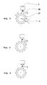
- Fig.2 simplified illustrated locking unit, has the already mentioned pawl 38, the sprocket 37, and the electric actuator 7.
- the arrow represents the direction of rotation of the rotor 10, which causes an increase of the clamping force.
- the pawl 38 is not actuated and thus the rotor 10 is not locked.
- the pawl 38 actuated by the coil 40 is momentarily energized to move the permanent magnet 39. It is possible that the pawl 38 just meets a tooth of the ring gear 37, as in Figure 3 is shown.
- the rotor 10 is not locked in this state and will turn back by the so-called activation rotation angle opposite to the direction of rotation, which would cause an increase of the application force (arrow) until the pawl 38 has reached a locking position ( Figure 4 ).
- the invention proposes that the rotor 10 after setting the required for a parking brake application force before actuation of the pawl 38 is rotated by a certain angle in that direction, which corresponds to an increase in the application force.
- the angular position of the rotor 10 is determined by the aforementioned position detection system 46 and the angular amount for further rotation of the rotor corresponds to the pitch angle ⁇ of the ring gear 37, which depends on the number of teeth of the ring gear 37.
- the pawl 38 reaches the next locking position in the direction of rotation, which causes an increase in the application force. This measure ensures that the rotor 10 is locked in a state in which the application force is at least as great as the set application force.
- the angle amount for further rotation of the rotor 10 prior to the actuation of the pawl 38 can also be determined from an additional application force amount. This is before everything makes sense and necessary if no sensor for detecting the angular position of the rotor 10 is provided.
- the rotor 10 is further rotated until the additional application force amount is set.
- This additional application force amount is chosen such that it is ensured that the pawl 38 reaches the next locking position in that direction of rotation, which causes an increase in the application force.
- the additional application force amount may be determined by a safety amount. This amount of safety takes into account the estimated or experimentally determined temperatures and thermal expansions in the disc brake as well as the stiffness of the caliper and the actuator unit, as a result of which any loss of clamping force when cooling the brake has no safety-relevant consequence.
- Another alternative according to the invention for determining the angular amount by which the rotor 10 is further rotated is the detection of the locking positions of the rotor 10.
- the position detection system 46 determines the angular position of the rotor 10 when the pawl 38 has reached a locking position.
- the angular positions of the locking positions are stored in an electronic storage medium, which may be located in the electronic control unit of the disc brake.
- the angular amount for further rotation of the rotor 10 after setting the required application force is then obtained from the comparison of the current angular position of the rotor 10 and the knowledge of the angular position of the next in the application direction locking position. By these measures, the required application force for a parking brake operation is maintained.
Landscapes
- Engineering & Computer Science (AREA)
- General Engineering & Computer Science (AREA)
- Mechanical Engineering (AREA)
- Braking Arrangements (AREA)
Description
Die Erfindung betrifft ein Verfahren zum Betrieb einer elektromechanisch betätigbaren Scheibenbremse für Kraftfahrzeuge mit einer Feststellbremsvorrichtung und einer Betätigungseinheit, die zur Erzeugung einer Bremskraft eine elektromechanische Antriebseinheit aufweist, von der mindestens ein mechanisch-rotatorisches Element durch eine Verriegelungseinheit mit einem Verriegelungselement verriegelbar ist, sowie mit einem Spannkraftsensor oder einem Sensor zur Erkennung der Winkelstellung des mechanisch-rotatorischen Elements.The invention relates to a method for operating an electromechanically actuated disc brake for motor vehicles with a parking brake device and an actuating unit which has an electromechanical drive unit for generating a braking force, of which at least one mechanical-rotary element can be locked by a locking unit with a locking element, and with a Clamping force sensor or a sensor for detecting the angular position of the mechanical-rotary element.
Eine derartige elektromechanisch betätigbare Scheibenbremse ist aus der
Als weniger vorteilhaft ist beim Betrieb der vorbekannten Scheibenbremse anzusehen, dass die zur Verriegelung des Rotors betätigte Sperrklinke nicht in jeder Winkelstellung des Rotors eine sofortige Verriegelung/Blockierung bewirkt. Der Rotor dreht sich um einen sogenannten Aktivierungswinkel entgegen der Richtung, die eine Erhöhung der Zuspannkraft entsprechen würde, zurück bis die Sperrklinke die Verriegelungsposition erreicht hat. Dies hat jedoch zur Folge, dass die eingestellte Zuspannkraft verringert wird, was als nachteilig angesehen wird.As less advantageous in the operation of the known disc brake is considered that the actuated to lock the rotor pawl does not cause an immediate locking / blocking in each angular position of the rotor. The rotor rotates back through a so-called activation angle counter to the direction that would correspond to an increase in the application force until the pawl reaches the lock position has reached. However, this has the consequence that the set clamping force is reduced, which is considered disadvantageous.
Es ist daher Aufgabe der vorliegenden Erfindung, eine elektromechanisch betätigbare Scheibenbremse der eingangs genannten Gattung derart zu betreiben, dass eine Verringerung der für einen Feststellbremsvorgang eingestellten Zuspannkraft vermieden wird.It is therefore an object of the present invention to operate an electromechanically operable disc brake of the type mentioned in such a way that a reduction of the set for a parking brake application force is avoided.
Diese Aufgabe wird erfindungsgemäß dadurch gelöst, dass das mechanisch-rotatorische Element nach Einstellung der für einen Feststellbremsvorgang erforderlichen Zuspannkraft vor der Betätigung des Verriegelungselementes um einen bestimmten Winkelbetrag in diejenige Richtung weiter gedreht wird, die einer Erhöhnung der Zuspannkraft entspricht.This object is achieved in that the mechanical-rotary element is rotated by setting the required for a parking brake application force before actuation of the locking element by a certain angle in that direction, which corresponds to an increase in the application force.
Zur Konkretisierung des Erfindungsgedankens ist vorgesehen, dass die Verriegelungseinheit durch eine Sperrklinke und ein Zahnrad gebildet wird, dessen Teilungswinkel den Winkelbetrag bestimmt.To concretize the inventive concept, it is provided that the locking unit is formed by a pawl and a gear whose pitch angle determines the angular amount.
Bei einer vorteilhaften Ausgestaltung des Erfindungsgegenstandes wird der Winkelbetrag aus einem zusätzlichen Zuspannkraftbetrag bestimmt, der durch die Anzahl der Verriegelungspositionen der Verriegelungseinheit und aus einem Sicherheitsbetrag bestimmt wird. Dabei ist vorgesehen, dass der Sicherheitsbetrag mit Hilfe der Steifigkeit des Bremssattels und der Betätigungseinheit, sowie mit der ermittelten oder geschätzten Temperatur der Scheibenbremse bestimmt wird.In an advantageous embodiment of the subject invention, the angular amount of an additional Zuspannkraftbetrag is determined, which is determined by the number of locking positions of the locking unit and a security amount. It is provided that the amount of security is determined by means of the stiffness of the caliper and the actuating unit, and with the determined or estimated temperature of the disc brake.
Bei einer weiteren vorteilhaften Ausgestaltung des Erfindungsgegenstandes werden die Verriegelungspositionen der Verriegelungseinheit mit Hilfe des Sensors zur Erkennung der Winkelstellung des mechanisch-rotatorischen Elements ermittelt und in einem elektronischen Speichermedium gespeichert werden und der Winkelbetrag zum Weiterdrehen des mechanisch-rotatorischen Elements aus dem Vergleich der aktuellen Winkelstellung des mechanisch-rotatorischen Elements und der gespeicherten Verriegelungspositionen bestimmt.In a further advantageous embodiment of the subject invention, the locking positions of Locking unit determined by means of the sensor for detecting the angular position of the mechanical-rotatory element and stored in an electronic storage medium and the angular amount for further rotation of the mechanical-rotary element from the comparison of the current angular position of the mechanical-rotary element and the stored locking positions determined.
Die Erfindung wird in der nachfolgenden Beschreibung eines Ausführungsbeispiels unter Bezugnahme auf die beiliegenden Zeichnungen näher erläutert. In der Zeichnung zeigt:
- Fig. 1
- eine Ausführung einer elektromechanisch betätigbaren Scheibenbremse im Axialschnitt, an der das erfindungsgemäße Verfahren durchgeführt werden kann,
- Fig. 2
- eine schematische Darstellung einer Verriegelungseinheit, die aus einem Zahnrad und einer Sperrklinke gebildet ist, im nicht verriegelten Zustand,
- Fig. 3
- eine schematische Darstellung einer Verriegelungseinheit mit betätigter Sperrklinke und
- Fig.4
- eine schematische Darstellung einer Verriegelungseinheit im verriegelten Zustand.
- Fig. 1
- an embodiment of an electromechanically actuated disc brake in axial section at which the method according to the invention can be carried out,
- Fig. 2
- a schematic representation of a locking unit, which is formed of a gear and a pawl, in the unlocked state,
- Fig. 3
- a schematic representation of a locking unit with actuated pawl and
- Figure 4
- a schematic representation of a locking unit in the locked state.
Die in der Zeichnung dargestellte, elektromechanisch betätigbare Scheibenbremse, an der das erfindungsgemäße Verfahren durchgeführt werden kann, wird aus einer Betätigungseinheit und einem lediglich schematisch angedeutetem Bremssattel, der in einem nicht gezeigten feststehenden Halter verschiebbar gelagert ist, gebildet. Ein Paar von Reibbelägen 4 und 5 ist im Bremssattel derart angeordnet, dass sie der linken und der rechten Seitenfläche einer Bremsscheibe 6 zugewandt sind.The illustrated in the drawing, electromechanically actuated disc brake on which the inventive method can be performed, is formed of an actuating unit and a merely schematically indicated caliper which is slidably mounted in a stationary holder, not shown. A pair of
Nachstehend wird der in der Zeichnung rechts gezeigte Reibbelag 4 als erster Reibbelag und der andere, mit 5 bezeichnete Reibbelag als zweiter Reibbelag bezeichnet.Hereinafter, the friction lining 4 shown on the right in the drawing as the first friction lining and the other, designated 5 friction lining referred to as the second friction lining.
Während der erste Reibbelag 4 mittels eines Betätigungselements 15 durch die Betätigungseinheit direkt mit der Bremsscheibe 6 in Eingriff bringbar ist, wird der zweite Reibbelag 5 durch die Wirkung einer bei der Betätigung der Anordnung vom Bremssattel aufgebrachten Reaktionskraft gegen die gegenüberliegende Seitenfläche der Bremsscheibe 6 gedrückt.While the first friction lining 4 can be brought directly into engagement with the
Die Betätigungseinheit, die mittels nicht gezeigter Befestigungsmittel am Bremssattel angebracht ist, weist einen modularen Aufbau auf und besteht im wesentlichen aus drei selbständig handhabbaren Baugruppen bzw. Modulen, und zwar aus einer elektromechanischen Antriebseinheit 1, einem den ersten Reibbelag 4 betätigenden ersten Untersetzungsgetriebe 2 und einem zwischen der elektromechanischen Antriebseinheit 1 und dem ersten Untersetzungsgetriebe 2 wirkungsmäßig geschalteten zweiten Untersetzungsgetriebe 3.The actuating unit, which is attached by means not shown fastening means on the brake caliper, has a modular structure and consists essentially of three independently manageable modules or modules, namely an electromechanical drive unit 1, a first friction lining 4 actuated first reduction gear 2 and a between the electromechanical drive unit 1 and the first reduction gear 2 operatively connected second reduction gear 3rd
Die vorhin erwähnte elektromechanische Antriebseinheit 1 besteht aus einem Elektromotor 11, der im dargestellten Beispiel als ein permanentmagneterregter, elektronisch kommutierter Motor ausgebildet ist, dessen Stator 9 unbeweglich in einem Motorgehäuse 12 angeordnet ist und dessen Rotor 10 durch einen ringförmigen Träger 13 gebildet ist, der mehrere Permanentmagnetsegmente 14 trägt. Zwischen dem Torque-Motor 11 und dem vorhin erwähnten Betätigungselement 15 ist wirkungsmäßig das erste Untersetzungsgetriebe 2 angeordnet, das als ein Kugelgewindetrieb 16 bis 18 ausgebildet ist, das in einem Getriebegehäuse 19 gelagert ist. Der Kugelgewindetrieb besteht dabei aus einer Gewindemutter 16 sowie einer Gewindespindel 17, wobei zwischen der Gewindemutter 16 und der Gewindespindel 17 mehrere Kugeln 18 angeordnet sind, die bei einer Rotationsbewegung der Gewindemutter 16 umlaufen und die Gewindespindel 17 in eine axiale bzw. translatorische Bewegung versetzen.The above-mentioned electromechanical drive unit 1 consists of an
Die Anordnung ist dabei derart getroffen, dass der Rotor 10 des Motors 11 unter Zwischenschaltung des zweiten Untersetzungsgetriebes 3 die Gewindemutter 16 antreibt, während die Gewindespindel 17 mittels einer Druckstange 24 mit dem vorhin erwähnten Betätigungselement 15 zusammenwirkt, das vorzugsweise durch eine Kraftübertragungsplatte gebildet ist, die sich am ersten Reibbelag 4 abstützt. Die Druckstange 24, die von einer in der Gewindespindel 17 ausgebildeten, konischen Bohrung 25 aufgenommen wird, stützt sich verdrehgesichert einerseits mittels eines Mehrkants 28 in einem axialen Fortsatz 26 der Kraftübertragungsplatte 15 und andererseits am Boden der Bohrung 25 ab. Um die im Betrieb der Betätigungseinheit auftretenden Querkräfte in das Getriebegehäuse 19 einzuleiten ist die Kraftübertragungsplatte 15 mit zwei radial gegenüberliegenden Führungsbolzen 20 versehen, die in im Getriebegehäuse 19 ausgebildeten Führungsflächen bzw. Bohrungen 21 geführt sind. Der Lagerung der Gewindemutter 16 im Getriebegehäuse 19 dient ein Axiallager bzw. Kugellager, das aus einem an der Gewindemutter 16 ausgeformten radialen Kragen 29, mehreren, nicht näher bezeichneten Kugeln sowie einem Lagerring 22 besteht. Zwischen dem Lagerring 22 und einer im Getriebegehäuse 19 ausgebildeten ringförmigen Abstützfläche ist ein Spannkraftsensor 23 angeordnet, der der Ermittlung der von der Betätigungseinheit aufgebrachten Spannkraft dient.The arrangement is made such that the
Um die Funktion einer Feststellbremse realisieren zu können weist die Betätigungseinheit elektromechanische Mittel auf, die, mit dem Rotor 10 des Elektromotors 11 zusammenwirkend, sein Verriegeln ermöglichen. Im in
Die in
Zum Einleiten eines Feststellbremsvorgangs wird die Sperrklinke 38 betätigt, indem die Spule 40 kurzzeitig bestromt wird um den Permanentmagneten 39 zu bewegen. Dabei ist es möglich, dass die Sperrklinke 38 gerade auf einen Zahn des Zahnkranzes 37 trifft, wie es in
Das Zurückdrehen des Rotors 10 um den Betrag des Aktivierungswinkels, entgegen der Richtung, die eine Erhöhung der Zuspannkraft bewirken würde, hat einen unerwünschten Verlust der Zuspannkraft zur Folge. Deshalb wird erfindungsgemäß vorgeschlagen, dass der Rotor 10 nach Einstellung der für einen Feststellbremsvorgang erforderlichen Zuspannkraft vor der Betätigung der Sperrklinke 38 um einen bestimmten Winkelbetrag in diejenige Richtung weiter gedreht wird, die einer Erhöhnung der Zuspannkraft entspricht. Dabei wird die Winkelstellung des Rotors 10 vom bereits erwähnten Lageerkennungssystems 46 bestimmt und der Winkelbetrag zum Weiterdrehen des Rotors entspricht dem Teilungswinkel α des Zahnkranzes 37, der von der Anzahl der Zähne des Zahnkranzes 37 abhängt. Dadurch erreicht die Sperrklinke 38 die nächste Verriegelungsposition in derjenigen Drehrichtung, die eine Erhöhung der Zuspannkraft bewirkt. Durch diese Maßnahme wird gewährleistet, dass der Rotor 10 in einem Zustand verriegelt wird, bei dem die Zuspannkraft mindestens gleich groß, wie die eingestellte Zuspannkraft ist.The turning back of the
Alternativ kann der Winkelbetrag zum Weiterdrehen des Rotors 10 vor der Betätigung der Sperrklinke 38 auch aus einem zusätzlichen Zuspannkraftbetrag bestimmt werden. Dies ist vor allem dann sinnvoll und erforderlich, wenn kein Sensor zur Erkennung der Winkelstellung des Rotors 10 vorgesehen ist. Nach der Einstellung der erforderlichen Zuspannkraft, die vom Spannkraftsensor 23 ermittelt wird, wird der Rotor 10 weitergedreht, bis der zusätzliche Zuspannkraftbetrag eingestellt ist. Dieser zusätzliche Zuspannkraftbetrag wird dabei derart gewählt, dass gewährleistet ist, dass die Sperrklinke 38 die nächste Verriegelungsposition in derjenigen Drehrichtung, die eine Erhöhung der Zuspannkraft bewirkt, erreicht. Zudem kann der zusätzliche Zuspannkraftbetrag durch einen Sicherheitsbetrag bestimmt werden. Dieser Sicherheitsbetrag berücksichtigt die geschätzten oder experimentell ermittelten Temperaturen und Temperaturdehnungen in der Scheibenbremse sowie die Steifigkeit des Bremssattels und der Betätigungseinheit, wodurch eventuell auftretende Spannkraftverluste beim Abkühlen der Bremse keine sicherheitsrelevante Folge hat.Alternatively, the angle amount for further rotation of the
Eine weitere erfindungsgemäße Alternative für die Bestimmung des Winkelbetrags um den der Rotor 10 weitergedreht wird, ist die Erfassung der Verriegelungspositionen des Rotors 10. Dabei ermittelt das Lageerkennungssystem 46 die Winkelstellung des Rotors 10, wenn die Sperrklinke 38 eine Verriegelungsposition erreicht hat. Die Winkelstellungen der Verriegelungspositionen werden in einem elektronischen Speichermedium gespeichert, das sich in der elektronischen Steuer- und Regeleinheit der Scheibenbremse befinden kann. Der Winkelbetrag zum Weiterdrehen des Rotors 10 nach Einstellung der erforderlichen Zuspannkraft ergibt sich dann aus dem Vergleich der aktuellen Winkelstellung des Rotors 10 und der Kenntnis der Winkelstellung der nächsten in Zuspannrichtung gelegenen Verriegelungsposition. Durch diese Maßnahmen bleibt die erforderliche Zuspannkraft für einen Feststellbremsvorgang erhalten.Another alternative according to the invention for determining the angular amount by which the
Claims (5)
- Method of operating an electromechanically operable disc brake for motor vehicles with a parking brake device and an actuating unit, which includes an electromechanical driving unit (1) for generating a brake force, with at least one mechanical-rotational element (37) of said device being lockable by a locking unit with a locking element (38), as well as with a tension force sensor or a sensor for detecting the angular position of the mechanical-rotational element,
characterized in that after the adjustment of the clamping force required for a parking brake operation, prior to the actuation of the locking element (38), the mechanical-rotational element (37) is rotated further by a defined angular amount in that direction which corresponds to an increase of the clamping force. - Method as claimed in claim 1,
characterized in that the locking unit is formed of a detent pawl (38) and a toothed wheel (37) whose angular pitch determines the angular amount. - Method as claimed in claim 1,
characterized in that the angular amount is determined from an additional amount of clamping force which is determined by the number of the locking positions of the locking unit and from a safety value. - Method as claimed in claim 1,
characterized in that the locking positions of the locking unit are found out using the sensor for the detection of the angular position of the mechanical-rotational element and are saved in an electronic memory medium, and the angular amount for continued rotation of the mechanical-rotational element is determined from the comparison between the current angular position of the mechanical-rotational element and the memorized locking positions. - Method as claimed in claim 3,
characterized in that the safety value is determined by way of the rigidity of the brake caliper and the actuating unit as well as with the determined or estimated temperature of the disc brake.
Applications Claiming Priority (4)
| Application Number | Priority Date | Filing Date | Title |
|---|---|---|---|
| DE10311750 | 2003-03-18 | ||
| DE10311750 | 2003-03-18 | ||
| DE10325414A DE10325414A1 (en) | 2003-03-18 | 2003-06-05 | Method for operating an electromechanically actuated disc brake |
| DE10325414 | 2003-06-05 |
Publications (2)
| Publication Number | Publication Date |
|---|---|
| EP1460300A1 EP1460300A1 (en) | 2004-09-22 |
| EP1460300B1 true EP1460300B1 (en) | 2008-08-20 |
Family
ID=32826215
Family Applications (1)
| Application Number | Title | Priority Date | Filing Date |
|---|---|---|---|
| EP20040101130 Expired - Lifetime EP1460300B1 (en) | 2003-03-18 | 2004-03-18 | Method of operation for parking brakes used with electromechanically actuated disc brakes. |
Country Status (1)
| Country | Link |
|---|---|
| EP (1) | EP1460300B1 (en) |
Cited By (1)
| Publication number | Priority date | Publication date | Assignee | Title |
|---|---|---|---|---|
| DE102020213916A1 (en) | 2020-02-14 | 2021-08-19 | Continental Teves Ag & Co. Ohg | Electromechanical brake actuator with integrated EPB parking brake module (monostable rotating armature magnet) |
Families Citing this family (4)
| Publication number | Priority date | Publication date | Assignee | Title |
|---|---|---|---|---|
| KR101870635B1 (en) * | 2011-10-24 | 2018-06-26 | 현대모비스 주식회사 | Brake apparatus for vehicle |
| EP3663149B1 (en) * | 2018-12-06 | 2023-03-29 | IMS Gear SE & Co. KGaA | Locking device for an electromechanical brake of motor vehicle brake, electromechanical brake provided with such a locking device and motor vehicle equipped with such an electromechanical brake |
| DE102021209379B3 (en) * | 2021-08-26 | 2023-01-26 | Continental Automotive Technologies GmbH | Method of operating a locking plunger, actuator and vehicle brake |
| CN117698673B (en) * | 2024-02-06 | 2024-04-12 | 北京航空航天大学 | Electronic mechanical braking system of electric automobile |
Family Cites Families (4)
| Publication number | Priority date | Publication date | Assignee | Title |
|---|---|---|---|---|
| US6003640A (en) * | 1997-05-09 | 1999-12-21 | The B.F. Goodrich Company | Electronic braking system with brake wear measurement and running clearance adjustment |
| DE19807328C2 (en) * | 1998-02-20 | 2003-08-28 | Lucas Ind Plc | Electromechanically actuated disc brake |
| GB9823203D0 (en) * | 1998-10-24 | 1998-12-16 | Lucas Ind Plc | Parking-braking in vehicles |
| DE10054471A1 (en) * | 2000-11-03 | 2002-05-16 | Siemens Ag | Electromechanically actuated disc brake with a parking brake system |
-
2004
- 2004-03-18 EP EP20040101130 patent/EP1460300B1/en not_active Expired - Lifetime
Cited By (1)
| Publication number | Priority date | Publication date | Assignee | Title |
|---|---|---|---|---|
| DE102020213916A1 (en) | 2020-02-14 | 2021-08-19 | Continental Teves Ag & Co. Ohg | Electromechanical brake actuator with integrated EPB parking brake module (monostable rotating armature magnet) |
Also Published As
| Publication number | Publication date |
|---|---|
| EP1460300A1 (en) | 2004-09-22 |
Similar Documents
| Publication | Publication Date | Title |
|---|---|---|
| EP1032773B1 (en) | Electromechanically actuated disc brake | |
| DE102009039271B4 (en) | Electric disc brake | |
| EP1530528B1 (en) | Method for actuating an electromechanical parking brake device | |
| EP2195218B1 (en) | Ball screw for a motor vehicle brake and motor vehicle brake | |
| DE19628804B4 (en) | Electromechanically actuated disc brake | |
| DE102007053922B4 (en) | Electronic single-motor wedge brake system for locking the parking force | |
| EP1025372B1 (en) | Braking arrangement for a land vehicle | |
| DE10333092A1 (en) | Rotary actuator used in e.g. parking switching apparatus of motor vehicle, has retarder whose input shaft is interlocked with rotor shaft of synchronous motor, to constitute common shaft inside main housing | |
| EP2041446B1 (en) | Positive-fit freewheel mechanism that can be electromechanically actuated, electromechanical brake with a freewheel mechanism of this type for a motor vehicle and method for adjusting the play in a brake of this type | |
| DE19621533A1 (en) | Electromotive brake device | |
| EP1218646A1 (en) | Actuating unit for an electromechanically actuated disc brake | |
| EP0865977A1 (en) | Disc brake being actuated by an electric motor | |
| EP3862235B1 (en) | Parking brake locking device and parking brake | |
| WO2002021010A2 (en) | Operating device for an electromechanically actuated disk brake | |
| DE112019005759T5 (en) | ELECTROMECHANICAL ACTUATOR PACKAGE FOR OPERATING A BRAKE ARRANGEMENT | |
| EP1015786A1 (en) | Electromechanically operated disk brake | |
| WO2020207925A1 (en) | Braking system for a vehicle | |
| DE10015263C2 (en) | Electromechanical braking device, in particular for a motor vehicle | |
| WO2001021975A1 (en) | Actuating unit for an electromechanically actuated disc brake | |
| DE102022130191A1 (en) | Actuator assembly for a vehicle brake and method for actuating an actuator assembly for a vehicle brake | |
| EP1460300B1 (en) | Method of operation for parking brakes used with electromechanically actuated disc brakes. | |
| DE10224688A1 (en) | Stationary brake operating method for automobile electromechanical braking system, uses movement sensor for preventing operation of stationary brake during movement of automobile | |
| EP1460301A2 (en) | Elektromechanically actuated disc brake | |
| EP1141574B1 (en) | Electromechanical brake system for motor vehicles | |
| DE19843123A1 (en) | Electric brake for motor vehicles has blocking brake function produced by pronounced stator and rotor poles and applying defined blocking current to bring poles into latching position |
Legal Events
| Date | Code | Title | Description |
|---|---|---|---|
| PUAI | Public reference made under article 153(3) epc to a published international application that has entered the european phase |
Free format text: ORIGINAL CODE: 0009012 |
|
| AK | Designated contracting states |
Kind code of ref document: A1 Designated state(s): AT BE BG CH CY CZ DE DK EE ES FI FR GB GR HU IE IT LI LU MC NL PL PT RO SE SI SK TR |
|
| AX | Request for extension of the european patent |
Extension state: AL LT LV MK |
|
| 17P | Request for examination filed |
Effective date: 20041027 |
|
| AKX | Designation fees paid |
Designated state(s): DE FR IT |
|
| GRAP | Despatch of communication of intention to grant a patent |
Free format text: ORIGINAL CODE: EPIDOSNIGR1 |
|
| RIN1 | Information on inventor provided before grant (corrected) |
Inventor name: MARON, CHRISTOF, DR. Inventor name: LINHOFF, PAUL Inventor name: DRUMM, STEFAN A |
|
| GRAS | Grant fee paid |
Free format text: ORIGINAL CODE: EPIDOSNIGR3 |
|
| GRAA | (expected) grant |
Free format text: ORIGINAL CODE: 0009210 |
|
| AK | Designated contracting states |
Kind code of ref document: B1 Designated state(s): DE FR IT |
|
| REF | Corresponds to: |
Ref document number: 502004007868 Country of ref document: DE Date of ref document: 20081002 Kind code of ref document: P |
|
| PLBE | No opposition filed within time limit |
Free format text: ORIGINAL CODE: 0009261 |
|
| STAA | Information on the status of an ep patent application or granted ep patent |
Free format text: STATUS: NO OPPOSITION FILED WITHIN TIME LIMIT |
|
| 26N | No opposition filed |
Effective date: 20090525 |
|
| PGFP | Annual fee paid to national office [announced via postgrant information from national office to epo] |
Ref country code: IT Payment date: 20120322 Year of fee payment: 9 |
|
| PG25 | Lapsed in a contracting state [announced via postgrant information from national office to epo] |
Ref country code: IT Free format text: LAPSE BECAUSE OF NON-PAYMENT OF DUE FEES Effective date: 20130318 |
|
| REG | Reference to a national code |
Ref country code: FR Ref legal event code: PLFP Year of fee payment: 13 |
|
| REG | Reference to a national code |
Ref country code: FR Ref legal event code: PLFP Year of fee payment: 14 |
|
| REG | Reference to a national code |
Ref country code: FR Ref legal event code: PLFP Year of fee payment: 15 |
|
| PGFP | Annual fee paid to national office [announced via postgrant information from national office to epo] |
Ref country code: PL Payment date: 20190208 Year of fee payment: 16 |
|
| REG | Reference to a national code |
Ref country code: DE Ref legal event code: R084 Ref document number: 502004007868 Country of ref document: DE |
|
| PG25 | Lapsed in a contracting state [announced via postgrant information from national office to epo] |
Ref country code: FR Free format text: LAPSE BECAUSE OF NON-PAYMENT OF DUE FEES Effective date: 20200331 |
|
| PGFP | Annual fee paid to national office [announced via postgrant information from national office to epo] |
Ref country code: DE Payment date: 20210331 Year of fee payment: 18 |
|
| REG | Reference to a national code |
Ref country code: DE Ref legal event code: R081 Ref document number: 502004007868 Country of ref document: DE Owner name: CONTINENTAL AUTOMOTIVE TECHNOLOGIES GMBH, DE Free format text: FORMER OWNER: CONTINENTAL TEVES AG & CO. OHG, 60488 FRANKFURT, DE |
|
| REG | Reference to a national code |
Ref country code: DE Ref legal event code: R119 Ref document number: 502004007868 Country of ref document: DE |
|
| PG25 | Lapsed in a contracting state [announced via postgrant information from national office to epo] |
Ref country code: DE Free format text: LAPSE BECAUSE OF NON-PAYMENT OF DUE FEES Effective date: 20221001 |