EP1460182A1 - Travelling device with parking brake - Google Patents
Travelling device with parking brake Download PDFInfo
- Publication number
- EP1460182A1 EP1460182A1 EP04015222A EP04015222A EP1460182A1 EP 1460182 A1 EP1460182 A1 EP 1460182A1 EP 04015222 A EP04015222 A EP 04015222A EP 04015222 A EP04015222 A EP 04015222A EP 1460182 A1 EP1460182 A1 EP 1460182A1
- Authority
- EP
- European Patent Office
- Prior art keywords
- brake
- parking
- disc
- header
- main frame
- Prior art date
- Legal status (The legal status is an assumption and is not a legal conclusion. Google has not performed a legal analysis and makes no representation as to the accuracy of the status listed.)
- Granted
Links
Images









Classifications
-
- B—PERFORMING OPERATIONS; TRANSPORTING
- B62—LAND VEHICLES FOR TRAVELLING OTHERWISE THAN ON RAILS
- B62D—MOTOR VEHICLES; TRAILERS
- B62D51/00—Motor vehicles characterised by the driver not being seated
- B62D51/04—Motor vehicles characterised by the driver not being seated the driver walking
-
- B—PERFORMING OPERATIONS; TRANSPORTING
- B62—LAND VEHICLES FOR TRAVELLING OTHERWISE THAN ON RAILS
- B62D—MOTOR VEHICLES; TRAILERS
- B62D49/00—Tractors
- B62D49/04—Tractors modified to take pushing devices
-
- B—PERFORMING OPERATIONS; TRANSPORTING
- B62—LAND VEHICLES FOR TRAVELLING OTHERWISE THAN ON RAILS
- B62D—MOTOR VEHICLES; TRAILERS
- B62D55/00—Endless track vehicles
- B62D55/08—Endless track units; Parts thereof
- B62D55/104—Suspension devices for wheels, rollers, bogies or frames
- B62D55/116—Attitude or position control of chassis by action on suspension, e.g. to compensate for a slope
-
- E—FIXED CONSTRUCTIONS
- E01—CONSTRUCTION OF ROADS, RAILWAYS, OR BRIDGES
- E01H—STREET CLEANING; CLEANING OF PERMANENT WAYS; CLEANING BEACHES; DISPERSING OR PREVENTING FOG IN GENERAL CLEANING STREET OR RAILWAY FURNITURE OR TUNNEL WALLS
- E01H5/00—Removing snow or ice from roads or like surfaces; Grading or roughening snow or ice
- E01H5/04—Apparatus propelled by animal or engine power; Apparatus propelled by hand with driven dislodging or conveying levelling elements, conveying pneumatically for the dislodged material
-
- E—FIXED CONSTRUCTIONS
- E01—CONSTRUCTION OF ROADS, RAILWAYS, OR BRIDGES
- E01H—STREET CLEANING; CLEANING OF PERMANENT WAYS; CLEANING BEACHES; DISPERSING OR PREVENTING FOG IN GENERAL CLEANING STREET OR RAILWAY FURNITURE OR TUNNEL WALLS
- E01H5/00—Removing snow or ice from roads or like surfaces; Grading or roughening snow or ice
- E01H5/04—Apparatus propelled by animal or engine power; Apparatus propelled by hand with driven dislodging or conveying levelling elements, conveying pneumatically for the dislodged material
- E01H5/08—Apparatus propelled by animal or engine power; Apparatus propelled by hand with driven dislodging or conveying levelling elements, conveying pneumatically for the dislodged material dislodging essentially by driven elements
- E01H5/09—Apparatus propelled by animal or engine power; Apparatus propelled by hand with driven dislodging or conveying levelling elements, conveying pneumatically for the dislodged material dislodging essentially by driven elements the elements being rotary or moving along a closed circular path, e.g. rotary cutter, digging wheels
- E01H5/098—Apparatus propelled by animal or engine power; Apparatus propelled by hand with driven dislodging or conveying levelling elements, conveying pneumatically for the dislodged material dislodging essentially by driven elements the elements being rotary or moving along a closed circular path, e.g. rotary cutter, digging wheels about horizontal or substantially horizontal axises perpendicular or substantially perpendicular to the direction of clearing
Definitions
- the present invention relates to a travelling device with a parking brake.
- the travelling device can be for example a snow remover.
- a snow remover is provided with a header, whose vertical position can be adjusted in relative to the snow surface, so as to enable snow-removing whether the snow lies deep or shallow.
- a large-sized snow remover uses an actuator driven by an engine or a motor, or a screwing means with a handle.
- a small-sized snow remover uses a lever or a pedal, which is provided on a rear portion thereof, thereby saving power and costs and securing the compactness thereof.
- the conventional small-sized snow remover is liable to fall into an error in the vertical positioning of the header thereof because the position for an operator behind the snow remover is inconvenient for seeing the header and the vertical position of the header is controlled at steps. If the header is excessively lowered, the ground surface is damaged by a plowing auger in the header. If it is insufficiently lowered, the snow remains much after snow-removing.
- the header of the snow remover is placed on the snow surface only with its empty weight. If the weight is light, the header may unexpectedly rise above the snow surface, thereby reducing the snow-removing efficiency.
- An object of the invention is to provide a travelling device, for example a snow remover, with a parking brake which can be easily mounted and maintained.
- the parking brake of the travelling device of the invention comprises a braked device provided on an axle supporting a travelling wheel and a braking device provided on a main frame.
- the braked device includes a disc having a plurality of recesses on the periphery thereof
- the braking device includes a brake arm rotatably provided on said main frame, an operating lever mounted on a first end portion of said brake arm, and an engaging member provided on a second end portion of said brake arm, and said disc is provided so as to rotate together with said travelling wheel and so as to be braked when said brake arm is rotated to engage said engaging member into one of said recesses of said disc.
- Fig. 1 is a perspective left side view of a snow remover according to the present invention
- Fig. 2 is a perspective rear view of a lower portion of a header 1 of the snow remover showing sledges 8 attached onto a plowing-auger cover 48;
- Fig. 3 is a perspective rear view of the snow remover
- Fig. 4 is a perspective right side view of a rear portion of a main frame 9 of the snow remover showing a locking link mechanism for locking or releasing main frame 9 and header 1 with and from a traveling device 50;
- Fig. 5 is a perspective left side view of the same
- Fig. 6 is a perspective left side view of the snow remover shown in Fig. 1, wherein header 1 locked with travel device 50 falls onto the snow surface before traveling device 50 is released from main frame 9 to be placed on the snow surface.
- Fig. 7 is a perspective view of a mechanism for rotating a chute 47 including a motor 55 and a chute flange 49 provided on a blower cover 46 of header 1;
- Fig. 8 is a rear view of motor 55 removed from the snow remover
- Fig. 9(a) is a perspective rear view of a battery 26 mounted on a rear portion of main frame 9 when a battery cover 65 is removed
- Fig. 9(b) is a perspective rear view of the same when battery cover 65 is attached;
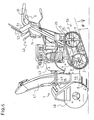
- Fig. 10 is a perspective left side view of the snow remover provided with a parking brake 70;
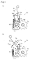
- Fig. 11(a) is a left side view of parking brake 70 when a parking lever rod 78 is located at a parking position
- Fig. 11(b) is a left side view of the same when parking lever rod 78 is located at a release position;
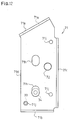
- Fig. 12 is a left side view of a brake base plate 71;
- Fig. 13 is a plan view of the same
- Fig. 14 is a bottom view of the same
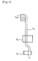
- Fig. 15 is a left side view of a brake arm plate 74 of parking brake 70;
- Fig. 16 is a rear view of the same
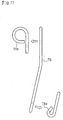
- Fig. 17 is a front view of a parking lever rod 78
- Fig. 18 is a side view of a brake disc 79
- Fig. 19 is a plan view partly in section of the same.
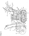
- Fig. 20 is a perspective left side view of the snow remover provided with a parking brake 90;
- Fig. 21(a) is a left side view of parking brake 90 when a parking lever 39 is located at a parking position
- Fig. 21(b) is a left side view of the same when parking lever 39 is located at a release position;
- Fig. 22 is a left side view of a brake arm plate 74 of parking brake 90.
- Fig. 23 is a plan view of parking lever 39.
- a header 1 is disposed in front of a main frame 9.
- Header 1 comprises a blower, a plowing auger and a chute 47.
- the blower is disposed in a blower cover 46 continuously connected to the front end of main frame 9.
- the plowing auger is covered with an auger cover 48 in front of blower cover 46.
- the plowing auger and the blower are synchronously driven.
- the rotating plowing auger crashes the snow on the ground and carries the snow to the middle portion thereof.
- the blower upwardly blows the snow collected at the middle portion of the plowing auger.
- the blown snow is guided by chute 47 and discharged outward in an optional direction.
- Chute 47 is integrally provided at its bottom with a chute flange 49.
- Chute flange 49 is rotatably mounted on the top of a chute base 46a which is upwardly formed of blower cover 46.
- Chute flange 49 is formed with a crown-cap-shaped gear 49a having downward teeth, which is drivingly connected to a motor 55 disposed below chute flange 49.
- the mechanism interposed between motor 55 and a front portion of chute flange 49 is covered with a cover.
- Fig. 1 illustrates the snow remover when the cover is removed therefrom. The mechanism for rotation of chute 47 will be detailed later in accordance with Figs. 7 and 8.
- a pair of sledges 8 are fixedly hung symmetrically disposed at a lower portion of header 1 so as to be put on the ground (snow surface).
- the pair of sledges 8 are fixedly hung from left and right rear bottom portions of auger cover 48.
- sledges 8 may be attached to another part of header 1, e.g., blower cover 46.
- the positions of sledges 8 can be adjusted in a lateral direction of the snow remover at need.
- the vertical positions of sledges 8 can be adjusted for fine adjustment of the bottom end of header 1 in relative to the snow surface.
- rollers may be provided below blower cover 46. The vertical positions of the rollers may be adjusted.
- a pair of left and right handles 10 are extended upwardly backward from the left and right rear ends of main frame 9.
- a control portion 40 is constituted above left and right handles 10. That is, a control box 14 is disposed between the top portions of handles 10.
- a travel clutch lever 51 and a snow-removing clutch lever 52, which are deadman clutch levers, are disposed on respective handles 10.
- a lock lever 6 is vertically rotatably provided on a rear portion of control box 14. As discussed later, lock lever 6 is operated to fix the vertical position of header 1.
- An engine 60 is mounted on main frame 9.
- An output shaft projects forward from engine 60.
- a belt cover 43 is disposed on an upper portion of main frame 9.
- a transmission is disposed in a lower portion of main frame 9.
- a pulley fixed on the output shaft of engine 60 is disposed in belt cover 43 so as to transmit the power of engine 60 to both the transmission and header 1.
- the transmission includes an HST.
- a front axle 4 serving as a travel-driving axle projects from the transmission in both lateral directions so as to penetrate main frame 9. Furthermore, each end of front axle 4 projects outward from a front portion of each of track frames 42 disposed outside respective left and right sides of main frame 9.
- Main frame 9 is pivoted onto front axle 4 so as to be tilted forward and backward.
- a pair of drive sprockets 2 are fixed onto respective outer ends of front axle 4.
- a rear axle 11 is laterally disposed between rear portions of left and right track frames 42.
- a pair of follower sprockets 3 are rotatably provided onto respective outer ends of rear axle 11.
- Drive and follower sprockets 2 and 3 outside each of track frames 42 are bound by a crawler belt 5.
- front and rear axles 4 and 11, left and right sprockets 2 and 3, track frames 42, crawler belts 5 and so on constitute a crawler type traveling device 50.
- a battery base 25 projects backward from the rear end of main frame 9 below handles 10.
- a battery 26 is mounted on baterry base 25 and fixed thereto by a supporter 27 and a battery cover 28. Such a rear mounting of battery 26 balances the snow remover in the longitudinal direction thereof. Otherwise, battery 26 may be disposed in a front, left or right portion of the snow remover. The manner of mounting battery 26 will be detailed later in accordance with Fig. 8 (a) and (b)
- a header 1 integrally joined to main frame 9 and handles 10 can be rotated centering front axle 4 by vertically moving handles 10 so that the vertical position of header 1 can be steplessly adjusted according to the degree of vertical motion of handles 10.
- the whole range of vertical movement of header 1 which is larger than that of sledges 8 can be obtained.
- Each crawler belt 5 contacts with the ground (the snow surface) at a pitch between sprockets 2 and 3.
- the grounding surface of each crawler belt 5 is pressed against the ground by a crawler guide 7 hung from track frame 42.
- the rigidity of grounding crawler belts 5 can be secured so as to prevent the snow remover from being vertically reversed however roughly header 1 may be moved vertically.
- rear axle 11 is rotatably supported between left and right track frames 42.
- a locking arm 13 is pivotally provided onto rear axle 11.
- a fixture plate 15 is extended backward from the rear end of main frame 9.
- Locking arm 13 can be fixed to fixture plate 15 by a bolt 17 and a nut 18. That is, bolt 17 is passed through a slot 13a formed in locking arm 13, fixture plate 15, a retaining plate 21 and nut 18.
- a plain washer 19 is interposed between a head of bolt 17 and locking arm 13.
- any frictional washer may be provided so as to press the head of bolt 17 against locking arm 13, thereby fastening locking arm 13 to fixture plate 15 strongly.
- it may be replaced with a spring washer or a coned disc spring washer.
- Retaining plate 21 is provided with a retaining hole which has a hexagonal shape in correspondence to the shape of nut 18.
- nut 18 screwed around bolt 17 is engaged in the retaining hole of retaining plate 21.
- retaining plate 21 is provided with a slot 21a.
- a bolt 20 is passed through slot 21a of retaining plate 21 and fixture plate 15, and screwed up by a nut so as to fasten retaining plate 21 to fixture plate 15.
- Lock lever 6 which is verticaly rotatably provided on control box 14 as mentioned above, is disposed adjacently to one of handles 10 (in this embodiment, right handle 10) so as to facilitate its operation while handles 10 are held by hands.
- Lock lever 6 can be switched between a lock position and a release position. By rotation of lock lever 6 between the two positions, connecting rod 12 is vertically moved so as to rotate arm 16 centering an axis of bolt 17, whereby bolt 17 is rotated around its axis together with arm 16 so as to change a distance between the head of bolt 17 and the nut 18 retained in retaining plate 21.
- lock lever 6 When lock lever 6 is located at the lock position, the distance is reduced so as to fasten locking arm 13 to fixture plate 15, thereby locking main frame 9 and header 1 with rear axle 11 of traveling device 50.
- lock lever 6 is operated to rotate not nut 18 but bolt 17.
- it may be constructed that lock lever 6 is operated to rotate nut 18 while bolt 17 is retained. All the requirement for locking or releasing locking arm 13 with and from fixture plate 15 is to change the gap between the head of bolt 17 and nut 18 in which fixture plate 15 is. sandwiched.
- lock lever 6 While lock lever 6 is located at the release position, handles 10 held by an operator's hands are vertically moved so as to rotate main frame 9 and header 1 centering front axle 4 while bolt 17 being guided along slot 13a, thereby adjusting the height of header 1.
- lock lever 6 is switched to the lock position so as to fix header 1 at its height.
- this adjusting work can be performed only while bolt 20 is allowed to slide in slot 21a. If the degree of abrasion of locking arm 13 exceeds the limit of that with which such rotation of retaining plate 21 deals, the nut is removed from bolt 20 and retaining plate 21 is removed from nut 18. Then, nut 18 is screwed along bolt 17 so as to fasten locking arm 13 to fixture plate 15 adequately. Finally, retaining plate 21 is engaged with nut 18 and the nut is screwed up on bolt 20 so as to fasten retaining plate 21 to fixture plate 15.
- Header 1 can be rotated centering front axle 4 only while bolt 17 is allowed to slide in slot 13a. Header 1 is constructed so as to be inclined forwardly downward even if it is located at its upper limit height. That is, the center of gravity in the snow remover is constantly located in front of front axle 4 in spite of adjustment of the height of header 1.
- a stay 22 projects backward from a bottom rear end of main frame 9.
- a spring 23 is interposed between stay 22 and a bottom portion of locking arm 13 so as to bias main frame 9 and header 1 toward rear axle 11. Consequently, the front end of header 1 is biased downward by spring 23.
- the resultant downward force as combination of the empty weight of header 1 and the biasing force of spring 23 is applied on header 1 so as to maintain the center of gravity in the snow remover in front of front axle 4 except on extraordinary occasions such that the snow remover ascends an extremely steep slope.
- Spring 23 is a stretched spring. Otherwise, the front end of header 1 may be biased downward by any spring such as a compressed spring, a twisted spring or a plate spring, or an actuator other than springs, e.g., a motor or a cylinder.
- lock lever 6 is rotated to the release position so as to make rear axle 11 of traveling device 50 free from main frame 9 and header 1.
- the rear end of traveling device 50 falls with its empty weight, thereby bringing the entire bottom surface of crawler belts 5 into contact with the snow surface.
- lock lever 6 is returned to the lock position so as to fix traveling device 50 to main frame 9 and header 1, thereby completing the location of header 1 and traveling device 50.
- header 1 is naturally placed on the snow surface adequately before traveling device 50 is placed on the snow surface. Thus, header 1 is safe from error in its location with respect to the snow surface.
- the fixture positions of sledges 8 onto auger cover 48 may be adjusted in a vertical direction. As sledges 8 are lowered, the snow remaining after snow-removing is increased.
- lock lever 6, rear axle 11 and main frame 9 are interlockingly connected with one another by the above-mentioned mechanical linkage.
- an actuator e.g., a hydraulic cylinder
- the hydraulic cylinder is actuated to raise the front end of header 1 and then the front end of header 1 or the rear end of traveling device 50 is dropped with its empty gravity, thereby automatically locating header 1 and traveling device 50 with respect to the snow surface without the operation (of lock lever 6) for locking/releasing header 1 and main frame 9 with and from traveling device 50.
- chute flange 49 formed at the bottom of chute 47 is provided with crown-cap shaped gear 49a having downward teeth.
- motor 55 is disposed on blower cover 46 below a front portion of chute flange 49.
- Motor 55 is connected at its right end with a worm wheel housing 56.
- Motor 55 has a lateral worm which is housed in worm wheel housing 56.
- a worm wheel is housed in worm wheel housing 56 so as to engage with the worm.
- a worm wheel shaft 57 serving as an axis of the worm wheel projests backward from worm wheel housing 56.
- a gear 58 is fixed on a rear end of worm wheel shaft 57 so as to engage with gear 49a of chute flange 49. Therefore, the power of motor 55 is transmitted to gear 49a so as to rotate chute 47.
- worm wheel housing 56 As mentioned above, motor 55, worm wheel housing 56 and a front portion of chute flange 49 are usually covered with a cover. Particularly when the cover is removed or whether the cover is provided or not, worm wheel housing 56 may be subjected to dew condensation which results in that water enters worm wheel housing 56. Thus, as shown in Figs. 7 and 8, worm wheel housing 56 is provided at the bottom portion thereof with a drain port 56a which is downwardly open so as to naturally drain water therefrom.
- each of supporters 27 is formed of a rod which is bent in a J-like shape so as to provide a vertical portion and a longitudinal bottom portion.
- the vertical portion of each of supporters 27 is disposed along a lateral middle portion of each of front and rear surfaces of battery 26 mounted on battery base 25.
- the longitudinal bottom portion of supporter 27 is disposed along the bottom surface of battery base 25.
- a sectionally U-like recessed cap plate 64 is put on the top of battery 26.
- the front and rear horizontal surfaces of cap plate 64 are formed at their lateral middle portions with respective bosses 64a.
- the top ends of supporters 27 are passed upward through respective bosses 64a of cap plate 64.
- Battery cables are connected to terminals of battery 26.
- battery cover 28 having a pair of holes is disposed on the top of cap plate 64 so as to engage bosses 64a in the respective holes of battery cover 28, thereby making the tops of supporters 27 project upward from battery cover 28.
- Buffers 66 like cylindrical rubbers are provided around respective the top projecting portions of supporters 27.
- Plain washers 67 are put on respective buffers 66 and then nuts 68 are screwed up around resective supporters 27 on respective plain washers 67, thereby fastening battery 26 between battery base 25 and battery cover 28. Buffers 66 prevent battery cover 28 from being damaged by nuts 68.
- a baterry is mounted on an plowing-auger cover of a snow-removing header.
- the snow is liable to be collected on the plowing-auger cover.
- the battery must be located on the plowing-auger cover in consideration of chute 47 which rotates and discharges the snow.
- Battery 26 disposed behind main frame 9 according to the present embodiment is safe from such problems. Furthermore, this arrangement of battery 26 makes a good balance in the snow remover between header 1 and the rear portion of the snow remover.
- parking brake 70 is interposed between an outer side surface (in this embodiment, a left side surface) of main frame 9 and front axle 4 so as to brake front axle 4 for braking the snow remover.
- parking brake 70 comprises a brake base plate 71, a brake arm plate 74, a parking lever rod 78, a brake disc 79 and so on.
- brake base plate 71 is a vertical plate perpendicularly bent outward (leftward) at its top, bottom and rear ends so as to form a top surface 71a, a bottom surface 71b and a rear surface 71c, respectively.
- the remaining vertical plate surface serves as a main surface 71d.
- Top surface 71a is inclined upwardly backward. As shown in Fig. 13, top surface 71a is bored with a lever slot 71e in an L-like shape, which consists of a guide slot 71f and a retaining slot 71g. Guide slot 71f is extended substantially longitudinally. Retaining slot 71g is extended from a rear end of guide slot 71f at a right angle.
- Bottom surface 71b is laid horizontally. As shown in Fig. 14, a front end portion of bottom surface 71b is expanded outward so as to form an expanded portion 71h. Expanded portion 71h is bored with a slot 71i for providing a spring 35.
- rear surface 71c is provided for reinforcing brake base plate 71.
- a fulcrum shaft 72 projects outward from a vertically center portion of main surface 71d.
- Main surface 71d is bored at its optimal portions with small bolt holes 71j and large slots 71h.
- small bolts 33 are screwed through respective bolt holes 71j, and large bolts 34 through respective slots 71h, thereby fixing brake base plate 71 to main frame 9.
- brake arm plate 74 is a doglegged plate.
- a brake fulcrum collar 75 projects from an intermediate bent portion of brake arm plate 74.
- Brake fulcrum collar 75 is rotatably provided arround fulcrum shaft 72 so as to provide brake arm plate 74 rotatably in relative to brake base plate 71.
- a bearing shaft 76 projects outward from a lower end portion of brake arm plate 74.
- a bearing 77 is provided onto an outer (left) end of bearing shaft 76.
- Brake arm plate 74 is bored with a bolt hole 74a just above brake fulcrum collar 75. A rear top portion of brake arm plate 74 is bent outward (leftward) at a right angle so as to form an upper surface 74b. Upper surface 74b is provided at a longitudinally middle portion thereof with a notch 74c. Brake arm plate 74 is provided at its front top portion with a notch 74d.
- parking lever rod 78 is curved at its both ends into ring shapes.
- One end ring of parking lever rod 78 is formed with an insert hole 78a so as to attach parking lever rod 78 to brake arm plate 74.
- the other end ring of brake lever 78 which is larger than the ring forming insert hole 78a serves as a knob 78b to be fingered.
- a bolt is inserted outward into insert hole 78a of parking lever rod 78 through bolt hole 74a of brake arm plate 74.
- a nut 32 is screwed up on the outer portion of the bolt toward insert hole 78a so as to fasten parking lever rod 78 to brake arm plate 74, as shown in Fig. 11.
- Parking lever rod 78 is guided at its intermediate portion through notch 74c of brake arm plate 74, and passed through lever slot 71e in upper surface 71a of brake base plate 71 so as to make the upper end of parking lever rod 78, i.e., knob 78b project upward from upper surface 71a.
- brake disc 79 is formed along its periphery with a plurality of semicircular recesses 79b at regular intervals in correspondence to the periphery of bearing 77 on bearing shaft 76.
- Brake disc 79 is fixedly provided at the center thereof with a boss 80 having an axial hole 80a with a key slot 80b.
- the left end portion of front axle 4 is inserted into axial hole 80a of boss 80 while a key formed on front axle 4 being inserted into key slot 80b, whereby brake disc 79 is allowed to rotate together with front axle 4.
- spring 35 is interposed between brake base plate 71 and brake arm plate 74.
- One end of spring 35 is hooked on slot 71i of brake base plate 71, and the other end thereof on notch 74d of brake arm plate 74.
- Parking lever rod 78 is biased forward by spring 35 so as to be located at the front end of guide slot 71f of lever slot 71e in brake base plate 71, as shown in Fig. 11 (b).
- brake arm plate 74 is rotated centering fulcrum shaft 72 backward together with parking lever rod 78 so as to make bearing 77 apart from recess 79b of brake disc 79, thereby making brake disc 79 and front axle 4 free from bearing 77.
- parking lever rod 78 reaches the rear end of guide slot 71f, and then, parking lever rod 78 is slightly pulled inward (rightward) so as to be retained in retaining slot 71g of lever slot 71e, as shown in Fig. 11 (a), thereby maintaining the free condition of front axle 4.
- parking lever rod 78 Only by a slightly outward (leftward) rotational operation of parking lever rod 78, parking lever rod 78 is removed from retaining slot 71g, and then, naturally rotated forward along guide slot 71f because of the biasing force of spring 35. The more parking lever rod 78 is rotated forward, the more bearing 77 is rotated backward. Finally, as shown in Fig. 11 (b), parking lever rod 78 reaches the front end of guide slot 71f so that bearing 77 is pressed into one of recesses 79b of brake disc 79, thereby locking front axle 4 with main frame 9 through parking brake 70 so as to hold the snow remover in stationary even on a slope securely.
- front axle 4 locked by parking brake 70 is forcibly rotated so that bearing 77 engaged in one of recesses 79b of brake disc 79 is pushed up by brake disc 79 rotated together with front axle 4 so as to be removed from recess 79b.
- bearing 77 removed from one recess 79b is pressed into the next recess 79b soon because bearing 77 is biased backward toward brake disc 77 by spring 35.
- parking lever rod 78 is retained in retaining slot 71g, bearing 77 in contact with the outline edge of brake disc 79 is rotated centering its axis according to the rotation of brake disc 79 with front axle 4 so as to be reciprocated forward and backward, thereby making parking lever rod 78 swing forward and backward.
- parking lever rod 78 is hit on the front edge of guide slot 71f, thereby making a sound, which calls an operator's attention to releasing of the parking-braked condition of the snow remover.
- each recess 79b is coincident with that of circular bearing 77 so that bearing 77 can be steadily engaged in recess 79b for locking front axle 4.
- the maximum depth of each recess 79b is smaller than the normal radius with respect to its curvature, that is, the radius of bearing 77. Therefore, if locked front axle 4 is forcibly rotated, bearing 77 can be removed from one recess 79b and enter the next recess 79b comparatively smoothly.
- each edge of brake disc 79 between adjacent recesses 79b is rounded off, thereby being prevented from damaging bearing 77 moving thereover between adjacent recesses 79b.
- each recess 79b, the force of spring 35 or the size of brake disc 79 may be increased if the braking force applied to brake disc 79 is requested to be larger.
- Fig. 20 The snow remover shown in Fig. 20 is provided with another parking brake 90 which is almost similar with parking brake 20, except that parking lever rod 78 is replaced with a parking lever 39 connected to brake arm plate 74 through a link rod 38. Description will now be given of parking brake 90 in accordance with Figs. 20 to 23.
- brake arm plate 74 for constituting parking brake 90 is further provided with a hole 74e.
- This brake arm plate 74 having hole 74e may be used for constituting parking brake 70.
- a front end portion 38a of link rod 38 is bent inward (rightward) so as to be rotatably passed through hole 74e.
- a retaining pin is radially passed through front end portion 38a of link rod 38 projecting inward from hole 74e, thereby preventing link rod 38 from escaping from brake arm plate 74.
- a rear end portion of parking lever 39 is bent inward (rightward) in a right angle so as to form a handle 39a.
- a front end of parking lever 39 is pivoted through a lever pivot 36 onto an outer side surface of a left portion of main frame 9 which constitutes battery base 25.
- a rear end portion 38b of link rod 38 is pivoted through a rod pivot 37 onto an intermediate portion of parking lever 39.
- nuts 81 and 82 are screwed up around rod pivot 37 between rear end portion 38b of link rod 38 and parking lever 39.
- a nut 83 is screwed up around the inward end of rod pivot 37.
- a stopper 84 is mounted on a left end frame portion of batery base 25 so that, if parking lever 39 is rotated upward, nut 83 comes to abut against stopper 84 so as to locate parking lever 39 at its upper limit position serving as a release position.
- parking lever 39 is interlockingly connected to brake arm plate 74 through link rod 38. Parking lever 39 is disposed at the rear portion of the snow remover and provided with handle 39a, thereby facilitating its operation by an operator standing behind the snow remover.
- parking lever 39 When parking lever 39 is upwardly rotated from the parking position shown in Fig. 15(b), link rod 38 is pulled backward so as to rotate the top of brake arm plate 74 backward, thereby separating bearing 77 on the bottom of brake arm plate 74 from recess 79b of brake disc 79. The backward rotation of the top of brake arm plate 74 causes spring 35 to over-center, thereby biasing parking lever 39 upward. Finally, nut 83 comes to abut against stopper 84 so as to stop the upward rotation of parking lever 39. Thus, parking lever 39 is retained at the release position, as shown in Fig. 15(a).
- brake disc 79 is forcibly rotated together with front axle 4 so that bearing 77 goes in and out of recesses 79b of brake disc 79. Accordingly, link rod 38 reciprocates forward and backward so as to swing parking lever 39 up and down. The locking condition of parking brake 90 can be noticed because of the sound generated at every time when parking lever 39 is stroken against rear axle 11.
- parking lever 39 of parking brake 90 disposed behind rear axle 11 can be seen well by an operator standing behind the snow remover, thereby quickening the upper rotational operation of parking lever 39 for releasing of the parking-braked condition.
- parking lever 39 may be made more conspicuous by painting or any other means.
- parking brake 70 As mentioned above, if parking brake 70 is used, the sound of parking lever rod 78 striking brake base plate 71 makes the operator aware of the parking-braked condition of the traveling snow remover. If parking brake 70 is used, the operator can hear the sound of parking lever 39 striking rear axle 11 and see parking lever 39 swinging, thereby becoming aware of the parking-braked condition of the traveling snow remover.
- each of parking brakes 70 and 90 may be provided a parking brake cover 31 projecting laterally from main frame 9 so as to protect parking brake 70 or 90 from snow or stones and to protect an operator from parking brake 70 or 90 in operation.
- Each of parking brakes 70 and 90 which is provided on the left side portion of the snow remover in the above-mentioned embodiments, may be provided on the right side portion of the snow remover.
- Brake disc 79 may be provided on rear axle 11.
- brake base plate 71, brake arm plate 74 and the like provided on main frame 9 may be shifted backward.
- the snow remover originally having no parking brake can be easily provided with a parking brake. That is, all required to do for providing a parking brake to the snow remover is to attach parking brake 70 or 90 onto outside portions of main frame 9 and front axle 4 while the original parts including a transmission are used as they are. Parking brake 70 or 90 mounted on the outside portion of the snow remover facilitates the maintenance thereof. On the other hand, parking brakes 70 and 90 can be easily removed from main frame 9 and front axle 4.
Landscapes
- Engineering & Computer Science (AREA)
- Chemical & Material Sciences (AREA)
- Combustion & Propulsion (AREA)
- Transportation (AREA)
- Mechanical Engineering (AREA)
- Civil Engineering (AREA)
- Architecture (AREA)
- Structural Engineering (AREA)
- Braking Arrangements (AREA)
- Cleaning Of Streets, Tracks, Or Beaches (AREA)
- Materials Applied To Surfaces To Minimize Adherence Of Mist Or Water (AREA)
- Buildings Adapted To Withstand Abnormal External Influences (AREA)
- Suspension Of Electric Lines Or Cables (AREA)
- Braking Elements And Transmission Devices (AREA)
Abstract
Description
- The present invention relates to a travelling device with a parking brake. The travelling device can be for example a snow remover.
- Conventionally, a snow remover is provided with a header, whose vertical position can be adjusted in relative to the snow surface, so as to enable snow-removing whether the snow lies deep or shallow. For moving a header vertically, a large-sized snow remover uses an actuator driven by an engine or a motor, or a screwing means with a handle. For the same purpose, a small-sized snow remover uses a lever or a pedal, which is provided on a rear portion thereof, thereby saving power and costs and securing the compactness thereof.
- The conventional small-sized snow remover is liable to fall into an error in the vertical positioning of the header thereof because the position for an operator behind the snow remover is inconvenient for seeing the header and the vertical position of the header is controlled at steps. If the header is excessively lowered, the ground surface is damaged by a plowing auger in the header. If it is insufficiently lowered, the snow remains much after snow-removing.
- Furthermore, the header of the snow remover is placed on the snow surface only with its empty weight. If the weight is light, the header may unexpectedly rise above the snow surface, thereby reducing the snow-removing efficiency.
- An object of the invention is to provide a travelling device, for example a snow remover, with a parking brake which can be easily mounted and maintained.
- To achieve the object, according to the present invention, there is provided a travelling device with a parking brake as defined in
claim 1. - Preferred embodiments are defined in the dependent claims.
- The parking brake of the travelling device of the invention comprises a braked device provided on an axle supporting a travelling wheel and a braking device provided on a main frame. The braked device includes a disc having a plurality of recesses on the periphery thereof, the braking device includes a brake arm rotatably provided on said main frame, an operating lever mounted on a first end portion of said brake arm, and an engaging member provided on a second end portion of said brake arm, and said disc is provided so as to rotate together with said travelling wheel and so as to be braked when said brake arm is rotated to engage said engaging member into one of said recesses of said disc.
- Other and further objects, features and advantages of the invention will appear more fully from the following description.
- Fig. 1 is a perspective left side view of a snow remover according to the present invention;
- Fig. 2 is a perspective rear view of a lower portion of a
header 1 of the snowremover showing sledges 8 attached onto a plowing-auger cover 48; - Fig. 3 is a perspective rear view of the snow remover;
- Fig. 4 is a perspective right side view of a rear portion of a
main frame 9 of the snow remover showing a locking link mechanism for locking or releasingmain frame 9 andheader 1 with and from atraveling device 50; - Fig. 5 is a perspective left side view of the same;
- Fig. 6 is a perspective left side view of the snow remover shown in Fig. 1, wherein
header 1 locked withtravel device 50 falls onto the snow surface before travelingdevice 50 is released frommain frame 9 to be placed on the snow surface. - Fig. 7 is a perspective view of a mechanism for rotating a
chute 47 including amotor 55 and achute flange 49 provided on ablower cover 46 ofheader 1; - Fig. 8 is a rear view of
motor 55 removed from the snow remover; - Fig. 9(a) is a perspective rear view of a
battery 26 mounted on a rear portion ofmain frame 9 when a battery cover 65 is removed, and Fig. 9(b) is a perspective rear view of the same when battery cover 65 is attached; - Fig. 10 is a perspective left side view of the snow remover provided with a
parking brake 70; - Fig. 11(a) is a left side view of
parking brake 70 when aparking lever rod 78 is located at a parking position, and Fig. 11(b) is a left side view of the same whenparking lever rod 78 is located at a release position; - Fig. 12 is a left side view of a
brake base plate 71; - Fig. 13 is a plan view of the same;
- Fig. 14 is a bottom view of the same;
- Fig. 15 is a left side view of a
brake arm plate 74 ofparking brake 70; - Fig. 16 is a rear view of the same;
- Fig. 17 is a front view of a
parking lever rod 78; - Fig. 18 is a side view of a
brake disc 79; - Fig. 19 is a plan view partly in section of the same;
- Fig. 20 is a perspective left side view of the snow remover provided with a
parking brake 90; - Fig. 21(a) is a left side view of
parking brake 90 when aparking lever 39 is located at a parking position, and Fig. 21(b) is a left side view of the same whenparking lever 39 is located at a release position; - Fig. 22 is a left side view of a
brake arm plate 74 ofparking brake 90; and - Fig. 23 is a plan view of
parking lever 39. - Description will be given of a general construction of a snow remover of the invention in accordance with Fig. 1 and others. A
header 1 is disposed in front of amain frame 9.Header 1 comprises a blower, a plowing auger and achute 47. The blower is disposed in ablower cover 46 continuously connected to the front end ofmain frame 9.
Chute 47 for discharging snow laterally rotatably projects upward fromblower cover 46. The plowing auger is covered with anauger cover 48 in front ofblower cover 46. - The plowing auger and the blower are synchronously driven. The rotating plowing auger crashes the snow on the ground and carries the snow to the middle portion thereof. The blower upwardly blows the snow collected at the middle portion of the plowing auger. The blown snow is guided by
chute 47 and discharged outward in an optional direction. -
Chute 47 is integrally provided at its bottom with achute flange 49.Chute flange 49 is rotatably mounted on the top of a chute base 46a which is upwardly formed ofblower cover 46.Chute flange 49 is formed with a crown-cap-shaped gear 49a having downward teeth, which is drivingly connected to amotor 55 disposed belowchute flange 49. Incidentally, the mechanism interposed betweenmotor 55 and a front portion ofchute flange 49 is covered with a cover. Fig. 1 illustrates the snow remover when the cover is removed therefrom. The mechanism for rotation ofchute 47 will be detailed later in accordance with Figs. 7 and 8. - As shown in Figs. 1 and 2, a pair of
sledges 8 are fixedly hung symmetrically disposed at a lower portion ofheader 1 so as to be put on the ground (snow surface). According to this embodiment, as shown in Figs. 1 and 2, the pair ofsledges 8 are fixedly hung from left and right rear bottom portions ofauger cover 48. Alternatively,sledges 8 may be attached to another part ofheader 1, e.g.,blower cover 46. The positions ofsledges 8 can be adjusted in a lateral direction of the snow remover at need. Also, the vertical positions ofsledges 8 can be adjusted for fine adjustment of the bottom end ofheader 1 in relative to the snow surface. - Instead of
sledges 8, rollers may be provided belowblower cover 46. The vertical positions of the rollers may be adjusted. - A pair of left and right handles 10 are extended upwardly backward from the left and right rear ends of
main frame 9. Acontrol portion 40 is constituted above left and right handles 10. That is, acontrol box 14 is disposed between the top portions ofhandles 10. A travelclutch lever 51 and a snow-removingclutch lever 52, which are deadman clutch levers, are disposed onrespective handles 10. - As shown in Fig. 3, a
lock lever 6 is vertically rotatably provided on a rear portion ofcontrol box 14. As discussed later,lock lever 6 is operated to fix the vertical position ofheader 1. - An
engine 60 is mounted onmain frame 9. An output shaft projects forward fromengine 60. Abelt cover 43 is disposed on an upper portion ofmain frame 9. A transmission is disposed in a lower portion ofmain frame 9. A pulley fixed on the output shaft ofengine 60 is disposed inbelt cover 43 so as to transmit the power ofengine 60 to both the transmission andheader 1. - The transmission includes an HST. A
front axle 4 serving as a travel-driving axle projects from the transmission in both lateral directions so as to penetratemain frame 9. Furthermore, each end offront axle 4 projects outward from a front portion of each of track frames 42 disposed outside respective left and right sides ofmain frame 9.Main frame 9 is pivoted ontofront axle 4 so as to be tilted forward and backward. A pair ofdrive sprockets 2 are fixed onto respective outer ends offront axle 4. Arear axle 11 is laterally disposed between rear portions of left and right track frames 42. A pair offollower sprockets 3 are rotatably provided onto respective outer ends ofrear axle 11. Drive andfollower sprockets crawler belt 5. Thus, front andrear axles right sprockets crawler belts 5 and so on constitute a crawlertype traveling device 50. - A
battery base 25 projects backward from the rear end ofmain frame 9 below handles 10. Abattery 26 is mounted onbaterry base 25 and fixed thereto by asupporter 27 and abattery cover 28. Such a rear mounting ofbattery 26 balances the snow remover in the longitudinal direction thereof. Otherwise,battery 26 may be disposed in a front, left or right portion of the snow remover. The manner of mountingbattery 26 will be detailed later in accordance with Fig. 8 (a) and (b) - Description will now be given of a mechanism for adjusting the vertical position of
header 1. Aheader 1 integrally joined tomain frame 9 and handles 10 can be rotated centeringfront axle 4 by vertically movinghandles 10 so that the vertical position ofheader 1 can be steplessly adjusted according to the degree of vertical motion ofhandles 10. The whole range of vertical movement ofheader 1 which is larger than that ofsledges 8 can be obtained. - Each
crawler belt 5 contacts with the ground (the snow surface) at a pitch betweensprockets crawler belt 5 is pressed against the ground by acrawler guide 7 hung fromtrack frame 42. Thus, the rigidity of groundingcrawler belts 5 can be secured so as to prevent the snow remover from being vertically reversed however roughlyheader 1 may be moved vertically. - As shown in Figs. 4 and 5, in traveling
device 50,rear axle 11 is rotatably supported between left and right track frames 42. A lockingarm 13 is pivotally provided ontorear axle 11. Afixture plate 15 is extended backward from the rear end ofmain frame 9. Lockingarm 13 can be fixed tofixture plate 15 by abolt 17 and anut 18. That is,bolt 17 is passed through aslot 13a formed in lockingarm 13,fixture plate 15, a retainingplate 21 andnut 18. - A plain washer 19 is interposed between a head of
bolt 17 and lockingarm 13. Alternatively, any frictional washer may be provided so as to press the head ofbolt 17 against lockingarm 13, thereby fastening lockingarm 13 tofixture plate 15 strongly. Furthermore, it may be replaced with a spring washer or a coned disc spring washer. - Retaining
plate 21 is provided with a retaining hole which has a hexagonal shape in correspondence to the shape ofnut 18. Thus,nut 18 screwed aroundbolt 17 is engaged in the retaining hole of retainingplate 21. Furthermore, retainingplate 21 is provided with aslot 21a. Abolt 20 is passed throughslot 21a of retainingplate 21 andfixture plate 15, and screwed up by a nut so as to fasten retainingplate 21 tofixture plate 15. - The head end of
bolt 17 is fixed to one end of anarm 16. The other end ofarm 16 is pivotally connected to a bottom end of a substantially vertical connectingrod 12. A top end of connectingrod 12 is pivotally connected to an intermedicate portion oflock lever 6.Lock lever 6, which is verticaly rotatably provided oncontrol box 14 as mentioned above, is disposed adjacently to one of handles 10 (in this embodiment, right handle 10) so as to facilitate its operation whilehandles 10 are held by hands. -
Lock lever 6 can be switched between a lock position and a release position. By rotation oflock lever 6 between the two positions, connectingrod 12 is vertically moved so as to rotatearm 16 centering an axis ofbolt 17, wherebybolt 17 is rotated around its axis together witharm 16 so as to change a distance between the head ofbolt 17 and thenut 18 retained in retainingplate 21. - When
lock lever 6 is located at the lock position, the distance is reduced so as to fasten lockingarm 13 tofixture plate 15, thereby lockingmain frame 9 andheader 1 withrear axle 11 of travelingdevice 50. - When
lock lever 6 is located at the release position, the distance is increased so as to loosen lockingarm 13 fromfixture plate 15, thereby allowingmain frame 9 andheader 1 to rotate centeringfront axle 4 freely fromrear axle 11 of travelingdevice 50, whereby the vertical position ofheader 1 can be changed. In other words, the rear end of travelingdevice 50 is allowed to rotate centeringfront axle 4 freely frommain frame 9 andheader 1. - Incidentally, in the disclosed embodiment, lock
lever 6 is operated to rotate notnut 18 butbolt 17. Alternatively, it may be constructed thatlock lever 6 is operated to rotatenut 18 whilebolt 17 is retained. All the requirement for locking or releasing lockingarm 13 with and fromfixture plate 15 is to change the gap between the head ofbolt 17 andnut 18 in whichfixture plate 15 is. sandwiched. - While
lock lever 6 is located at the release position, handles 10 held by an operator's hands are vertically moved so as to rotatemain frame 9 andheader 1 centeringfront axle 4 whilebolt 17 being guided alongslot 13a, thereby adjusting the height ofheader 1. When the vertical location ofheader 1 is completed,lock lever 6 is switched to the lock position so as to fixheader 1 at its height. - For adjusting the original distance between the head of
bolt 17 and nut 18 (whenlock lever 6 is located at the lock position), the nut provided onbolt 20 is loosened, retainingplate 21 is rotated centering the axis ofbolt 17 while guidingbolt 20 alongslot 21a so as to change the angle ofnut 18 in relative to bolt 17, and then the nut onbolt 20 is screwed up to fasten retainingplate 21 tofixture plate 15. If lockingarm 13 is worn away by frequent operation oflock lever 6, this adjusting work is appropriated. - However, this adjusting work can be performed only while
bolt 20 is allowed to slide inslot 21a. If the degree of abrasion of lockingarm 13 exceeds the limit of that with which such rotation of retainingplate 21 deals, the nut is removed frombolt 20 and retainingplate 21 is removed fromnut 18. Then,nut 18 is screwed alongbolt 17 so as to fasten lockingarm 13 tofixture plate 15 adequately. Finally, retainingplate 21 is engaged withnut 18 and the nut is screwed up onbolt 20 so as to fasten retainingplate 21 tofixture plate 15. -
Header 1 can be rotated centeringfront axle 4 only whilebolt 17 is allowed to slide inslot 13a.Header 1 is constructed so as to be inclined forwardly downward even if it is located at its upper limit height. That is, the center of gravity in the snow remover is constantly located in front offront axle 4 in spite of adjustment of the height ofheader 1. - Furthermore, as shown in Figs. 4 and 5, a
stay 22 projects backward from a bottom rear end ofmain frame 9. Aspring 23 is interposed betweenstay 22 and a bottom portion of lockingarm 13 so as to biasmain frame 9 andheader 1 towardrear axle 11. Consequently, the front end ofheader 1 is biased downward byspring 23. Thus, the resultant downward force as combination of the empty weight ofheader 1 and the biasing force ofspring 23 is applied onheader 1 so as to maintain the center of gravity in the snow remover in front offront axle 4 except on extraordinary occasions such that the snow remover ascends an extremely steep slope. -
Spring 23 is a stretched spring. Otherwise, the front end ofheader 1 may be biased downward by any spring such as a compressed spring, a twisted spring or a plate spring, or an actuator other than springs, e.g., a motor or a cylinder. - Processes for locating
header 1 and travelingdevice 50 will be described in accordance with Fig. 6. Whilelock lever 6 is located at the lock position, handles 10 are released from an operator's hands. Due to the downward force applied ontoheader 1,main frame 9 is rotated centeringfront axle 4 so as to bring header 1 (or sledges 8 of header 1) in contact with the snow surface. At this time, ifheader 1 is locked withrear axle 11 at its upper limit, the rear end of travelingdevice 50 is raised above the snow surface while its front end abuts against the snow surface, as shown in Fig. 6. Consequently, travelingdevice 50 is inclined at an angle θ from the snow surface. - Then, lock
lever 6 is rotated to the release position so as to makerear axle 11 of travelingdevice 50 free frommain frame 9 andheader 1. Thus, the rear end of travelingdevice 50 falls with its empty weight, thereby bringing the entire bottom surface ofcrawler belts 5 into contact with the snow surface. Finally, locklever 6 is returned to the lock position so as to fix travelingdevice 50 tomain frame 9 andheader 1, thereby completing the location ofheader 1 and travelingdevice 50. - As mentioned above, only by releasing
handles 10,header 1 is naturally placed on the snow surface adequately before travelingdevice 50 is placed on the snow surface. Thus,header 1 is safe from error in its location with respect to the snow surface. - Incidentally, as mentioned above, the fixture positions of
sledges 8 ontoauger cover 48 may be adjusted in a vertical direction. Assledges 8 are lowered, the snow remaining after snow-removing is increased. - In the preferred embodiment, lock
lever 6,rear axle 11 andmain frame 9 are interlockingly connected with one another by the above-mentioned mechanical linkage. Alternatively, an actuator, e.g., a hydraulic cylinder, may be provided. For example, it may be thought that the hydraulic cylinder is actuated to raise the front end ofheader 1 and then the front end ofheader 1 or the rear end of travelingdevice 50 is dropped with its empty gravity, thereby automatically locatingheader 1 and travelingdevice 50 with respect to the snow surface without the operation (of lock lever 6) for locking/releasingheader 1 andmain frame 9 with and from travelingdevice 50. - Referring to Figs. 7 and 8, the mechanism for rotation of
chute 47 will now be described. As mentioned above,chute flange 49 formed at the bottom ofchute 47 is provided with crown-cap shaped gear 49a having downward teeth. Correspondingly,motor 55 is disposed onblower cover 46 below a front portion ofchute flange 49.Motor 55 is connected at its right end with aworm wheel housing 56.Motor 55 has a lateral worm which is housed inworm wheel housing 56. A worm wheel is housed inworm wheel housing 56 so as to engage with the worm. Aworm wheel shaft 57 serving as an axis of the worm wheel projests backward fromworm wheel housing 56. As shown in Fig. 8, agear 58 is fixed on a rear end ofworm wheel shaft 57 so as to engage with gear 49a ofchute flange 49. Therefore, the power ofmotor 55 is transmitted to gear 49a so as to rotatechute 47. - As mentioned above,
motor 55,worm wheel housing 56 and a front portion ofchute flange 49 are usually covered with a cover. Particularly when the cover is removed or whether the cover is provided or not,worm wheel housing 56 may be subjected to dew condensation which results in that water entersworm wheel housing 56. Thus, as shown in Figs. 7 and 8,worm wheel housing 56 is provided at the bottom portion thereof with adrain port 56a which is downwardly open so as to naturally drain water therefrom. - The arrangement of
battery 26 will now be detailed in accordance with Fig. 9. As shown in Fig. 9 (a), each ofsupporters 27 is formed of a rod which is bent in a J-like shape so as to provide a vertical portion and a longitudinal bottom portion. The vertical portion of each ofsupporters 27 is disposed along a lateral middle portion of each of front and rear surfaces ofbattery 26 mounted onbattery base 25. The longitudinal bottom portion ofsupporter 27 is disposed along the bottom surface ofbattery base 25. - A sectionally U-like recessed
cap plate 64 is put on the top ofbattery 26. The front and rear horizontal surfaces ofcap plate 64 are formed at their lateral middle portions withrespective bosses 64a. The top ends ofsupporters 27 are passed upward throughrespective bosses 64a ofcap plate 64. Battery cables are connected to terminals ofbattery 26. Then, as shown in Fig. 9 (b),battery cover 28 having a pair of holes is disposed on the top ofcap plate 64 so as to engagebosses 64a in the respective holes ofbattery cover 28, thereby making the tops ofsupporters 27 project upward frombattery cover 28.Buffers 66 like cylindrical rubbers are provided around respective the top projecting portions ofsupporters 27.Plain washers 67 are put onrespective buffers 66 and then nuts 68 are screwed up aroundresective supporters 27 on respectiveplain washers 67, thereby fasteningbattery 26 betweenbattery base 25 andbattery cover 28.Buffers 66 preventbattery cover 28 from being damaged by nuts 68. - Only by loosening
nuts 68,supporters 27 are released from the bottom ofbatery base 25 so as to allowbattery 26 to be removed frombattery base 25, thereby facilitating the maintenance ofbattery 26. - Conventionally, a baterry is mounted on an plowing-auger cover of a snow-removing header. However, the snow is liable to be collected on the plowing-auger cover. Also, the battery must be located on the plowing-auger cover in consideration of
chute 47 which rotates and discharges the snow.Battery 26 disposed behindmain frame 9 according to the present embodiment is safe from such problems. Furthermore, this arrangement ofbattery 26 makes a good balance in the snow remover betweenheader 1 and the rear portion of the snow remover. - Description will now be given of the snow remover further installed with a
parking brake 70 in accordance with Figs. 10 to 19. The same parts with those of the snow remover of Figs. 1 to 9 are designated by the same reference numerals, respectively. - As shown in Fig. 10,
parking brake 70 is interposed between an outer side surface (in this embodiment, a left side surface) ofmain frame 9 andfront axle 4 so as to brakefront axle 4 for braking the snow remover. - As shown in Fig. 11,
parking brake 70 comprises abrake base plate 71, abrake arm plate 74, aparking lever rod 78, abrake disc 79 and so on. - As shown in Fig. 12,
brake base plate 71 is a vertical plate perpendicularly bent outward (leftward) at its top, bottom and rear ends so as to form atop surface 71a, abottom surface 71b and arear surface 71c, respectively. The remaining vertical plate surface serves as amain surface 71d. -
Top surface 71a is inclined upwardly backward. As shown in Fig. 13,top surface 71a is bored with alever slot 71e in an L-like shape, which consists of aguide slot 71f and aretaining slot 71g.Guide slot 71f is extended substantially longitudinally. Retainingslot 71g is extended from a rear end ofguide slot 71f at a right angle. -
Bottom surface 71b is laid horizontally. As shown in Fig. 14, a front end portion ofbottom surface 71b is expanded outward so as to form an expandedportion 71h.Expanded portion 71h is bored with aslot 71i for providing aspring 35. - Referring to Fig. 12,
rear surface 71c is provided for reinforcingbrake base plate 71. In front ofrear surface 71c, afulcrum shaft 72 projects outward from a vertically center portion ofmain surface 71d.Main surface 71d is bored at its optimal portions withsmall bolt holes 71j andlarge slots 71h. Into the outer side surface ofmain frame 9 are screwedsmall bolts 33 throughrespective bolt holes 71j, andlarge bolts 34 throughrespective slots 71h, thereby fixingbrake base plate 71 tomain frame 9. - As shown in Figs. 15 and 16,
brake arm plate 74 is a doglegged plate. Abrake fulcrum collar 75 projects from an intermediate bent portion ofbrake arm plate 74.Brake fulcrum collar 75 is rotatably provided arround fulcrumshaft 72 so as to providebrake arm plate 74 rotatably in relative to brakebase plate 71. A bearingshaft 76 projects outward from a lower end portion ofbrake arm plate 74. As shown in Fig. 11, abearing 77 is provided onto an outer (left) end of bearingshaft 76. -
Brake arm plate 74 is bored with abolt hole 74a just abovebrake fulcrum collar 75. A rear top portion ofbrake arm plate 74 is bent outward (leftward) at a right angle so as to form anupper surface 74b.Upper surface 74b is provided at a longitudinally middle portion thereof with a notch 74c.Brake arm plate 74 is provided at its front top portion with anotch 74d. - Referring to Fig. 17,
parking lever rod 78 is curved at its both ends into ring shapes. One end ring ofparking lever rod 78 is formed with aninsert hole 78a so as to attachparking lever rod 78 to brakearm plate 74. The other end ring ofbrake lever 78 which is larger than the ring forminginsert hole 78a serves as aknob 78b to be fingered. - A bolt is inserted outward into
insert hole 78a ofparking lever rod 78 throughbolt hole 74a ofbrake arm plate 74. Anut 32 is screwed up on the outer portion of the bolt towardinsert hole 78a so as to fastenparking lever rod 78 to brakearm plate 74, as shown in Fig. 11.Parking lever rod 78 is guided at its intermediate portion through notch 74c ofbrake arm plate 74, and passed throughlever slot 71e inupper surface 71a ofbrake base plate 71 so as to make the upper end ofparking lever rod 78, i.e.,knob 78b project upward fromupper surface 71a. - As shown in Figs. 18 and 19,
brake disc 79 is formed along its periphery with a plurality ofsemicircular recesses 79b at regular intervals in correspondence to the periphery of bearing 77 on bearingshaft 76.Brake disc 79 is fixedly provided at the center thereof with aboss 80 having anaxial hole 80a with akey slot 80b. The left end portion offront axle 4 is inserted intoaxial hole 80a ofboss 80 while a key formed onfront axle 4 being inserted intokey slot 80b, wherebybrake disc 79 is allowed to rotate together withfront axle 4. - As shown in Fig. 11,
spring 35 is interposed betweenbrake base plate 71 andbrake arm plate 74. One end ofspring 35 is hooked onslot 71i ofbrake base plate 71, and the other end thereof onnotch 74d ofbrake arm plate 74. - Description will be given of operation and advantage of
parking brake 70.Parking lever rod 78 is biased forward byspring 35 so as to be located at the front end ofguide slot 71f oflever slot 71e inbrake base plate 71, as shown in Fig. 11 (b). When parkinglever rod 78 is pulled backward alongguide slot 71f against the biasing force ofspring 35,brake arm plate 74 is rotated centeringfulcrum shaft 72 backward together withparking lever rod 78 so as to makebearing 77 apart fromrecess 79b ofbrake disc 79, thereby makingbrake disc 79 andfront axle 4 free from bearing 77. At last,parking lever rod 78 reaches the rear end ofguide slot 71f, and then,parking lever rod 78 is slightly pulled inward (rightward) so as to be retained in retainingslot 71g oflever slot 71e, as shown in Fig. 11 (a), thereby maintaining the free condition offront axle 4. - Only by a slightly outward (leftward) rotational operation of
parking lever rod 78,parking lever rod 78 is removed from retainingslot 71g, and then, naturally rotated forward alongguide slot 71f because of the biasing force ofspring 35. The moreparking lever rod 78 is rotated forward, themore bearing 77 is rotated backward. Finally, as shown in Fig. 11 (b),parking lever rod 78 reaches the front end ofguide slot 71f so that bearing 77 is pressed into one ofrecesses 79b ofbrake disc 79, thereby lockingfront axle 4 withmain frame 9 throughparking brake 70 so as to hold the snow remover in stationary even on a slope securely. - If the parking-braked snow remover is going to be forcibly moved,
front axle 4 locked byparking brake 70 is forcibly rotated so that bearing 77 engaged in one ofrecesses 79b ofbrake disc 79 is pushed up bybrake disc 79 rotated together withfront axle 4 so as to be removed fromrecess 79b. However, during the rotation ofbrake disc 79, bearing 77 removed from onerecess 79b is pressed into thenext recess 79b soon because bearing 77 is biased backward towardbrake disc 77 byspring 35. Consequently, unless parkinglever rod 78 is retained in retainingslot 71g, bearing 77 in contact with the outline edge ofbrake disc 79 is rotated centering its axis according to the rotation ofbrake disc 79 withfront axle 4 so as to be reciprocated forward and backward, thereby makingparking lever rod 78 swing forward and backward. At every time when bearing 77 is pressed into eachrecess 79b,parking lever rod 78 is hit on the front edge ofguide slot 71f, thereby making a sound, which calls an operator's attention to releasing of the parking-braked condition of the snow remover. - The curvature of
recess 79b is coincident with that ofcircular bearing 77 so that bearing 77 can be steadily engaged inrecess 79b for lockingfront axle 4. However, in the present embodiment, considering the biasing force ofspring 35 and a size (radius) ofbrake disc 79, the maximum depth of eachrecess 79b is smaller than the normal radius with respect to its curvature, that is, the radius of bearing 77. Therefore, if lockedfront axle 4 is forcibly rotated, bearing 77 can be removed from onerecess 79b and enter thenext recess 79b comparatively smoothly. Furthermore, each edge ofbrake disc 79 betweenadjacent recesses 79b is rounded off, thereby being prevented from damagingbearing 77 moving thereover betweenadjacent recesses 79b. - The depth of each
recess 79b, the force ofspring 35 or the size ofbrake disc 79 may be increased if the braking force applied tobrake disc 79 is requested to be larger. - The snow remover shown in Fig. 20 is provided with another
parking brake 90 which is almost similar withparking brake 20, except thatparking lever rod 78 is replaced with aparking lever 39 connected to brakearm plate 74 through alink rod 38. Description will now be given ofparking brake 90 in accordance with Figs. 20 to 23. - Referring to Fig. 21 and 22,
brake arm plate 74 for constitutingparking brake 90 is further provided with ahole 74e. Thisbrake arm plate 74 havinghole 74e may be used for constitutingparking brake 70. Afront end portion 38a oflink rod 38 is bent inward (rightward) so as to be rotatably passed throughhole 74e. A retaining pin is radially passed throughfront end portion 38a oflink rod 38 projecting inward fromhole 74e, thereby preventinglink rod 38 from escaping frombrake arm plate 74. - Referring to Fig. 21 and 23, a rear end portion of
parking lever 39 is bent inward (rightward) in a right angle so as to form ahandle 39a. A front end ofparking lever 39 is pivoted through alever pivot 36 onto an outer side surface of a left portion ofmain frame 9 which constitutesbattery base 25. Arear end portion 38b oflink rod 38 is pivoted through arod pivot 37 onto an intermediate portion ofparking lever 39. - As shown in Fig. 23,
nuts rod pivot 37 betweenrear end portion 38b oflink rod 38 andparking lever 39. Inside (on the right side) ofparking lever 39, anut 83 is screwed up around the inward end ofrod pivot 37. Astopper 84 is mounted on a left end frame portion ofbatery base 25 so that, ifparking lever 39 is rotated upward,nut 83 comes to abut againststopper 84 so as to locateparking lever 39 at its upper limit position serving as a release position. - Consequently,
parking lever 39 is interlockingly connected to brakearm plate 74 throughlink rod 38.Parking lever 39 is disposed at the rear portion of the snow remover and provided withhandle 39a, thereby facilitating its operation by an operator standing behind the snow remover. - The operation of
parking lever 39 will be described. When parkinglever 39 is upwardly rotated from the parking position shown in Fig. 15(b),link rod 38 is pulled backward so as to rotate the top ofbrake arm plate 74 backward, thereby separatingbearing 77 on the bottom ofbrake arm plate 74 fromrecess 79b ofbrake disc 79. The backward rotation of the top ofbrake arm plate 74 causesspring 35 to over-center, thereby biasingparking lever 39 upward. Finally,nut 83 comes to abut againststopper 84 so as to stop the upward rotation ofparking lever 39. Thus,parking lever 39 is retained at the release position, as shown in Fig. 15(a). - On the other hand, when parking
lever 39 is rotated downward from the release position shown in Fig. 15(a),link rod 38 is pushed forward so as to makespring 35 over-center. Then, sprig 35biases parking lever 39 downward so as to rotate the top ofbrake arm plate 74 forward, thereby makingbearing 77 enter one ofrecesses 79b ofbrake disc 79 so as to brakefront axle 4. Finally, downward rotatedparking lever 39 comes to abut againstrear axle 11 so as to be retained at the parking position as shown in Fig. 15(b). - If the snow remover is forcibly moved while parking
lever 39 is retained at the parking position,brake disc 79 is forcibly rotated together withfront axle 4 so that bearing 77 goes in and out ofrecesses 79b ofbrake disc 79. Accordingly, linkrod 38 reciprocates forward and backward so as to swingparking lever 39 up and down. The locking condition ofparking brake 90 can be noticed because of the sound generated at every time whenparking lever 39 is stroken againstrear axle 11. - Furthermore, in comparison with
parking brake 70 havingparking lever rod 78 disposed in front ofrear axle 11,parking lever 39 ofparking brake 90 disposed behindrear axle 11 can be seen well by an operator standing behind the snow remover, thereby quickening the upper rotational operation ofparking lever 39 for releasing of the parking-braked condition. Incidentally,parking lever 39 may be made more conspicuous by painting or any other means. - As mentioned above, if
parking brake 70 is used, the sound ofparking lever rod 78 strikingbrake base plate 71 makes the operator aware of the parking-braked condition of the traveling snow remover. Ifparking brake 70 is used, the operator can hear the sound ofparking lever 39 strikingrear axle 11 and seeparking lever 39 swinging, thereby becoming aware of the parking-braked condition of the traveling snow remover. - As shown in Fig. 10 and 20, above each of
parking brakes main frame 9 so as to protectparking brake parking brake - Each of
parking brakes Brake disc 79 may be provided onrear axle 11. Correspondingly,brake base plate 71,brake arm plate 74 and the like provided onmain frame 9 may be shifted backward. - Conventionally, if a snow remover without a parking brake is going to be provided with a parking brake, a transmission housing no parking brake must be replaced with another transmission housing a parking brake, thereby requiring intricate labours and increasing costs.
- According to the present embodiments, the snow remover originally having no parking brake can be easily provided with a parking brake. That is, all required to do for providing a parking brake to the snow remover is to attach
parking brake main frame 9 andfront axle 4 while the original parts including a transmission are used as they are.Parking brake parking brakes main frame 9 andfront axle 4. - It is further understood by those skilled in the art that the foregoing description is a preferred embodiment of the disclosed device and that various changes and modifications may be made in the invention without departing from the spirit and scope thereof.
Claims (5)
- A travelling device with a parking brake (70;90), said parking brake comprising:a braked device provided on an axle (4) supporting a travelling wheel; anda braking device provided on a main frame (9);characterized in that
said braked device includes a disc (79) having a plurality of recesses (79b) on the periphery thereof,
said braking device includes a brake arm (74) rotatably provided on said main frame (9), an operating lever (78;38) mounted on a first end portion of said brake arm (74), and an engaging member (77) provided on a second end portion of said brake arm (74), and
said disc (79) is provided so as to rotate together with said travelling wheel and so as to be braked when said brake arm (74) is rotated to engage said engaging member (77) into one of said recesses (79b) of said disc (79). - The travelling device as set forth in claim 1, wherein said engaging member is a roller (77), wherein said brake arm (74) is provided with biasing means (35) at the second end thereof so as to be biased towards said disc (79), and wherein said roller (77) can be disengaged from said recess (79b) of said disc (79) by applying a force more than a predetermined value onto said brake arm (74) against the biasing force of said biasing means (35).
- The travelling device as set forth in claim 1 or 2, wherein said braking device includes a guide member (71e) for guiding said operating lever (78) and allowing fixing of a position of said operating lever (78).
- The travelling device as set forth in claim 1 or 2, wherein said braking device includes a parking lever (39) connected with said operating lever (38) and operable between a release position in which said engaging member (77) is disengaged from said disc (79) and a parking position in which said engaging member (77) is engaged with said disc (79).
- The travelling device as set forth in claim 1, 2, 3 or 4, wherein said travelling device is a snow remover.
Applications Claiming Priority (5)
| Application Number | Priority Date | Filing Date | Title |
|---|---|---|---|
| JP2001219889A JP4481532B2 (en) | 2000-09-29 | 2001-07-19 | Snow blower height adjustment device |
| JP2001219889 | 2001-07-19 | ||
| JP2001265570A JP4733320B2 (en) | 2001-09-03 | 2001-09-03 | Parking brake for walking type work equipment |
| JP2001265570 | 2001-09-03 | ||
| EP01129029A EP1277886A3 (en) | 2001-07-19 | 2001-12-06 | Snow remover |
Related Parent Applications (1)
| Application Number | Title | Priority Date | Filing Date |
|---|---|---|---|
| EP01129029.3 Division | 2001-12-06 |
Publications (2)
| Publication Number | Publication Date |
|---|---|
| EP1460182A1 true EP1460182A1 (en) | 2004-09-22 |
| EP1460182B1 EP1460182B1 (en) | 2012-02-29 |
Family
ID=26619020
Family Applications (2)
| Application Number | Title | Priority Date | Filing Date |
|---|---|---|---|
| EP04015222A Expired - Lifetime EP1460182B1 (en) | 2001-07-19 | 2001-12-06 | Travelling device with parking brake |
| EP01129029A Withdrawn EP1277886A3 (en) | 2001-07-19 | 2001-12-06 | Snow remover |
Family Applications After (1)
| Application Number | Title | Priority Date | Filing Date |
|---|---|---|---|
| EP01129029A Withdrawn EP1277886A3 (en) | 2001-07-19 | 2001-12-06 | Snow remover |
Country Status (3)
| Country | Link |
|---|---|
| EP (2) | EP1460182B1 (en) |
| AT (1) | ATE547567T1 (en) |
| NO (1) | NO335155B1 (en) |
Families Citing this family (4)
| Publication number | Priority date | Publication date | Assignee | Title |
|---|---|---|---|---|
| JP4673609B2 (en) | 2004-11-24 | 2011-04-20 | 本田技研工業株式会社 | snowblower |
| US12296694B2 (en) | 2021-03-10 | 2025-05-13 | Techtronic Cordless Gp | Lawnmowers |
| USD1014568S1 (en) | 2022-02-14 | 2024-02-13 | Techtronic Cordless Gp | Lawn mower |
| USD1015381S1 (en) | 2022-02-14 | 2024-02-20 | Techtronic Cordless Gp | Lawn mower |
Citations (4)
| Publication number | Priority date | Publication date | Assignee | Title |
|---|---|---|---|---|
| US1334147A (en) * | 1920-03-16 | Emoey dwigiit finch | ||
| US2709504A (en) * | 1952-07-21 | 1955-05-31 | Borg Warner | Anti-friction parking brake |
| DE8903391U1 (en) * | 1989-03-18 | 1989-05-11 | Chang, Deng Juan, Tung Shan Hsiang, Tainan | Blocking device for a vehicle |
| US6298937B1 (en) * | 1998-08-28 | 2001-10-09 | Daewoo Heavy Industries Ltd. | Loader with an improved parking brake device |
Family Cites Families (4)
| Publication number | Priority date | Publication date | Assignee | Title |
|---|---|---|---|---|
| JPH0660482B2 (en) * | 1985-11-15 | 1994-08-10 | ヤマハ発動機株式会社 | Attitude control device for snowplow |
| JP2583207B2 (en) * | 1994-12-22 | 1997-02-19 | セイレイ工業株式会社 | Working unit height adjustment device for power working machine |
| JP3863641B2 (en) * | 1997-07-14 | 2006-12-27 | 八鹿鉄工株式会社 | Snow removal height adjustment mechanism of snow removal machine |
| DE60028098T2 (en) * | 1999-07-08 | 2006-09-14 | Honda Giken Kogyo K.K. | snow clearing equipment |
-
2001
- 2001-12-04 NO NO20015918A patent/NO335155B1/en not_active IP Right Cessation
- 2001-12-06 AT AT04015222T patent/ATE547567T1/en active
- 2001-12-06 EP EP04015222A patent/EP1460182B1/en not_active Expired - Lifetime
- 2001-12-06 EP EP01129029A patent/EP1277886A3/en not_active Withdrawn
Patent Citations (4)
| Publication number | Priority date | Publication date | Assignee | Title |
|---|---|---|---|---|
| US1334147A (en) * | 1920-03-16 | Emoey dwigiit finch | ||
| US2709504A (en) * | 1952-07-21 | 1955-05-31 | Borg Warner | Anti-friction parking brake |
| DE8903391U1 (en) * | 1989-03-18 | 1989-05-11 | Chang, Deng Juan, Tung Shan Hsiang, Tainan | Blocking device for a vehicle |
| US6298937B1 (en) * | 1998-08-28 | 2001-10-09 | Daewoo Heavy Industries Ltd. | Loader with an improved parking brake device |
Also Published As
| Publication number | Publication date |
|---|---|
| NO20015918D0 (en) | 2001-12-04 |
| NO20015918L (en) | 2003-01-20 |
| EP1277886A3 (en) | 2004-01-02 |
| EP1460182B1 (en) | 2012-02-29 |
| EP1277886A2 (en) | 2003-01-22 |
| ATE547567T1 (en) | 2012-03-15 |
| NO335155B1 (en) | 2014-10-06 |
Similar Documents
| Publication | Publication Date | Title |
|---|---|---|
| US6474007B1 (en) | Snow removing vehicle | |
| US6327798B1 (en) | Snow shoveling machine | |
| US5421611A (en) | Supporting and elevating device for a snowmobile | |
| EP1277886A2 (en) | Snow remover | |
| JP3863641B2 (en) | Snow removal height adjustment mechanism of snow removal machine | |
| US5410825A (en) | Self-propelled snowthrower | |
| CN101384467A (en) | Work vehicle | |
| JP3814064B2 (en) | snowblower | |
| JP4481532B2 (en) | Snow blower height adjustment device | |
| US7430848B2 (en) | Manually pivoting grass collection box | |
| JP4315782B2 (en) | snowblower | |
| JP4106259B2 (en) | Snow blower height adjustment device | |
| JP4733320B2 (en) | Parking brake for walking type work equipment | |
| JP4171271B2 (en) | Tilt adjustment mechanism of snowplow | |
| JPH09301015A (en) | Travel clutch operating device for hand-operated work machines | |
| JPH0530838A (en) | Mower | |
| JP2525092B2 (en) | Mower | |
| JP4443076B2 (en) | Snowplow height adjustment mechanism | |
| EP1006240A2 (en) | Battery loading structure for snow removing machine | |
| JPH03107009A (en) | snowblower | |
| JP2000170132A (en) | Battery loading construction for snow plow | |
| JPH0567612U (en) | Running posture retention device for road surface line erasing machine | |
| JPH0530837A (en) | Mower | |
| JP4303185B2 (en) | snowblower | |
| AU698270B2 (en) | Improvements to drive mechanisms |
Legal Events
| Date | Code | Title | Description |
|---|---|---|---|
| PUAI | Public reference made under article 153(3) epc to a published international application that has entered the european phase |
Free format text: ORIGINAL CODE: 0009012 |
|
| 17P | Request for examination filed |
Effective date: 20040629 |
|
| AC | Divisional application: reference to earlier application |
Ref document number: 1277886 Country of ref document: EP Kind code of ref document: P |
|
| AK | Designated contracting states |
Kind code of ref document: A1 Designated state(s): AT BE CH CY DE DK ES FI FR GB GR IE IT LI LU MC NL PT SE TR |
|
| AX | Request for extension of the european patent |
Extension state: AL LT LV MK RO SI |
|
| AKX | Designation fees paid |
Designated state(s): AT CH DE FR IT LI |
|
| 17Q | First examination report despatched |
Effective date: 20050829 |
|
| RAP1 | Party data changed (applicant data changed or rights of an application transferred) |
Owner name: YOKA INDUSTRY CO., LTD. Owner name: YANMAR CO., LTD. |
|
| GRAP | Despatch of communication of intention to grant a patent |
Free format text: ORIGINAL CODE: EPIDOSNIGR1 |
|
| GRAS | Grant fee paid |
Free format text: ORIGINAL CODE: EPIDOSNIGR3 |
|
| GRAA | (expected) grant |
Free format text: ORIGINAL CODE: 0009210 |
|
| AC | Divisional application: reference to earlier application |
Ref document number: 1277886 Country of ref document: EP Kind code of ref document: P |
|
| AK | Designated contracting states |
Kind code of ref document: B1 Designated state(s): AT CH DE FR IT LI |
|
| REG | Reference to a national code |
Ref country code: CH Ref legal event code: NV Representative=s name: E. BLUM & CO. AG PATENT- UND MARKENANWAELTE VSP Ref country code: CH Ref legal event code: EP |
|
| REG | Reference to a national code |
Ref country code: AT Ref legal event code: REF Ref document number: 547567 Country of ref document: AT Kind code of ref document: T Effective date: 20120315 |
|
| REG | Reference to a national code |
Ref country code: DE Ref legal event code: R096 Ref document number: 60146198 Country of ref document: DE Effective date: 20120426 |
|
| PLBE | No opposition filed within time limit |
Free format text: ORIGINAL CODE: 0009261 |
|
| STAA | Information on the status of an ep patent application or granted ep patent |
Free format text: STATUS: NO OPPOSITION FILED WITHIN TIME LIMIT |
|
| 26N | No opposition filed |
Effective date: 20121130 |
|
| REG | Reference to a national code |
Ref country code: DE Ref legal event code: R097 Ref document number: 60146198 Country of ref document: DE Effective date: 20121130 |
|
| REG | Reference to a national code |
Ref country code: FR Ref legal event code: PLFP Year of fee payment: 15 |
|
| REG | Reference to a national code |
Ref country code: FR Ref legal event code: PLFP Year of fee payment: 16 |
|
| PGFP | Annual fee paid to national office [announced via postgrant information from national office to epo] |
Ref country code: CH Payment date: 20161213 Year of fee payment: 16 Ref country code: DE Payment date: 20161129 Year of fee payment: 16 Ref country code: FR Payment date: 20161111 Year of fee payment: 16 |
|
| PGFP | Annual fee paid to national office [announced via postgrant information from national office to epo] |
Ref country code: AT Payment date: 20161125 Year of fee payment: 16 Ref country code: IT Payment date: 20161221 Year of fee payment: 16 |
|
| REG | Reference to a national code |
Ref country code: DE Ref legal event code: R119 Ref document number: 60146198 Country of ref document: DE |
|
| REG | Reference to a national code |
Ref country code: CH Ref legal event code: PL |
|
| REG | Reference to a national code |
Ref country code: AT Ref legal event code: MM01 Ref document number: 547567 Country of ref document: AT Kind code of ref document: T Effective date: 20171206 |
|
| REG | Reference to a national code |
Ref country code: FR Ref legal event code: ST Effective date: 20180831 |
|
| PG25 | Lapsed in a contracting state [announced via postgrant information from national office to epo] |
Ref country code: FR Free format text: LAPSE BECAUSE OF NON-PAYMENT OF DUE FEES Effective date: 20180102 Ref country code: DE Free format text: LAPSE BECAUSE OF NON-PAYMENT OF DUE FEES Effective date: 20180703 Ref country code: IT Free format text: LAPSE BECAUSE OF NON-PAYMENT OF DUE FEES Effective date: 20171206 |
|
| PG25 | Lapsed in a contracting state [announced via postgrant information from national office to epo] |
Ref country code: CH Free format text: LAPSE BECAUSE OF NON-PAYMENT OF DUE FEES Effective date: 20171231 Ref country code: LI Free format text: LAPSE BECAUSE OF NON-PAYMENT OF DUE FEES Effective date: 20171231 Ref country code: AT Free format text: LAPSE BECAUSE OF NON-PAYMENT OF DUE FEES Effective date: 20171206 |