EP1460043A1 - Process and apparatus for producing spherical glass - Google Patents
Process and apparatus for producing spherical glass Download PDFInfo
- Publication number
- EP1460043A1 EP1460043A1 EP02791993A EP02791993A EP1460043A1 EP 1460043 A1 EP1460043 A1 EP 1460043A1 EP 02791993 A EP02791993 A EP 02791993A EP 02791993 A EP02791993 A EP 02791993A EP 1460043 A1 EP1460043 A1 EP 1460043A1
- Authority
- EP
- European Patent Office
- Prior art keywords
- solution
- glass
- cooling
- producing
- droplet
- Prior art date
- Legal status (The legal status is an assumption and is not a legal conclusion. Google has not performed a legal analysis and makes no representation as to the accuracy of the status listed.)
- Withdrawn
Links
Images






Classifications
-
- C—CHEMISTRY; METALLURGY
- C03—GLASS; MINERAL OR SLAG WOOL
- C03C—CHEMICAL COMPOSITION OF GLASSES, GLAZES OR VITREOUS ENAMELS; SURFACE TREATMENT OF GLASS; SURFACE TREATMENT OF FIBRES OR FILAMENTS MADE FROM GLASS, MINERALS OR SLAGS; JOINING GLASS TO GLASS OR OTHER MATERIALS
- C03C3/00—Glass compositions
-
- C—CHEMISTRY; METALLURGY
- C03—GLASS; MINERAL OR SLAG WOOL
- C03B—MANUFACTURE, SHAPING, OR SUPPLEMENTARY PROCESSES
- C03B19/00—Other methods of shaping glass
- C03B19/10—Forming beads
- C03B19/1005—Forming solid beads
- C03B19/1045—Forming solid beads by bringing hot glass in contact with a liquid, e.g. shattering
-
- C—CHEMISTRY; METALLURGY
- C03—GLASS; MINERAL OR SLAG WOOL
- C03B—MANUFACTURE, SHAPING, OR SUPPLEMENTARY PROCESSES
- C03B19/00—Other methods of shaping glass
- C03B19/10—Forming beads
- C03B19/1005—Forming solid beads
- C03B19/1055—Forming solid beads by extruding, e.g. dripping molten glass in a gaseous atmosphere
-
- C—CHEMISTRY; METALLURGY
- C03—GLASS; MINERAL OR SLAG WOOL
- C03B—MANUFACTURE, SHAPING, OR SUPPLEMENTARY PROCESSES
- C03B19/00—Other methods of shaping glass
- C03B19/10—Forming beads
- C03B19/109—Glass-melting furnaces specially adapted for making beads
-
- Y—GENERAL TAGGING OF NEW TECHNOLOGICAL DEVELOPMENTS; GENERAL TAGGING OF CROSS-SECTIONAL TECHNOLOGIES SPANNING OVER SEVERAL SECTIONS OF THE IPC; TECHNICAL SUBJECTS COVERED BY FORMER USPC CROSS-REFERENCE ART COLLECTIONS [XRACs] AND DIGESTS
- Y02—TECHNOLOGIES OR APPLICATIONS FOR MITIGATION OR ADAPTATION AGAINST CLIMATE CHANGE
- Y02P—CLIMATE CHANGE MITIGATION TECHNOLOGIES IN THE PRODUCTION OR PROCESSING OF GOODS
- Y02P40/00—Technologies relating to the processing of minerals
- Y02P40/50—Glass production, e.g. reusing waste heat during processing or shaping
- Y02P40/57—Improving the yield, e-g- reduction of reject rates
Definitions
- the present invention relates to a method and apparatus for producing glass beads, particularly to a method for producing glass beads as preform material used for manufacturing optical lenses by press-forming.
- a hot mold press-forming method for preform material is widely employed in place of a conventional glass sheet polishing method.
- a lens is formed by hot press-forming after arranging glass beads, preform material, between metal molds having same curved surfaces as those of the lens.
- the glass beads, preform material be as spherical as possible and free from defects such as internal bubbling.
- the reasons for this are as follows. Namely, when glass beads are excellent in sphericity, no bias load will be applied to the glass beads in the initial state of pressing in metal molds, and as a result, it is possible to enhance the accuracy of the lens formed by press-forming.
- the Japanese Laid-open Patent H2-14839 disclosed is a method for producing glass beads in which glass is melted in a platinum pot, and the molten glass is dripped into air from a platinum nozzle connected to the pot, and the dripped molten glass is cooled in a state of being floated by a flow of air jetted above the receiving mold provided with an air jetting orifice at the bottom thereof.
- a method of cooling and hardening drops of molten glass thrown into a solution having cleaning effects In this method, alcohol or a mixture of alcohol and water is used as the solution, and it is disclosed that glass beads with excellent sphericity can be manufactured while shortening the dripping distance.
- the present invention is intended to solve the above problems, and the purpose of the invention is to provide a producing method and apparatus for glass beads used as preform material for forming lenses, which is capable of continuous and highly efficient production of glass beads with excellent sphericity.
- the glass beads producing method and apparatus of the present invention comprises the following steps and configurations.
- the method for producing glass beads of the present invention comprises a step of dripping a liquid glass droplet into cooling solution by dripping molten glass from a nozzle, and a step of cooling wherein during a period when the liquid glass droplet is cooled down to a temperature lower than the glass transfer temperature in the cooling solution, the liquid glass droplet is covered with a bubble layer generated as the cooling solution is vaporized, and the liquid glass droplet in the cooling solution is slowly cooled and lowered in falling speed.
- a bubble layer is formed over the entire periphery of the liquid glass droplet in the cooling solution, and the bubble layer is continuously formed until the temperature becomes lower than the glass transfer temperature. Accordingly, the glass droplet is slowly cooled, during which period the high-temperature liquid glass droplet is spherically formed due to the surface tension thereof, and thereby, a glass bead with excellent sphericity can be produced.
- the apparatus for producing glass beads of the present invention comprises a melting pot for heating and melting glass, a nozzle for dripping molten glass in the melting pot, which is disposed at the bottom of the melting pot, and a liquid glass droplet receiver filled with cooling solution for cooling the liquid glass droplet dripped from the nozzle, which is disposed under the nozzle, wherein the cooling solution is made from a material that forms a bubble layer around the liquid glass droplet as the cooling solution is vaporized due to the heat of the liquid glass droplet during a period when the liquid glass droplet is cooled down to a temperature lower than the glass transfer temperature in the cooling solution.
- a bubble layer is formed over the entire periphery of the liquid glass droplet in the cooling solution, and the bubble layer is continuously formed until the temperature becomes lower than the glass transfer temperature, and as a result, the liquid glass droplet is slowly cooled, during which time the high-temperature liquid glass droplet is spherically formed due to the surface tension thereof, and thereby, a glass beard with excellent sphericity can be produced.
- the apparatus comprises a dripping means for dripping molten glass wherein an air feeder is connected to the melting pot being sealed, and high-pressure gas under control is introduced from the air feeder into the melting pot, and a moving mechanism wherein the liquid glass droplet receiver can be two-dimensionally moved in the horizontal direction.
- the manufacturing apparatus moves the liquid glass droplet receiver in synchronism with the dripping means, and thereby, it is possible to produce a glass bead with excellent mass-productivity.
- Fig. 1 is a schematic block diagram of a glass beads producing apparatus of the present invention.
- This apparatus is nearly vertically arranged as a whole. That is, a platinum pot as melting pot 2 and electric furnace 1 arranged so as to surround the platinum pot 2 are arranged at the top of liquid glass droplet receiver 11. At the bottom of the platinum pot 2 is disposed dripping nozzle 2A extended from the platinum pot 2.
- the platinum pot 2 is filled with molten glass 4 in a state of being melted, and the molten glass 4 is stirred by stirring blade 5 made of platinum so that its whole uniformity is maintained for a long period of time.
- metal lid 7 which is fastened to the platinum pot 2 via O-ring seal 8.
- the gap between the metal lid 7 and stirring blade rotating shaft 5A is sealed with well-known sealing member 9 made from resilient material such as rubber so that the stirring blade 5 can be freely rotated from outside.
- the metal lid 7 is integrally furnished with air feeder 7A. It is possible to introduce high-pressure air being controlled by control 'unit 6 into the space of the platinum pot 2 through the air feeder 7A.
- the air feeder 7A and the control unit 6 make up a dripping means. With the pressure of the high-pressure air introduced by the air feeder 7A into the platinum pot 2, molten glass 4 can be dripped at proper intervals by the amount determined by the nozzle diameter of the dripping nozzle 2A.
- organic material is used as the O-ring seal 8 and the sealing member 9, it is desirable to cool the peripheries thereof. Also, it is preferable to separately make the air feeder 7A and securely dispose it via a seal instead of its integral configuration with the metal lid 7.
- a platinum pot is used as the melting pot 2, but there is no particular restrictions provided that the pot is made of a material that does not react with molten glass.
- liquid glass droplet 10 can be dripped by the weight determined by the outer diameter D of dripping nozzle 2A.
- high-pressure air is introduced from air feeder 7A into the space of platinum pot 2 in order to apply pressures to the surface of molten glass 4, thereby enabling the dripping at proper intervals, and it is possible to greatly improve the productivity for producing glass beads.
- liquid glass droplet receiver 11 Under the dripping nozzle 2A is arranged liquid glass droplet receiver 11 spaced apart from the tip of the dripping nozzle 2A.
- the liquid glass droplet receiver 11 comprises large-diameter pipe 11A, tapered portion 11B formed at the lower part of the large-diameter pipe 11A, valve 11C connected to the lower part thereof, and small-diameter pipe 11D connected to the valve 11C.
- hose 12 is connected to the small-diameter pipe 11D, and also, replaceable hose 14 is connected to the hose 12 via valve 13.
- the opening of dripping nozzle 2A is arranged in such manner that the liquid glass droplet 10 vertically drops to the surface of cooling solution 150.
- the liquid glass droplet receiver 11 is filled with cooling solution 150 disposed of at least two kinds of solutions different in viscosity. That is, first solution 151 of low viscosity is disposed at the upper part of liquid glass droplet receiver 11, and second solution 152 higher in viscosity than the first solution 151 is filled thereunder. As for the boundary between the first solution 151 and the second solution 152, a material composition by which relatively clear interface 153 can be formed is selected. Also, the hose from the valve 11C of liquid glass droplet receiver 11 to the replaceable hose 14 is filled with water 17. And, removable clamp 14A is fitted to one end of the replaceable hose 14, which serves to prevent water leakage during the production of glass beads 101, and when taking out glass beads 101 produced, the clamp 14A can be removed to easily take out the glass beads 101.
- liquid glass droplet receiver 11 is provided with liquid temperature control unit 18 for setting the cooling solution 150 to the predetermined temperature.
- the liquid temperature control unit 18 is not only able to control the entire cooling solution 150 to a uniform temperature, but also, for example, able to keep the first solution 151 and the second solution 152 at the predetermined temperatures respectively and to make the cooling solution 150 have a continuous temperature gradient.
- moving mechanism 19 for changing the dripping position is disposed in that the liquid glass droplet receiver 11 is two-dimensionally moved in the horizontal direction in accordance with the dripping duct by controlling the moving mechanism 19 from the control unit 6 of the dripping means.
- the liquid glass droplets 10 dripped from the dripping nozzle 2A are cooled in the cooling solution 150 made up of the first solution 151 and the second solution 152 and then turn into glass beads 101.
- the glass beads 101 go down to the replaceable hose 14, passing through the valve 11C being open, the hose 12, and the valve 13 being open, and are collected in the replaceable hose 14.
- the replaceable hose 14 serves as a collecting portion. When a specific amount of glass beads 101 has been collected, the valve 13 is closed and the replaceable hose 14 is removed, and then the glass beads 101 are taken out of the replaceable hose 14.
- the length of the replaceable hose 14 can be determined according to the required amount of glass beads collected.
- the hose 12 and the replaceable hose 14 are filled with water 17 in order to improve the fluidity of the glass beads 101 in these hoses. After taking out the glass beads 101 collected, the replaceable hose 14 newly filled with water 17 is fitted to the valve 13, and thus, the glass beads 101 can be collected again by opening the valve 13.
- Fig. 2 to Fig. 4 are schematic views showing the step of forming the glass beads 101 wherein liquid glass droplets 10 are dripped into the cooling solution 150 in the liquid glass droplet receiver 11.
- the first solution is water as the cooling solution 150
- the second solution 152 is gelatinized starch solution (hereafter called the first gelatinized starch solution) prepared by heating and stirring 30g of potato starch at 80°C while dissolving it in 1000cc of water, and the temperature of the cooling solution 150 made up of these solutions is controlled to 60°C as an example.
- borosilicate glass is used as the molten glass 4, which is heated up to 1150°C and dripped in a molten status in the description.
- the liquid glass droplet 10 dripped from the dripping nozzle 2A by the weight determined by the nozzle diameter first comes in contact with the first solution 151 that is water.
- the first solution 151 that is water.
- the water or the first solution 151 around the liquid glass droplets 10 is vaporized, thereby forming bubble layer 20 around the liquid glass droplet 10 as shown in Fig. 2.
- Fine bubbles 21 are generated from the bubble layer 20, but the fine bubbles 21 go up to the surface of the first solution 151 and then disappear.
- the liquid glass droplet 10 is still very hot, causing the first solution 151 to be vaporized and the fine bubbles 21 to be generated, and it goes downward in the first solution 151 with the bubble layer 20 still formed therearound.
- the liquid glass droplet 10 When the liquid glass droplet 10 further goes downward and passes through the interface 153, the liquid glass droplet 10 with the bubble layer 20 formed therearound goes into the first gelatinized starch solution that is the second solution 152. Even in the second solution 152, the liquid glass droplet 10 is still very hot, and the second solution 152 is continuously vaporized, keeping the bubble layer 20 formed therearound. At the time, since the bubble layer 20 is surrounded by the second solution 152 of high viscosity, the fine bubbles 21 generated from the bubble layer 20 will take much time to go through the second solution 152 of high viscosity. Therefore, as shown in Fig. 3, the bubble layer 20 swells at the top thereof.
- the first gelatinized starch solution as the second solution 152 acts as a coat to enclose the entire periphery of the bubble layer 20, thereby preventing the bubble layer 20 from disappearing. Even in that condition, the liquid glass droplet 10 is still very hot, and vapor is continuously generated therearound, giving rise to the growth of the bubble layer 20. As a result, the liquid glass droplet 10 stops going downward due to buoyancy that acts upon the liquid glass droplet 10.
- the liquid glass droplet 10 When the liquid glass droplet 10 is slowly cooled and becomes lower than the glass transfer temperature, the liquid glass droplet 10 hardens and turns into glass bead 101.
- the bubble layer 20 therearound When the glass bead 101 is at such a temperature, the bubble layer 20 therearound is gradually absorbed by the first gelatinized starch solution that is the second solution 152 therearound, and becomes smaller in size. Consequently, since the weight of glass bead 101 exceeds the buoyancy, the glass bead 101 slowly goes downward as shown in Fig. 4. Then, the temperature of the glass bead 101 is lower than the glass transfer temperature.
- the time required for the liquid glass droplet 10 to be cooled in a state of floating while being surrounded by the bubble layer 20 is about 12 to 14 seconds. That is, despite that cooling solution 150 is used for the manufacture, the effect obtained is same as in a manufacturing method wherein it is naturally dropped and slowly cooled in air for 12 to 14 seconds. Consequently, it is possible to obtain glass beads 101 with excellent sphericity and less defects such as cracks and vacuum bubbles.
- the floating time of the liquid glass droplet 10 surrounded by bubble layer 20 ranges from 12 seconds to 14 seconds. Accordingly, when the liquid glass droplet 10 is dripped from the dripping nozzle 2A into same portion of the cooling solution 150 in tact time of 12 seconds or less, the liquid glass droplets 10 come into contact with each other, sometimes causing them to be bonded to each other or cracked. The are not spherical in a state of being bonded to each other and cannot be used as preform material. In order to prevent such phenomenon and to shorten the dripping tact time, there is provided the moving mechanism 19 which moves the position of cooling solution 150 two-dimensionally in the horizontal direction every dripping of the liquid glass droplet 10.
- the moving mechanism 19 can be moved by the control unit 6 of the dripping means in accordance with the dripping tact time. It is preferable to freely select the way of moving, for example, linear movement over a distance, rotational movement over a distance or a combination of these every dripping, provided that the next liquid glass droplet 10 is not dripped into same portion before the liquid glass droplet 10 is solidified.
- the second solution 152 is a first gelatinized starch solution in the description.
- starch it is also possible to use corn starch, sweet potato starch, or rice starch as well as potato starch that is the first gelatinized starch solution. In this case, it is desirable to use potato starch because the viscosity can be kept high even with same amount of starch in a state of being gelatinized.
- the cooling solution it is also possible to use a solution of which the surface portion firstly coming into contact with the liquid glass droplets is lower in viscosity than the region thereunder. Further, it is desirable to drip the liquid glass droplets in a direction vertical to the cooling solution. Due to such configuration, it is possible to prevent the liquid glass droplets for being deformed by shocks when dripped into the cooling solution and to obtain glass beads with higher sphericity. Moreover, by using an noncombustible solution for the surface portion of the cooling solution, firstly coming into contact with the liquid glass beads, it is possible to prevent the generation of a fire or the like even in case hot liquid glass droplets of about 1,000°C are dripped into the cooling solution.
- synthetic paste can be used as the cooling solution, and same effects as in the case of gelatinized starch solution can be obtained. Further, similar effects can be obtained by using, as the cooling solution, a configuration comprising an oil whose surface portion firstly coming into contact with the liquid glass droplets is lower in viscosity and an oil disposed thereunder which is higher in viscosity than the surface portion.
- cooling solution it is preferable to use a solution including surfactant as the cooling solution.
- the cooling solution it is preferable to employ a two-layer configuration in which surfactant-contained water is disposed as the surface portion firstly coming into contact with the liquid glass droplets, and gelatinized starch solution or synthetic paste solution is disposed thereunder.
- the coat of the gelatinized starch solution or synthetic paste solution formed around the bubble layer covering the liquid glass droplet due to the action of the surfactant is stabilized. Accordingly, the bubble layer covering the entire surface of the liquid glass droplet will be continuously maintained for a longer time.
- the region where the liquid glass droplets turn into glass beads is larger in area, which is gradually reduced in area downwards. Accordingly, glass beads can be easily introduced into the collector portion. Also, since the collector portion is replaceable, it is possible to remove or attach only the replaceable hose, collector portion, while stopping the cooling solution, and in this way, the glass beads can be efficiently taken out.
- cooling solution 150 filled into the large-diameter pipe 11A of liquid glass droplet receiver 11 is of two-layer configuration, and its composition is varied to produce glass beads.
- the liquid level of the second solution 152, lower part of the cooling solution 150, is 150mm, and the first solution 151 in liquid level of 50mm is disposed above the second solution 152.
- the temperature of cooling solution 150 is controlled to 60°C by liquid temperature control unit 18.
- the distance from the dripping nozzle 2A to the surface of first solution 151 is 20mm, and liquid glass droplet 10 made of borosilicate glass melted at 1150°C is dripped by weight of 60mg to produce a glass bead.
- the cooling solution 150 for the first experiment was prepared as described in the following.
- gelatinized potato starch solution was employed as the second solution 152. After dissolving 30g of potato starch in water to make it 1,000cc as a whole, the solution was heated up to 80°C and gelatinized with stirring. Namely, it is the same as the first gelatinized starch solution in the preferred embodiment 1.
- the first solution 151 used is lower in viscosity than the first gelatinized starch solution being the second solution 152, which is water being noncombustible.
- the upper part, first solution 151 is water
- the lower part, second solution 152 is the first gelatinized starch solution.
- the cooling solution 150 is same in composition and conditions as the example in the preferred embodiment 1. Accordingly, when the liquid glass droplet 10 is dripped into the cooling solution 150, the behavior of the liquid glass droplet 10 until turning into glass bead 101 in the cooling solution 150 is same as the behavior described in the preferred embodiment 1, and therefore, the description is omitted.
- the cooling solution 150 for the second experiment was prepared as described in the following.
- the second solution 152 20g of potato starch was put into water to make it 1,000cc, and the solution was heated up to 80°C and gelatinized with stirring (hereafter it is called the second gelatinized starch solution).
- the first solution 150 used is water the same as in the first experiment.
- both solutions do not become mixed with each other for a few hours to scores of hours the same as in the first experiment, making it possible to maintain the stable status of the two layers.
- the second gelatinized starch solution in the second experiment is lower in concentration and in viscosity than the first gelatinized starch solution in the first experiment. Therefore, the liquid glass droplet 10 is floated due to buoyancy up into the water, first solution 151, together with the bubble layer 20 and coat 23 composed of the components of the second gelatinized starch solution formed in the peripheral region of the bubble layer.
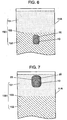
- the status is shown in Fig. 7. A few seconds after such floating, the coat 23 is collapsed as shown in Fig. 8, and simultaneously, the bubble layer 20 is reduced in thickness. As a result, the buoyancy is decreased, causing the droplet to move downward toward the second gelatinized starch solution again.
- the cooling solution 150 for the third experiment was prepared as described in the following.
- As the second solution 152 30g of potato starch was put into water to make it 1,000cc as a whole, and then the solution was heated up to 80°C and gelatinized with stirring. Namely, the first gelatinized starch solution in the first experiment was employed.
- As the first solution 151 10g of potato starch was put into water to make it 1,000cc as s whole, and then the solution was heated up to 80°C and gelatinized (hereafter it is called the third gelatinized starch solution).
- the third gelatinized starch solution is lower in viscosity than the first gelatinized starch solution, second solution 152, but higher than water.
- the cooling solution 150 prepared in this way since each solution is gelatinized, the solutions do not become mixed with each other for a few hours to scores of hours almost same as in the above experiments, making it possible to maintain the stable status of the two layers.
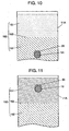
- the liquid glass droplet 10 stops moving down due to the action of the resultant buoyancy.
- the liquid glass droplet 10 is cooled down to a temperature below the glass transfer temperature and turns into glass bead 101 as shown in Fig. 13, and simultaneously, the bubble layer 20 is reduced.
- the glass bead 101 begins to move downward slowly.
- the behavior after Fig. 12 is same as in the first experiment.
- the cooling solution 150 for the fourth experiment was prepared as described in the following.
- As the second solution 152 synthetic paste made from commercially available polyvinyl alcohol was employed.
- As the first solution 151 water that is noncombustible liquid lower in viscosity than the synthetic paste was used. Also in this case, the solutions do not become mixed with each other for a few hours to scores of hours, making it possible to maintain the stable status of the two layers.
- the behavior of liquid glass droplet 10 after dripping into the cooling solution 150 until turning into glass bead 101 is nearly the same as in the first experiment, and the description is omitted.
- the cooling solution 150 for the first comparative experiment was prepared.
- the second solution 152 10g of potato starch was put into water to make it 1,000cc as a whole, and the solution was heated up to 80°C and gelatinized with stirring.
- the third gelatinized starch solution used as the first solution 151 in the third experiment was employed.
- water was used as the first solution 151.
- the solutions do not become mixed with each other for a few hours to scores of hours, making it possible to maintain the stable status of the two layers.
- the bubble layer 20 around the liquid glass droplet 10 swells slightly upward but not so greatly as in the first experiment and the second experiment. This is because the gelatinized starch is low in concentration. Accordingly, the buoyancy then obtained is not enough to stop the liquid glass droplet 10 but it only causes the liquid glass droplet 10 to lower its falling speed, and the liquid glass droplet 10 still continues going downward.
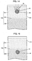
- the liquid glass droplet 10 is cooled while going downward, and when the temperature becomes less than the glass transfer temperature, it turns into glass bead 101, and then, the bubble layer 20 is hardly generated. It is shown in Fig. 16.
- Table 1 First solution Second solution Sphericity (%) Results of surface observation First experiment Water First gelatinized starch solution 98-99.5 Fissure, crack, vacuum bubble rate: ⁇ 5% Second experiment Water Second gelatinized starch solution 97-99 Fissure, crack, vacuum bubble rate: ⁇ 5% Third experiment Third gelatinized starch solution First gelatinized starch solution 95-97 Fissure, crack, vacuum bubble rate: ⁇ 5% Fourth experiment Water Synthetic paste 98-99.5 Fissure, crack, vacuum bubble rate: ⁇ 5% First comparative experiment Water Third gelatinized starch solution 96-98 Fissure, crack, vacuum bubble: 100%
- the sphericity is 96 to 98%, and the generation rate of fissure, crack and vacuum bubble (hereafter these are called defects) is 100%.
- the second experiment, and the fourth experiment it has been found that the sphericity is worse and the generation rate of defects is very high. Accordingly, in the first comparative experiment, it has confirmed that the yield of glass bead 101 is greatly lowered resulting in poor productivity.
- the first experiment through the fourth experiment it has been observed that the sphericity slightly worsens as the potato starch, the second solution 152, is reduced in concentration.
- the results obtained are excellent because the generation rates of defects are all less than 5% that is the allowable limit value.
- the sphericity required is 95% or over, and therefore, all the values are acceptable with respect to sphericity including those obtained in the first comparative experiment.
- the defect generation of glass bead 101 is related with the concentration of gelatinized starch. That is, as is seen in the first experiment, the second experiment, and the third experiment, when the potato starch contained in the gelatinized starch solution being the second solution 152 is 20g or over as against 1,000cc of water, the value obtained with respect to the defect generation rate is smaller than 5% that is the allowable limit value. However, as is apparent in the first comparative experiment, when potato starch is 10g as against 1000cc of water, that is, 10g/1000cc, the defect generation rate is 100%.
- the concentration of gelatinized starch solution as the second solution 152 increases, and the falling speed of glass bead 101 becomes very slow. Consequently, the productivity is greatly lowered. Accordingly, in order to assure excellent sphericity without worsening the productivity, it is desirable to set the concentration in a range from 20g to 40g.
- sphericity is influenced by the impact generated when liquid glass droplet 10 thrusts into the cooling solution 150.
- the fact has been found through experiments executed by changing the viscosity of the first solution 151. This is because the thrust impact is greater when the viscosity is higher, causing the liquid glass droplet 10 to be deformed.
- the sphericity is lower in the third experiment than in the first experiment and the second experiment because the third gelatinized starch solution used as the first solution 151 in the third experiment is higher in viscosity as compared with the others. Accordingly, the first solution 151 is desirable to be as low in viscosity as possible.
- the dripping direction is desirable to be vertical to the cooling solution in order to decrease the impact.
- setting the viscosity of the first solution 151 in accordance with the weight of liquid glass droplet 10 and the distance to the surface of the cooling solution it is also possible to obtain the glass bead 101 with intended flatness as the deforming action in thrusting into the first solution 151 is utilized.
- the fourth experiment synthetic paste made from polyvinyl alcohol is used as the second solution 152, and the sphericity obtained is equivalent to that obtained in the first experiment, and the defect generation rate is less than 5% that is the allowable limit value. Accordingly, as the cooling solution 150, it is preferable to use water as the first solution 151 and synthetic paste as the second solution 152. Also, when a synthetic paste lower in viscosity that the synthetic paste as the second solution 152 is used as the first solution 151, the results obtained are nearly same as in the third experiment.
- potato starch is used, but corn starch, sweet potato starch, rice starch, and like starch are also available, which can be similarly used in the form of gelatin by mixing them with water in appropriate ratios. However, it is most preferable to use potato starch which can be increased in viscosity with less quantity when gelatinized.
- the influences caused by the temperatures of cooling solution 150 were examined.
- the manufacturing conditions are same as in the first experiment described in the preferred embodiment 2, using the same cooling solution 150.
- the temperature of the cooling solution 150 was varied to 55°C, 60°C, and 70°C.
- 280 pieces of glass beads were prepared as the samples in order to observe the sphericity and surfaces.
- the methods of sphericity and surface observation are same as described in the preferred embodiment 2.
- the sphericity ranges from 97% to 99%, but the defect generation rate is 100%.
- the solution temperature is 60°C, the sphericity ranges from 98% to 99.5%, and at 70°C, it ranges from 98.5% to 99.5%, showing a tendency that the higher the solution temperature, better is the sphericity.
- the defect generation rate of glass bead 101 is as good as less than 5%, the allowable limit value.
- the solution temperature is 55°C, only the surface of liquid glass droplet 10 is rapidly cooled and vacuum bubbling is liable to take place, and it has been found that the defect generation rate is greatly increased as a result. Judging from the result, in order to produce glass bead 101 with excellent sphericity and less rate of defect generation, it is necessary to set the temperature of the cooling solution 150 to 60°C or over.
- the upper limit of the temperature only required is to maintain the stable state of the cooling solution 150, and for example, when water is used as the first solution, it is preferable to set the temperature to 100°C, boiling point, or lower.
- oil or starch solution is used as the cooling solution, including the surface portion with which the liquid glass droplet first comes into contact, it is preferable to set the temperature to the boiling point or lower of the solution used.
- the second solution 152 the first gelatinized starch solution same as in the first experiment of the preferred embodiment 2 was used. Also, the first gelatinized starch solution as the second solution 152 was filled into large-diameter pipe 11A of liquid glass droplet receiver 11 so as to make the solution level 150mm, on which the first solution 151 was poured to make the solution level 50mm.
- the temperature of the cooling solution 150 formed of these solutions was set to 50°C, and the distance from dripping nozzle 2A to the first solution 151 was set to 20mm. Also, molten glass 4 used is borosilicate glass melted by heating at 1,150°C, which was dripped by 60mg.
- the first addition water water with nonionic surfactant added by 0.01wt%
- the cooling solution 150 thus configured, the behavior of liquid glass droplet 10 after dripping into the cooling solution 150 until turning into glass droplet 101 will be described with reference to Fig. 17 to Fig. 21.
- the liquid glass droplet 10 thrusts into the first addition water that is the first solution 151 bubble layer 20 is formed around the liquid glass droplet 10 as shown in Fig. 17. Further, fine bubbles 21 are generated from the bubble layer 20 and reach the surface of the first addition water and then disappear.
- the liquid glass droplet 10 with the bubble layer 20 formed therearound passes through interface 153 and goes down into the first gelatinized starch solution that is the second solution 152.
- the bubble layer 20 largely swells upward as shown in Fig. 18, causing buoyancy to be generated, and then the liquid glass droplet 10 stops going downward.
- the liquid glass droplet 10 moves up into the first addition water along with the bubble layer 20 formed therearound and also with coat 23 composed of the first gelatinized starch solution formed around the periphery thereof.
- the behavior so far is nearly same as in the second experiment of the preferred embodiment 2.
- the first addition water contains nonionic surfactant, and the surfactant acts to prevent the coat 23 from collapsing, and then the liquid glass droplet 10 floats in the first addition water while repeating slight up-and-down motions for a little more than 10 seconds.
- the temperature of the liquid glass droplet 10 is lowered, the bubble layer 20 is reduced in thickness and in buoyancy, then the liquid glass droplet again goes down into the first gelatinized starch solution as shown in Fig. 20.
- the second addition water water with nonionic surfactant added by 0.001wt%
- the third addition water water containing 0.02wt% of nonionic surfactant (hereafter called the third addition water) was used.
- the composition is same as in the first experiment of the preferred embodiment 2, but there is a difference that the solution temperature is 50°C.
- the defect generation rate is related with the concentration of nonionic surfactant added into the first solution 151.
- the defect generation rate tends to increase irrespective of the concentration.
- the defect generation rate is 100% nearly the same as the results (see Table 2) obtained with the temperature of cooling solution 150 set to 55°C. Consequently, it is necessary to set the additive concentration to 0.001w% or over.
- the defect generation rate is about 10%, resulting in exceeding 5% that is the allowable limit value.
- the reasons for this are as follows.
- the concentration of surfactant being 0.02wt% or over gives rise to reaction between the gelatinized starch and the surfactant, thereby causing the bond of gelatinized starch molecules to be easily broken.
- the coat 23 is lowered in starch strength, reacting with the surfactant, then the coat 23 becomes liable to collapse. Consequently, fine bubbles from the bubble layer 20 easily pass through the coat 23, causing the bubble layer 20 to be reduced in size. Judging from such phenomenon, it can be predicted that defects including vacuum bubbles in particular are generated as the surface layer of liquid glass droplet 10 is rapidly cooled.
- the coat 23 effectively acts to maintain the stable status. That is, even when the liquid glass droplet 10 covered with the bubble layer 20 and the coat 23 again comes up into the first solution 151, the coat 23 is hard to collapse due to the action of the surfactant, and the stable status of the bubble layer 20 is maintained. As a result, the liquid glass droplet 10 with buoyancy acted thereon may float in the first solution 151 for a little more than 10 seconds while repeating slight up-and-down motions.
- the additive concentration of surfactant is desirable to be in a range from 0.001wt% to 0.01wt%.
- cooling solution 150 being same as for the fifth experiment of the preferred embodiment 4, the influences with the temperature varied were examined. Under the three conditions of 45°C, 50°C and 60°C as the temperature of cooling solution 150, 280 pieces of glass beads were prepared to execute the evaluation same as in the preferred embodiment 4.
- cooling solution 150 being 45°C is too low, and even when the liquid glass droplet 10 comes into contact with the first addition water, the bubble layer generated is insufficient, then the first addition water and the liquid glass droplet 10 become easier to directly contact with each other. As a result, only the surface portion of the liquid glass droplet 10 is rapidly cooled, making bumping noise, and vacuum bubbles are generated in the liquid glass droplet 10.
- the behavior of the liquid glass droplet 10 in the cooling solution 150 is nearly the same as in the fifth experiment of the preferred embodiment 4.
- the sphericity of glass bead 101 produced under the condition is 98.5% to 99.6%.
- the defect generation rate is less than 1%. From these results, it has been found that when water containing surfactant is used as the first solution 151, it is necessary at least to set the temperature of the first solution 151 of the cooling solution 150 to 50°C or over. As to the upper limit of the temperature, there is no requirement provided that the temperature is enough to stabilize the cooling solution 150. For example, when water containing surfactant is used as the first solution 151, it is preferable to set the temperature to 100°C, boiling point of water, or lower.
- the present invention is not limited to this configuration.
- the cooling solution 150 which uses synthetic paste mainly containing polyvinyl alcohol as the second solution 152 and surfactant contained water as the first solution 151.
- glass beads with excellent sphericity and less rate of defect generation can be obtained.
- the surfactant added into the water used as the first solution it is preferable to use nonionic surfactant, cationic surfactant, anionic surfactant or amphoteric surfactant.
- nonionic surfactant being excellent in stability is a most preferable material for mass-production of glass beads.
- the present invention is not limited to the contents described in the preferred embodiment 2 to the preferred embodiment 5.
- oil as the cooling solution, making the region with which the liquid glass droplet first comes into contact lower in viscosity and the oil at the lower portion thereof higher in viscosity.
- the bubble layer generated around the liquid glass droplet can be covered with a coat having the composition of the second solution, thereby making it possible to stabilize the bubble layer.
- the amount of liquid glass droplet is 60mg
- the diameter of glass bead is about 3mm
- glass beads which are higher in sphericity and lower in generation rate of deflects such as crack and vacuum bubbles can be produced by a structurally simple apparatus and method.
- the glass beads it is possible to execute hot mold press-forming without polishing an to manufacture inexpensive lenses with excellent shape accuracy.
Landscapes
- Chemical & Material Sciences (AREA)
- Engineering & Computer Science (AREA)
- Materials Engineering (AREA)
- Organic Chemistry (AREA)
- Manufacturing & Machinery (AREA)
- Life Sciences & Earth Sciences (AREA)
- Chemical Kinetics & Catalysis (AREA)
- General Chemical & Material Sciences (AREA)
- Geochemistry & Mineralogy (AREA)
- Glass Compositions (AREA)
- Joining Of Glass To Other Materials (AREA)
Abstract
Description
- The present invention relates to a method and apparatus for producing glass beads, particularly to a method for producing glass beads as preform material used for manufacturing optical lenses by press-forming.
- Recently, not only optical equipment and digital cameras but cellular phones and other devices are equipped with cameras, and there is an increasing demand for low-cost lenses which are smaller in size and higher in performance. As a method for manufacturing such lenses, a hot mold press-forming method for preform material is widely employed in place of a conventional glass sheet polishing method. In this manufacturing method, a lens is formed by hot press-forming after arranging glass beads, preform material, between metal molds having same curved surfaces as those of the lens. In this case, for increasing the shape accuracy of the lens to be finally formed, it is desirable that the glass beads, preform material, be as spherical as possible and free from defects such as internal bubbling. The reasons for this are as follows. Namely, when glass beads are excellent in sphericity, no bias load will be applied to the glass beads in the initial state of pressing in metal molds, and as a result, it is possible to enhance the accuracy of the lens formed by press-forming.
- As a method for producing such glass beads as preform material, available is a method of grinding and polishing glass into spheres. However, in the glass grinding and polishing method, there is a great loss of glass material, and also, much time is required for producing glass beads and it is unable to improve the productivity.
- Accordingly, in the Japanese Laid-open Patent H2-14839, disclosed is a method for producing glass beads in which glass is melted in a platinum pot, and the molten glass is dripped into air from a platinum nozzle connected to the pot, and the dripped molten glass is cooled in a state of being floated by a flow of air jetted above the receiving mold provided with an air jetting orifice at the bottom thereof. Also, in the Japanese Laid-open Patent H10-291824, disclosed is a method of cooling and hardening drops of molten glass thrown into a solution having cleaning effects. In this method, alcohol or a mixture of alcohol and water is used as the solution, and it is disclosed that glass beads with excellent sphericity can be manufactured while shortening the dripping distance.
- However, in the case of producing a glass bead by cooling while making it floated in air, it is relatively difficult to cool a drop of molten glass in a state of being precisely floated by air flow. As a result, the drop of molten glass may sometimes come into direct contact with the inner surface of the receiving mold. In that case, there arises a problem such that the drop of molten glass hardens as it is deformed or strained. Further, when a plurality of drops of molten glass are dripped into same receiving mold, the drops of molten glass come into contact with each other to be broken, cracked or hardened, and it is necessary to take out the glass beads before dripping the next molten glass. Accordingly, there is a problem of poor productivity.
- Also, in the method of producing glass beads by cooling drops of molten glass thrown into alcohol or the mixture of alcohol and water, defects such as breaking of glass beads and vacuum bubbling are liable to take place, and the yield as preform material cannot be improved, and it is relatively difficult to manufacture highly accurate lenses at low costs.
- The present invention is intended to solve the above problems, and the purpose of the invention is to provide a producing method and apparatus for glass beads used as preform material for forming lenses, which is capable of continuous and highly efficient production of glass beads with excellent sphericity.
- In order to achieve the above purpose, the glass beads producing method and apparatus of the present invention comprises the following steps and configurations.
- The method for producing glass beads of the present invention comprises a step of dripping a liquid glass droplet into cooling solution by dripping molten glass from a nozzle, and a step of cooling wherein during a period when the liquid glass droplet is cooled down to a temperature lower than the glass transfer temperature in the cooling solution, the liquid glass droplet is covered with a bubble layer generated as the cooling solution is vaporized, and the liquid glass droplet in the cooling solution is slowly cooled and lowered in falling speed.
- In such a manufacturing method, a bubble layer is formed over the entire periphery of the liquid glass droplet in the cooling solution, and the bubble layer is continuously formed until the temperature becomes lower than the glass transfer temperature. Accordingly, the glass droplet is slowly cooled, during which period the high-temperature liquid glass droplet is spherically formed due to the surface tension thereof, and thereby, a glass bead with excellent sphericity can be produced.
- Also, the apparatus for producing glass beads of the present invention comprises a melting pot for heating and melting glass, a nozzle for dripping molten glass in the melting pot, which is disposed at the bottom of the melting pot, and a liquid glass droplet receiver filled with cooling solution for cooling the liquid glass droplet dripped from the nozzle, which is disposed under the nozzle, wherein the cooling solution is made from a material that forms a bubble layer around the liquid glass droplet as the cooling solution is vaporized due to the heat of the liquid glass droplet during a period when the liquid glass droplet is cooled down to a temperature lower than the glass transfer temperature in the cooling solution.
- In such a manufacturing apparatus, a bubble layer is formed over the entire periphery of the liquid glass droplet in the cooling solution, and the bubble layer is continuously formed until the temperature becomes lower than the glass transfer temperature, and as a result, the liquid glass droplet is slowly cooled, during which time the high-temperature liquid glass droplet is spherically formed due to the surface tension thereof, and thereby, a glass beard with excellent sphericity can be produced.
- Further, the apparatus comprises a dripping means for dripping molten glass wherein an air feeder is connected to the melting pot being sealed, and high-pressure gas under control is introduced from the air feeder into the melting pot, and a moving mechanism wherein the liquid glass droplet receiver can be two-dimensionally moved in the horizontal direction. Thus, the manufacturing apparatus moves the liquid glass droplet receiver in synchronism with the dripping means, and thereby, it is possible to produce a glass bead with excellent mass-productivity.
-
- Fig. 1 is a schematic block diagram of a glass bead producing apparatus of the present invention.
- Fig. 2 to Fig. 4 are schematic views showing a glass bead forming process in the
preferred embodiment 1 of the present invention. - Fig. 5 to Fig. 10 are schematic views showing a glass bead forming process in the case of using the cooling solution of the second experiment in the
preferred embodiment 2 of the present invention. - Fig. 11 to Fig. 13 are schematic views showing a glass bead forming process in the case of using the cooling solution of the third experiment in the
preferred embodiment 2 of the present invention. - Fig. 14 to Fig. 16 are schematic views showing a glass bead forming process in the case of using the cooling solution of the first comparative experiment in the
preferred embodiment 2 of the present invention. - Fig. 17 to Fig. 21 are schematic views showing a glass bead forming process in the case of using the cooling solution of the fifth experiment in the
preferred embodiment 4 of the present invention. - Fig. 1 is a schematic block diagram of a glass beads producing apparatus of the present invention. This apparatus is nearly vertically arranged as a whole. That is, a platinum pot as melting
pot 2 andelectric furnace 1 arranged so as to surround theplatinum pot 2 are arranged at the top of liquidglass droplet receiver 11. At the bottom of theplatinum pot 2 is disposed drippingnozzle 2A extended from theplatinum pot 2. Theplatinum pot 2 is filled withmolten glass 4 in a state of being melted, and themolten glass 4 is stirred by stirringblade 5 made of platinum so that its whole uniformity is maintained for a long period of time. Further, at the top of theplatinum pot 2 is securely disposedmetal lid 7 which is fastened to theplatinum pot 2 via O-ring seal 8. Also, the gap between themetal lid 7 and stirringblade rotating shaft 5A is sealed with well-known sealingmember 9 made from resilient material such as rubber so that the stirringblade 5 can be freely rotated from outside. - Further, the
metal lid 7 is integrally furnished withair feeder 7A. It is possible to introduce high-pressure air being controlled by control 'unit 6 into the space of theplatinum pot 2 through theair feeder 7A. Theair feeder 7A and thecontrol unit 6 make up a dripping means. With the pressure of the high-pressure air introduced by theair feeder 7A into theplatinum pot 2,molten glass 4 can be dripped at proper intervals by the amount determined by the nozzle diameter of the drippingnozzle 2A. When organic material is used as the O-ring seal 8 and the sealingmember 9, it is desirable to cool the peripheries thereof. Also, it is preferable to separately make theair feeder 7A and securely dispose it via a seal instead of its integral configuration with themetal lid 7. Further, a platinum pot is used as themelting pot 2, but there is no particular restrictions provided that the pot is made of a material that does not react with molten glass. - In an apparatus having such a configuration, when
molten glass 4 is dripped from drippingnozzle 2A, the weight ofliquid glass droplet 10 dripped from the tip of drippingnozzle 2A is determined by the outer diameter of drippingnozzle 2A and the surface tension of glass, and the relationship can be obtained by formula (1).
liquid glass droplet 10, g is gravitational acceleration, D is outer diameter of drippingnozzle 2A, and γ is surface tension of molten glass. - As is obvious from formula (1),
liquid glass droplet 10 can be dripped by the weight determined by the outer diameter D of drippingnozzle 2A. However, if it is naturally dripped without applying pressures to the surface ofmolten glass 4, it will take much more time for dripping; and the productivity cannot be improved. In the case of the producing apparatus of this embodiment, high-pressure air is introduced fromair feeder 7A into the space ofplatinum pot 2 in order to apply pressures to the surface ofmolten glass 4, thereby enabling the dripping at proper intervals, and it is possible to greatly improve the productivity for producing glass beads. - Under the dripping
nozzle 2A is arranged liquidglass droplet receiver 11 spaced apart from the tip of the drippingnozzle 2A. The liquidglass droplet receiver 11 comprises large-diameter pipe 11A,tapered portion 11B formed at the lower part of the large-diameter pipe 11A,valve 11C connected to the lower part thereof, and small-diameter pipe 11D connected to thevalve 11C. Further,hose 12 is connected to the small-diameter pipe 11D, and also,replaceable hose 14 is connected to thehose 12 viavalve 13. The opening of drippingnozzle 2A is arranged in such manner that theliquid glass droplet 10 vertically drops to the surface ofcooling solution 150. - The liquid
glass droplet receiver 11 is filled withcooling solution 150 disposed of at least two kinds of solutions different in viscosity. That is,first solution 151 of low viscosity is disposed at the upper part of liquidglass droplet receiver 11, andsecond solution 152 higher in viscosity than thefirst solution 151 is filled thereunder. As for the boundary between thefirst solution 151 and thesecond solution 152, a material composition by which relativelyclear interface 153 can be formed is selected. Also, the hose from thevalve 11C of liquidglass droplet receiver 11 to thereplaceable hose 14 is filled withwater 17. And,removable clamp 14A is fitted to one end of thereplaceable hose 14, which serves to prevent water leakage during the production ofglass beads 101, and when taking outglass beads 101 produced, theclamp 14A can be removed to easily take out theglass beads 101. - Further, the liquid
glass droplet receiver 11 is provided with liquidtemperature control unit 18 for setting thecooling solution 150 to the predetermined temperature. The liquidtemperature control unit 18 is not only able to control theentire cooling solution 150 to a uniform temperature, but also, for example, able to keep thefirst solution 151 and thesecond solution 152 at the predetermined temperatures respectively and to make thecooling solution 150 have a continuous temperature gradient. - Also, when dripping the
molten glass 4 continuously into thecooling solution 150, it is required to devise so that theliquid glass droplets 10 come into contact with each other in thecooling solution 150. Accordingly, movingmechanism 19 for changing the dripping position is disposed in that the liquidglass droplet receiver 11 is two-dimensionally moved in the horizontal direction in accordance with the dripping duct by controlling the movingmechanism 19 from thecontrol unit 6 of the dripping means. - The
liquid glass droplets 10 dripped from the drippingnozzle 2A are cooled in thecooling solution 150 made up of thefirst solution 151 and thesecond solution 152 and then turn intoglass beads 101. Theglass beads 101 go down to thereplaceable hose 14, passing through thevalve 11C being open, thehose 12, and thevalve 13 being open, and are collected in thereplaceable hose 14. In the apparatus of this preferred embodiment, thereplaceable hose 14 serves as a collecting portion. When a specific amount ofglass beads 101 has been collected, thevalve 13 is closed and thereplaceable hose 14 is removed, and then theglass beads 101 are taken out of thereplaceable hose 14. The length of thereplaceable hose 14 can be determined according to the required amount of glass beads collected. Thehose 12 and thereplaceable hose 14 are filled withwater 17 in order to improve the fluidity of theglass beads 101 in these hoses. After taking out theglass beads 101 collected, thereplaceable hose 14 newly filled withwater 17 is fitted to thevalve 13, and thus, theglass beads 101 can be collected again by opening thevalve 13. - The actions of the
cooling solution 150 when producingglass beads 101 by such apparatus will be described with reference to Fig. 2 to Fig. 4. Fig. 2 to Fig. 4 are schematic views showing the step of forming theglass beads 101 whereinliquid glass droplets 10 are dripped into thecooling solution 150 in the liquidglass droplet receiver 11. In the following description, the first solution is water as thecooling solution 150, and thesecond solution 152 is gelatinized starch solution (hereafter called the first gelatinized starch solution) prepared by heating and stirring 30g of potato starch at 80°C while dissolving it in 1000cc of water, and the temperature of thecooling solution 150 made up of these solutions is controlled to 60°C as an example. Also, borosilicate glass is used as themolten glass 4, which is heated up to 1150°C and dripped in a molten status in the description. - The
liquid glass droplet 10 dripped from the drippingnozzle 2A by the weight determined by the nozzle diameter first comes in contact with thefirst solution 151 that is water. At the time, since theliquid glass droplet 10 is very hot, the water or thefirst solution 151 around theliquid glass droplets 10 is vaporized, thereby formingbubble layer 20 around theliquid glass droplet 10 as shown in Fig. 2. Fine bubbles 21 are generated from thebubble layer 20, but the fine bubbles 21 go up to the surface of thefirst solution 151 and then disappear. In this condition, theliquid glass droplet 10 is still very hot, causing thefirst solution 151 to be vaporized and the fine bubbles 21 to be generated, and it goes downward in thefirst solution 151 with thebubble layer 20 still formed therearound. - When the
liquid glass droplet 10 further goes downward and passes through theinterface 153, theliquid glass droplet 10 with thebubble layer 20 formed therearound goes into the first gelatinized starch solution that is thesecond solution 152. Even in thesecond solution 152, theliquid glass droplet 10 is still very hot, and thesecond solution 152 is continuously vaporized, keeping thebubble layer 20 formed therearound. At the time, since thebubble layer 20 is surrounded by thesecond solution 152 of high viscosity, the fine bubbles 21 generated from thebubble layer 20 will take much time to go through thesecond solution 152 of high viscosity. Therefore, as shown in Fig. 3, thebubble layer 20 swells at the top thereof. Namely, the first gelatinized starch solution as thesecond solution 152 acts as a coat to enclose the entire periphery of thebubble layer 20, thereby preventing thebubble layer 20 from disappearing. Even in that condition, theliquid glass droplet 10 is still very hot, and vapor is continuously generated therearound, giving rise to the growth of thebubble layer 20. As a result, theliquid glass droplet 10 stops going downward due to buoyancy that acts upon theliquid glass droplet 10. - When the
liquid glass droplet 10 is slowly cooled and becomes lower than the glass transfer temperature, theliquid glass droplet 10 hardens and turns intoglass bead 101. When theglass bead 101 is at such a temperature, thebubble layer 20 therearound is gradually absorbed by the first gelatinized starch solution that is thesecond solution 152 therearound, and becomes smaller in size. Consequently, since the weight ofglass bead 101 exceeds the buoyancy, theglass bead 101 slowly goes downward as shown in Fig. 4. Then, the temperature of theglass bead 101 is lower than the glass transfer temperature. Accordingly, even when thebubble layer 20 disappears from around theglass bead 101, and theglass bead 101 comes into direct contact with the first gelatinized starch solution, it will not cause burning of the starch components, organic matters such as amylose or amylopectin. - When the weight of
liquid glass droplet 10 is about 60mg, the time required for theliquid glass droplet 10 to be cooled in a state of floating while being surrounded by thebubble layer 20 is about 12 to 14 seconds. That is, despite thatcooling solution 150 is used for the manufacture, the effect obtained is same as in a manufacturing method wherein it is naturally dropped and slowly cooled in air for 12 to 14 seconds. Consequently, it is possible to obtainglass beads 101 with excellent sphericity and less defects such as cracks and vacuum bubbles. - Also, as described above, in the manufacturing method of the present invention, the floating time of the
liquid glass droplet 10 surrounded bybubble layer 20 ranges from 12 seconds to 14 seconds. Accordingly, when theliquid glass droplet 10 is dripped from the drippingnozzle 2A into same portion of thecooling solution 150 in tact time of 12 seconds or less, theliquid glass droplets 10 come into contact with each other, sometimes causing them to be bonded to each other or cracked. The are not spherical in a state of being bonded to each other and cannot be used as preform material. In order to prevent such phenomenon and to shorten the dripping tact time, there is provided the movingmechanism 19 which moves the position ofcooling solution 150 two-dimensionally in the horizontal direction every dripping of theliquid glass droplet 10. The movingmechanism 19 can be moved by thecontrol unit 6 of the dripping means in accordance with the dripping tact time. It is preferable to freely select the way of moving, for example, linear movement over a distance, rotational movement over a distance or a combination of these every dripping, provided that the nextliquid glass droplet 10 is not dripped into same portion before theliquid glass droplet 10 is solidified. - In the present preferred embodiment, as for the behavior in the
cooling solution 150 until theliquid glass droplet 10 turns intoglass bead 101, thesecond solution 152 is a first gelatinized starch solution in the description. In this manufacturing apparatus, however, it is not limited to this material. As starch, it is also possible to use corn starch, sweet potato starch, or rice starch as well as potato starch that is the first gelatinized starch solution. In this case, it is desirable to use potato starch because the viscosity can be kept high even with same amount of starch in a state of being gelatinized. - Also, as the cooling solution, it is also possible to use a solution of which the surface portion firstly coming into contact with the liquid glass droplets is lower in viscosity than the region thereunder. Further, it is desirable to drip the liquid glass droplets in a direction vertical to the cooling solution. Due to such configuration, it is possible to prevent the liquid glass droplets for being deformed by shocks when dripped into the cooling solution and to obtain glass beads with higher sphericity. Moreover, by using an noncombustible solution for the surface portion of the cooling solution, firstly coming into contact with the liquid glass beads, it is possible to prevent the generation of a fire or the like even in case hot liquid glass droplets of about 1,000°C are dripped into the cooling solution.
- Also, synthetic paste can be used as the cooling solution, and same effects as in the case of gelatinized starch solution can be obtained. Further, similar effects can be obtained by using, as the cooling solution, a configuration comprising an oil whose surface portion firstly coming into contact with the liquid glass droplets is lower in viscosity and an oil disposed thereunder which is higher in viscosity than the surface portion.
- It is also preferable to use a solution including surfactant as the cooling solution. In this case, as the cooling solution, it is preferable to employ a two-layer configuration in which surfactant-contained water is disposed as the surface portion firstly coming into contact with the liquid glass droplets, and gelatinized starch solution or synthetic paste solution is disposed thereunder. In this case, the coat of the gelatinized starch solution or synthetic paste solution formed around the bubble layer covering the liquid glass droplet due to the action of the surfactant is stabilized. Accordingly, the bubble layer covering the entire surface of the liquid glass droplet will be continuously maintained for a longer time. As a result, a larger bubble layer will be formed, causing the liquid glass droplet to be given greater buoyancy and its entire body to be floated along with a rotational force. In this way, the liquid glass droplet is gradually cooled, and due to the efficient actions of surface tension and centrifugal forces generated due to rotation, it is possible to more precisely prevent the generation of vacuum bubbles or cracks and at the same time to produce glass beads with excellent sphericity.
- Also, as the shape of the liquid glass droplet receiver, the region where the liquid glass droplets turn into glass beads is larger in area, which is gradually reduced in area downwards. Accordingly, glass beads can be easily introduced into the collector portion. Also, since the collector portion is replaceable, it is possible to remove or attach only the replaceable hose, collector portion, while stopping the cooling solution, and in this way, the glass beads can be efficiently taken out.
- By using the manufacturing apparatus described above, specific description will be given in the following with respect to a method for producing glass beads by using various cooling solutions of the present invention. In the present preferred embodiment,
cooling solution 150 filled into the large-diameter pipe 11A of liquidglass droplet receiver 11 is of two-layer configuration, and its composition is varied to produce glass beads. The liquid level of thesecond solution 152, lower part of thecooling solution 150, is 150mm, and thefirst solution 151 in liquid level of 50mm is disposed above thesecond solution 152. Further, the temperature ofcooling solution 150 is controlled to 60°C by liquidtemperature control unit 18. Also, the distance from the drippingnozzle 2A to the surface offirst solution 151 is 20mm, andliquid glass droplet 10 made of borosilicate glass melted at 1150°C is dripped by weight of 60mg to produce a glass bead. - The
cooling solution 150 for the first experiment was prepared as described in the following. As thesecond solution 152, gelatinized potato starch solution was employed. After dissolving 30g of potato starch in water to make it 1,000cc as a whole, the solution was heated up to 80°C and gelatinized with stirring. Namely, it is the same as the first gelatinized starch solution in thepreferred embodiment 1. Also, thefirst solution 151 used is lower in viscosity than the first gelatinized starch solution being thesecond solution 152, which is water being noncombustible. As to thecooling solution 150 prepared in this way, the upper part,first solution 151, is water, and the lower part,second solution 152, is the first gelatinized starch solution. Therefore, both solutions do not become mixed with each other for about a few hours to scores of hours, making it possible to maintain the stable status of the two layers. That is, thecooling solution 150 is same in composition and conditions as the example in thepreferred embodiment 1. Accordingly, when theliquid glass droplet 10 is dripped into thecooling solution 150, the behavior of theliquid glass droplet 10 until turning intoglass bead 101 in thecooling solution 150 is same as the behavior described in thepreferred embodiment 1, and therefore, the description is omitted. - The
cooling solution 150 for the second experiment was prepared as described in the following. As thesecond solution 152, 20g of potato starch was put into water to make it 1,000cc, and the solution was heated up to 80°C and gelatinized with stirring (hereafter it is called the second gelatinized starch solution). Also, thefirst solution 150 used is water the same as in the first experiment. As to thecooling solution 151 prepared in this way, both solutions do not become mixed with each other for a few hours to scores of hours the same as in the first experiment, making it possible to maintain the stable status of the two layers. - In the case of the second experiment, the behavior of the
liquid glass droplet 10 after dripping until turning intoglass bead 101 will be described with reference to Fig. 5 to Fig. 10. When theliquid glass droplet 10 is dripped into the water,first solution 151, thenbubble layer 20 is formed around theliquid glass droplet 10 as shown in Fig. 5. Fine bubbles 21 are generated from thebubble layer 20 and move upward in the water,first solution 151, and disappear reaching the surface thereof. This is completely same as in the case of the first experiment. While indicating such a phenomenon, theliquid glass droplet 10 moves downward in the second gelatinized starch solution that is thesecond solution 152. When it goes into the second gelatinized starch solution, since the second gelatinized starch solution is higher in viscosity than the water of thefirst solution 151, the fine bubbles 21 generated from thebubble layer 20 are enclosed therein, causing thebubble layer 20 to be greatly swelled as shown in Fig. 6. As a result, theliquid glass droplet 10 stops moving downward. - The second gelatinized starch solution in the second experiment is lower in concentration and in viscosity than the first gelatinized starch solution in the first experiment. Therefore, the
liquid glass droplet 10 is floated due to buoyancy up into the water,first solution 151, together with thebubble layer 20 andcoat 23 composed of the components of the second gelatinized starch solution formed in the peripheral region of the bubble layer. The status is shown in Fig. 7. A few seconds after such floating, thecoat 23 is collapsed as shown in Fig. 8, and simultaneously, thebubble layer 20 is reduced in thickness. As a result, the buoyancy is decreased, causing the droplet to move downward toward the second gelatinized starch solution again. - As shown in Fig. 9, around the
liquid glass droplet 10 which has again moved down into the second gelatinized starch solution that is thesecond solution 152, thebubble layer 20 which has greatly swelled upward is again formed, causing theliquid glass droplet 10 to stop moving downward. After that, when theliquid glass droplet 10 is cooled down to a temperature below the glass transfer temperature, thebubble layer 20 around theliquid glass droplet 10 is reduced. As thebubble layer 20 is reduced, the liquid glass droplet turns intoglass bead 101 and begins to move downward as shown in Fig. 10. As described above, in the second experiment, theliquid glass droplet 10 moves down into thesecond solution 152 and again moves up into thefirst solution 151, and this is the point of big difference from the first experiment. - The
cooling solution 150 for the third experiment was prepared as described in the following. As thesecond solution 152, 30g of potato starch was put into water to make it 1,000cc as a whole, and then the solution was heated up to 80°C and gelatinized with stirring. Namely, the first gelatinized starch solution in the first experiment was employed. Also, as thefirst solution 151, 10g of potato starch was put into water to make it 1,000cc as s whole, and then the solution was heated up to 80°C and gelatinized (hereafter it is called the third gelatinized starch solution). The third gelatinized starch solution is lower in viscosity than the first gelatinized starch solution,second solution 152, but higher than water. As to thecooling solution 150 prepared in this way, since each solution is gelatinized, the solutions do not become mixed with each other for a few hours to scores of hours almost same as in the above experiments, making it possible to maintain the stable status of the two layers. - The behavior of the
liquid glass droplet 10 after dripping until turning into a glass bead in this third experiment is described with reference to Fig. 11 to Fig. 13. When theliquid glass droplet 10 is dripped into the third gelatinized starch solution that is thefirst solution 151, the bubble layer 20 a little swelling upward is formed around theliquid glass droplet 10 as shown in Fig. 11. However, unlike in the first experiment and the second experiment, fine bubbles are not generated from thebubble layer 20. When the droplet slowly moves downward with thebubble layer 20 formed therearound, it passes through theinterface 153 and goes into the first gelatinized starch solution that is thesecond solution 152. In the first gelatinized starch solution, thebubble layer 20 greatly swells upward as shown in Fig. 12, and theliquid glass droplet 10 stops moving down due to the action of the resultant buoyancy. After that, theliquid glass droplet 10 is cooled down to a temperature below the glass transfer temperature and turns intoglass bead 101 as shown in Fig. 13, and simultaneously, thebubble layer 20 is reduced. As a result, theglass bead 101 begins to move downward slowly. The behavior after Fig. 12 is same as in the first experiment. - The
cooling solution 150 for the fourth experiment was prepared as described in the following. As thesecond solution 152, synthetic paste made from commercially available polyvinyl alcohol was employed. Also, as thefirst solution 151, water that is noncombustible liquid lower in viscosity than the synthetic paste was used. Also in this case, the solutions do not become mixed with each other for a few hours to scores of hours, making it possible to maintain the stable status of the two layers. In the case of this experiment, the behavior ofliquid glass droplet 10 after dripping into thecooling solution 150 until turning intoglass bead 101 is nearly the same as in the first experiment, and the description is omitted. - Next, the
cooling solution 150 for the first comparative experiment was prepared. As thesecond solution 152, 10g of potato starch was put into water to make it 1,000cc as a whole, and the solution was heated up to 80°C and gelatinized with stirring. Namely, the third gelatinized starch solution used as thefirst solution 151 in the third experiment was employed. Also, water was used as thefirst solution 151. Also in this configuration, the solutions do not become mixed with each other for a few hours to scores of hours, making it possible to maintain the stable status of the two layers. - In the case of this first comparative experiment, the behavior of
liquid glass droplet 10 after dripping until turning intoglass bead 101 is described with reference to Fig. 14 to Fig. 16. When theliquid glass droplet 10 is dripped into the water that is thefirst solution 151, thebubble layer 20 is formed around theliquid glass droplet 10 as shown in Fig. 14. Simultaneously, fine bubbles 21 are generated from thebubble layer 20 and go up to the surface of thefirst solution 151 and then disappear. Theliquid glass droplet 10 with thebubble layer 20 formed therearound passes through theinterface 153 and goes down into the third gelatinized starch solution that is thesecond solution 152. The behavior so far is the same as in the first experiment and the second experiment. In the third gelatinized starch solution, thebubble layer 20 around theliquid glass droplet 10 swells slightly upward but not so greatly as in the first experiment and the second experiment. This is because the gelatinized starch is low in concentration. Accordingly, the buoyancy then obtained is not enough to stop theliquid glass droplet 10 but it only causes theliquid glass droplet 10 to lower its falling speed, and theliquid glass droplet 10 still continues going downward. Theliquid glass droplet 10 is cooled while going downward, and when the temperature becomes less than the glass transfer temperature, it turns intoglass bead 101, and then, thebubble layer 20 is hardly generated. It is shown in Fig. 16. - As to the first experiment through the fourth experiment, and the first comparative experiment, 280 pieces of
glass beads 101 were produced under same conditions, and the sphericity and the surface status were observed. The sphericity was observed by measuring the shortest and longest diameters ofglass bead 101 to obtain the percentage of the shortest and longest diameters. Namely, when it is closer to 100%, the sphericity is better. Also, as to the surface status, crack inglass bead 101, surface crack, and internally formed vacuum bubbles were observed visually and by microscopically. Incidentally, it has been confirmed in the past experiments that vacuum bubbles are often generated whenglass bead 101 is rapidly cooled, and the generation of such defect makes it difficult to manufacture highly accurate lenses. - The results of evaluation are shown in Table 1.
Table 1 First solution Second solution Sphericity (%) Results of surface observation First experiment Water First gelatinized starch solution 98-99.5 Fissure, crack, vacuum bubble rate: < 5% Second experiment Water Second gelatinized starch solution 97-99 Fissure, crack, vacuum bubble rate: < 5% Third experiment Third gelatinized starch solution First gelatinized starch solution 95-97 Fissure, crack, vacuum bubble rate: < 5% Fourth experiment Water Synthetic paste 98-99.5 Fissure, crack, vacuum bubble rate: < 5% First comparative experiment Water Third gelatinized starch solution 96-98 Fissure, crack, vacuum bubble: 100% - As is obvious from Table 1, in the first comparative experiment, the sphericity is 96 to 98%, and the generation rate of fissure, crack and vacuum bubble (hereafter these are called defects) is 100%. As a result, in its comparison with the first experiment, the second experiment, and the fourth experiment, it has been found that the sphericity is worse and the generation rate of defects is very high. Accordingly, in the first comparative experiment, it has confirmed that the yield of
glass bead 101 is greatly lowered resulting in poor productivity. On the other hand, in the first experiment through the fourth experiment, it has been observed that the sphericity slightly worsens as the potato starch, thesecond solution 152, is reduced in concentration. However, the results obtained are excellent because the generation rates of defects are all less than 5% that is the allowable limit value. In the case ofglass bead 101 as preform material for the manufacture of lenses, the sphericity required is 95% or over, and therefore, all the values are acceptable with respect to sphericity including those obtained in the first comparative experiment. - When the results of the first experiment, the second experiment, the third experiment, and the first comparative experiment are compared, it has been confirmed that the defect generation of
glass bead 101 is related with the concentration of gelatinized starch. That is, as is seen in the first experiment, the second experiment, and the third experiment, when the potato starch contained in the gelatinized starch solution being thesecond solution 152 is 20g or over as against 1,000cc of water, the value obtained with respect to the defect generation rate is smaller than 5% that is the allowable limit value. However, as is apparent in the first comparative experiment, when potato starch is 10g as against 1000cc of water, that is, 10g/1000cc, the defect generation rate is 100%. This is because the gelatinized starch as thesecond solution 152 is lower in concentration, and even when theliquid glass droplet 10 goes into thesecond solution 152, causing thebubble 20 to be generated therearound, a coat is not formed enough to enclose the fine bubbles 21 generated from thebubble layer 20. The fine bubbles 21 generated from thebubble layer 20 around theliquid glass droplet 10 are liable to pass through the thin coat, and theliquid glass droplet 10 will not be sufficiently covered with thebubble layer 20. As a result, only the surface ofliquid glass droplet 10 is rapidly cooled, probably giving rise to the generation of defects. Accordingly, when water is used as the first solution, it is desirable to configure in that theliquid glass droplet 10 is retained in the water for as short time as possible before going into thesecond solution 152 and that a coat is sufficiently formed around thebubble layer 20 in the second solution. - On the other hand, when the potato starch exceeds 40g, the concentration of gelatinized starch solution as the
second solution 152 increases, and the falling speed ofglass bead 101 becomes very slow. Consequently, the productivity is greatly lowered. Accordingly, in order to assure excellent sphericity without worsening the productivity, it is desirable to set the concentration in a range from 20g to 40g. - Also, sphericity is influenced by the impact generated when
liquid glass droplet 10 thrusts into thecooling solution 150. The fact has been found through experiments executed by changing the viscosity of thefirst solution 151. This is because the thrust impact is greater when the viscosity is higher, causing theliquid glass droplet 10 to be deformed. The sphericity is lower in the third experiment than in the first experiment and the second experiment because the third gelatinized starch solution used as thefirst solution 151 in the third experiment is higher in viscosity as compared with the others. Accordingly, thefirst solution 151 is desirable to be as low in viscosity as possible. Also, when a liquid glass droplet is dripped, the dripping direction is desirable to be vertical to the cooling solution in order to decrease the impact. However, in the case of makingoval glass bead 101, setting the viscosity of thefirst solution 151 in accordance with the weight ofliquid glass droplet 10 and the distance to the surface of the cooling solution, it is also possible to obtain theglass bead 101 with intended flatness as the deforming action in thrusting into thefirst solution 151 is utilized. - Further, in the fourth experiment, synthetic paste made from polyvinyl alcohol is used as the
second solution 152, and the sphericity obtained is equivalent to that obtained in the first experiment, and the defect generation rate is less than 5% that is the allowable limit value. Accordingly, as thecooling solution 150, it is preferable to use water as thefirst solution 151 and synthetic paste as thesecond solution 152. Also, when a synthetic paste lower in viscosity that the synthetic paste as thesecond solution 152 is used as thefirst solution 151, the results obtained are nearly same as in the third experiment. - In the present preferred embodiment, potato starch is used, but corn starch, sweet potato starch, rice starch, and like starch are also available, which can be similarly used in the form of gelatin by mixing them with water in appropriate ratios. However, it is most preferable to use potato starch which can be increased in viscosity with less quantity when gelatinized.
- In this embodiment, the influences caused by the temperatures of
cooling solution 150 were examined. The manufacturing conditions are same as in the first experiment described in thepreferred embodiment 2, using thesame cooling solution 150. However, the temperature of thecooling solution 150 was varied to 55°C, 60°C, and 70°C. Under each temperature condition, 280 pieces of glass beads were prepared as the samples in order to observe the sphericity and surfaces. The methods of sphericity and surface observation are same as described in thepreferred embodiment 2. - When the temperature of the
cooling solution 150 is 55°C,liquid glass droplet 10, thrusting into water, thefirst solution 151, simultaneously making bumping noise, dropped into the first gelatinized starch solution that is thesecond solution 152. However, after thrusting into the first gelatinized starch solution, its behavior was similar to that in the first experiment of thepreferred embodiment 2. On the other hand, when the temperature of thecooling solution 150 is 70°C, the behavior of theliquid glass droplet 10 in the cooling solution was completely same as in the first experiment of thepreferred embodiment 2. In the case of setting the temperature of thecooling solution 150 to 60°C, the results are same as in the first experiment of thepreferred embodiment 2. The evaluation results of glass beads produced under these conditions are shown in Table 2.Table 2 Cooling solution temp. Sphericity (%) Results of surface observation 55°C 97-99 Fissure, crack, vacuum bubble rate: 100% 60°C 98-99.5 Fissure, crack, vacuum bubble rate: < 5% 70°C 98.5-99.5 Fissure, crack, vacuum bubble rate: < 5% - As is obvious from Table 2, when the temperature of the
cooling solution 150 is 55°C, the sphericity ranges from 97% to 99%, but the defect generation rate is 100%. On the other hand, when the solution temperature is 60°C, the sphericity ranges from 98% to 99.5%, and at 70°C, it ranges from 98.5% to 99.5%, showing a tendency that the higher the solution temperature, better is the sphericity. Also, the defect generation rate ofglass bead 101 is as good as less than 5%, the allowable limit value. - When the solution temperature is 55°C, only the surface of
liquid glass droplet 10 is rapidly cooled and vacuum bubbling is liable to take place, and it has been found that the defect generation rate is greatly increased as a result. Judging from the result, in order to produceglass bead 101 with excellent sphericity and less rate of defect generation, it is necessary to set the temperature of thecooling solution 150 to 60°C or over. As to the upper limit of the temperature, only required is to maintain the stable state of thecooling solution 150, and for example, when water is used as the first solution, it is preferable to set the temperature to 100°C, boiling point, or lower. Also, when oil or starch solution is used as the cooling solution, including the surface portion with which the liquid glass droplet first comes into contact, it is preferable to set the temperature to the boiling point or lower of the solution used. - In this preferred embodiment, described is a configuration in which surfactant is added into the first solution of the cooling solution formed of two layers. In the present embodiment, the influences of the surfactant added into the first solution were examined. Therefore, the following materials and conditions are same as described above. That is, as the
second solution 152, the first gelatinized starch solution same as in the first experiment of thepreferred embodiment 2 was used. Also, the first gelatinized starch solution as thesecond solution 152 was filled into large-diameter pipe 11A of liquidglass droplet receiver 11 so as to make the solution level 150mm, on which thefirst solution 151 was poured to make the solution level 50mm. The temperature of thecooling solution 150 formed of these solutions was set to 50°C, and the distance from drippingnozzle 2A to thefirst solution 151 was set to 20mm. Also,molten glass 4 used is borosilicate glass melted by heating at 1,150°C, which was dripped by 60mg. - As the
first solution 151 of thecooling solution 150 for the fifth experiment, water with nonionic surfactant added by 0.01wt% (hereafter called the first addition water) was used. In the case of using thecooling solution 150 thus configured, the behavior ofliquid glass droplet 10 after dripping into thecooling solution 150 until turning intoglass droplet 101 will be described with reference to Fig. 17 to Fig. 21. When theliquid glass droplet 10 thrusts into the first addition water that is thefirst solution 151,bubble layer 20 is formed around theliquid glass droplet 10 as shown in Fig. 17. Further, fine bubbles 21 are generated from thebubble layer 20 and reach the surface of the first addition water and then disappear. Theliquid glass droplet 10 with thebubble layer 20 formed therearound passes throughinterface 153 and goes down into the first gelatinized starch solution that is thesecond solution 152. In the first gelatinized starch solution, thebubble layer 20 largely swells upward as shown in Fig. 18, causing buoyancy to be generated, and then theliquid glass droplet 10 stops going downward. - After that, as shown in Fig. 19, the
liquid glass droplet 10 moves up into the first addition water along with thebubble layer 20 formed therearound and also withcoat 23 composed of the first gelatinized starch solution formed around the periphery thereof. The behavior so far is nearly same as in the second experiment of thepreferred embodiment 2. The first addition water contains nonionic surfactant, and the surfactant acts to prevent thecoat 23 from collapsing, and then theliquid glass droplet 10 floats in the first addition water while repeating slight up-and-down motions for a little more than 10 seconds. As the temperature of theliquid glass droplet 10 is lowered, thebubble layer 20 is reduced in thickness and in buoyancy, then the liquid glass droplet again goes down into the first gelatinized starch solution as shown in Fig. 20. After that, it hardens and turns intoglass bead 101 when the temperature becomes lower than the glass transfer temperature, and at the same time, begins to go downward as thebubble layer 20 is further reduced in thickness. It is shown in Fig. 21. The behavior from Fig. 20 to Fig. 21 is nearly same as in the second experiment. - As the
first solution 151 of thecooling solution 150 for the sixth experiment, water with nonionic surfactant added by 0.001wt% (hereafter called the second addition water) was used. In thecooling solution 150 thus configured, the behavior ofliquid glass droplet 10 after being cooled until turning intoglass droplet 101 is nearly same as in the fifth experiment, and the description is omitted. - As the
first solution 151 of thecooling solution 150 for the second comparative experiment, water containing 0.02wt% of nonionic surfactant (hereafter called the third addition water) was used. The behavior of theliquid glass droplet 10 after cooling until turning intoglass bead 101, observed by using thecooling solution 150, s almost same as in the first comparative experiment of thepreferred embodiment 2, and the description is omitted. - As the
first solution 151 of thecooling solution 150 for the third experiment, water containing no nonionic surfactant was used. Namely, the composition is same as in the first experiment of thepreferred embodiment 2, but there is a difference that the solution temperature is 50°C. - Regarding the fifth experiment, the sixth experiment, the second comparative experiment, and the third comparative experiment, 280 pieces of glass beads were prepared to observe the sphericity and surfaces. The sphericity measuring method and the surface observing method are same as in the
preferred embodiment 2. The results are shown in Table 3.Table 3 First solution Second solution Sphericity (%) Results of surface observation Fifth experiment First addition water First gelatinized starch solution 98.7-99.8 Fissure, crack, vacuum bubble rate: < 1% Sixth experiment Second addition water First gelatinized starch solution 98.5-99.4 Fissure, crack, vacuum bubble rate: < 2% Second comparative experiment Third addition water First gelatinized starch solution 97.4-98.9 Fissure, crack, vacuum bubble rate: ∼10% Third comparative experiment Water First gelatinized starch solution 97.5-99.1 Fissure, crack, vacuum bubble rate: 100% - As is obvious from Table 3, in the surface observation results of
glass bead 101, the defect generation rate is related with the concentration of nonionic surfactant added into thefirst solution 151. Particularly in the fifth experiment using the first addition water of which the concentration of nonionic surfactant is 0.01wt%, the defect generation rate tends to increase irrespective of the concentration. In the case of the third comparative experiment using water as thefirst solution 151 to which no surfactant is added, vacuum bubbles are greatly produced and the defect generation rate is 100% nearly the same as the results (see Table 2) obtained with the temperature ofcooling solution 150 set to 55°C. Consequently, it is necessary to set the additive concentration to 0.001w% or over. - Also, when the additive concentration is 0.02wt%, the defect generation rate is about 10%, resulting in exceeding 5% that is the allowable limit value. The reasons for this are as follows. The concentration of surfactant being 0.02wt% or over gives rise to reaction between the gelatinized starch and the surfactant, thereby causing the bond of gelatinized starch molecules to be easily broken. As a result, even when the
liquid glass droplet 10 withbubble layer 20 andcoat 23 formed therearound comes up into the first solution, thecoat 23 is lowered in starch strength, reacting with the surfactant, then thecoat 23 becomes liable to collapse. Consequently, fine bubbles from thebubble layer 20 easily pass through thecoat 23, causing thebubble layer 20 to be reduced in size. Judging from such phenomenon, it can be predicted that defects including vacuum bubbles in particular are generated as the surface layer ofliquid glass droplet 10 is rapidly cooled. - On the other hand, when the surfactant concentration is in a range from 0.001wt% to 0.01wt%, since the concentration of the surfactant is appropriate, the
coat 23 effectively acts to maintain the stable status. That is, even when theliquid glass droplet 10 covered with thebubble layer 20 and thecoat 23 again comes up into thefirst solution 151, thecoat 23 is hard to collapse due to the action of the surfactant, and the stable status of thebubble layer 20 is maintained. As a result, theliquid glass droplet 10 with buoyancy acted thereon may float in thefirst solution 151 for a little more than 10 seconds while repeating slight up-and-down motions. It can be considered that since theliquid glass droplet 10 rotates while floating, it becomes more spherical due to the centrifugal force derived from rotation and the surface tension ofliquid glass droplet 10, thereby causing the sphericity to be improved. From these results, it has been found that the additive concentration of surfactant is desirable to be in a range from 0.001wt% to 0.01wt%. - In the composition of
cooling solution 150 being same as for the fifth experiment of thepreferred embodiment 4, the influences with the temperature varied were examined. Under the three conditions of 45°C, 50°C and 60°C as the temperature ofcooling solution 150, 280 pieces of glass beads were prepared to execute the evaluation same as in thepreferred embodiment 4. - When the temperature of
cooling solution 150 is 45°C, someliquid glass droplet 10 makes bumping noise simultaneously when dripped into the first addition water that is thefirst solution 151, and some makes bumping noise when thecoat 23 is collapsed as the droplet again comes up into the first addition water from the first gelatinized starch solution that is thesecond solution 152. Thus, the behavior of theliquid glass droplet 10 is variable and unstable. The sphericity ofglass bead 101 produced under such conditions ranges from 97.1% to 98.2%, and the defect generation rate as a result of surface observation is 58%. - This is because the temperature of
cooling solution 150 being 45°C is too low, and even when theliquid glass droplet 10 comes into contact with the first addition water, the bubble layer generated is insufficient, then the first addition water and theliquid glass droplet 10 become easier to directly contact with each other. As a result, only the surface portion of theliquid glass droplet 10 is rapidly cooled, making bumping noise, and vacuum bubbles are generated in theliquid glass droplet 10. - When the temperature of
cooling solution 150 is 60°C, the behavior of theliquid glass droplet 10 in thecooling solution 150 is nearly the same as in the fifth experiment of thepreferred embodiment 4. The sphericity ofglass bead 101 produced under the condition is 98.5% to 99.6%. Also, the defect generation rate is less than 1%. From these results, it has been found that when water containing surfactant is used as thefirst solution 151, it is necessary at least to set the temperature of thefirst solution 151 of thecooling solution 150 to 50°C or over. As to the upper limit of the temperature, there is no requirement provided that the temperature is enough to stabilize thecooling solution 150. For example, when water containing surfactant is used as thefirst solution 151, it is preferable to set the temperature to 100°C, boiling point of water, or lower. - In the
preferred embodiment 4 and thepreferred embodiment 5, described is the case of using gelatinized starch solution as thesecond solution 152 and surfactant contained water as thefirst solution 151, but the present invention is not limited to this configuration. For example, it is preferable to use thecooling solution 150 which uses synthetic paste mainly containing polyvinyl alcohol as thesecond solution 152 and surfactant contained water as thefirst solution 151. Also in the case of thiscooling solution 150, glass beads with excellent sphericity and less rate of defect generation can be obtained. Also, as the surfactant added into the water used as the first solution, it is preferable to use nonionic surfactant, cationic surfactant, anionic surfactant or amphoteric surfactant. However, nonionic surfactant being excellent in stability is a most preferable material for mass-production of glass beads. - The present invention is not limited to the contents described in the
preferred embodiment 2 to thepreferred embodiment 5. For example, it is preferable to use oil as the cooling solution, making the region with which the liquid glass droplet first comes into contact lower in viscosity and the oil at the lower portion thereof higher in viscosity. - Also, setting the level of the first solution in accordance with the amount of the liquid glass droplet dripped so that the liquid glass droplet falls into the second solution before disappearance of the bubble layer generated around the liquid glass droplet coming in contact with the first solution, the bubble layer generated around the liquid glass droplet can be covered with a coat having the composition of the second solution, thereby making it possible to stabilize the bubble layer. For example, when the amount of liquid glass droplet is 60mg, the diameter of glass bead is about 3mm, and in the case of using water as the first solution, it is preferable to set the solution level to 3 times to 20 times the diameter of the glass bead.
- As described above, as compared with the conventional glass bead producing method and apparatus, glass beads which are higher in sphericity and lower in generation rate of deflects such as crack and vacuum bubbles can be produced by a structurally simple apparatus and method. By using the glass beads, it is possible to execute hot mold press-forming without polishing an to manufacture inexpensive lenses with excellent shape accuracy.
Claims (46)
- A method for producing a glass bead comprising:a dripping step for dripping a liquid glass droplet into a cooling solution by dripping molten glass from a nozzle, anda cooling step for covering the liquid glass droplet with a bubble layer generated by vaporizing the cooling solution, cooling slowly the liquid glass droplet in the cooling solution and reducing falling speed during a period when the liquid glass droplet is cooled down to a temperature lower than a glass transfer temperature of the glass in the cooling solution.
- A method for producing a glass bead comprising:a dripping step for dripping a liquid glass droplet into a cooling solution by dripping molten glass from a nozzle, anda cooling step for covering the liquid glass droplet with a bubble layer generated by vaporizing the cooling solution and with a coat formed around the bubble layer by a composition of the cooling solution, cooling slowly the liquid glass droplet in the cooling solution and reducing falling speed during a period when the liquid glass droplet is cooled down to a temperature lower than a glass transfer temperature of the glass in the cooling solution.
- The method for producing a glass bead of claim 1 or 2, wherein the cooling solution is lower in viscosity at a surface portion thereof where the liquid glass droplet first comes into contact with the cooling solution as compared with a lower region thereof.
- The method for producing a glass bead of claim 1 or 2, wherein a noncombustible solution is at least used for a surface portion of the cooling solution with which the liquid glass droplet first comes into contact.
- The method for producing a glass bead of claim 1 or 2, wherein one of a gelatinized starch solution and a synthetic paste solution is used as the cooling solution.
- The method for producing a glass bead of claim 3, wherein when the cooling solution is gelatinized starch solution, a concentration of the cooling solution at the lower region thereof is such that an amount of the gelatinized starch is in a range from 20g to 40g while water is 1,000cc, and a concentration of the cooling solution at the surface portion thereof is such that the amount of the gelatinized starch is less than 20g while water is 1,000cc.
- The method for producing a glass bead of claim 6, wherein a solution with potato starch dissolved in water and gelatinized is used as the gelatinized starch solution.
- The method for producing a glass bead of claim 1, wherein oil is used as the cooling solution, and a surface portion thereof where the liquid glass droplet first comes into contact with the oil is lower in viscosity as compared with a lower region thereof.
- The method for producing a glass bead of claim1 or 2, wherein the cooling solution is formed of two layers whose surface portion, with which the liquid glass droplet first comes into contact, is a first solution and whose lower region disposed under the first solution is a second solution.
- The method for producing a glass bead of claim 9, wherein the cooling solution includes water as the first solution, and one of a gelatinized starch solution and a synthetic paste solution as the second solution.
- The method for producing a glass bead of claim 10, wherein when the gelatinized starch solution is used as the second solution of the cooling solution, a concentration of the gelatinized starch solution is such that an amount of the gelatinized starch is in a range from 20g to 40g while water is 1,000cc.
- The method for producing a glass bead of claim 11, wherein a solution with potato starch dissolved in water and gelatinized is used as the gelatinized starch solution.
- The method for producing a glass bead of claim 1 or 2, wherein a temperature of a surface portion of the cooling solution where the liquid glass droplet first comes into contact with the cooling solution is 60°C or higher, and lower than a boiling point of the cooling solution.
- The method for producing a glass bead of claim 1, wherein the cooling solution includes surfactant.
- The method for producing a glass bead of claim 2, wherein the cooling solution contains surfactant.
- The method for producing a glass bead of claim 9, wherein the first solution of the cooling solution is water including surfactant, and the second solution thereof is one of a gelatinized starch solution and a synthetic paste solution.
- The method for producing a glass bead of any one of claims 14 to 16, wherein a temperature of a surface portion of the cooling solution where the liquid glass droplet first comes into contact with the cooling solution is 50°C or higher, and lower than a boiling point of the cooling solution.
- The method for producing a glass bead of any one of claims 14 to 16, wherein a concentration of the surfactant is in a range from 0.001wt% to 0.01wt%.
- The method for producing a glass bead of any one of claims 14 to 16, wherein nonionic surfactant is used as the surfactant.
- The method for producing a glass bead of claim 1 or 2, wherein the liquid glass droplet is dripped in a vertical direction to a surface of the cooling solution.
- The method for producing a glass bead of claim 9, wherein a level of the first solution is set in accordance with an amount of the liquid glass droplet dripped so that the liquid glass droplet is dripped into the second solution before disappearance of the bubble layer generated by contacting the liquid glass droplet with the first solution.
- An apparatus for producing a glass bead comprising:a melting pot for heating and melting glass;a nozzle for dripping molten glass in the melting pot, which is disposed at a bottom of the melting pot; anda liquid glass droplet receiver disposed under the nozzle and filled with a cooling solution for cooling the liquid glass droplet dripped from the nozzle,wherein the cooling solution is made of material that forms a bubble layer around the liquid glass droplet by vaporizing the cooling solution using heat of the liquid glass droplet during a period when the liquid glass droplet is cooled down to a temperature lower than a glass transfer temperature of the glass in the cooling solution.
- An apparatus for producing a glass bead comprising:a melting pot for heating and melting glass;a nozzle for dripping molten glass in the melting pot, which is disposed at a bottom of the melting pot; anda liquid glass droplet receiver disposed under the nozzle and filled with a cooling solution for cooling the liquid glass droplet dripped from the nozzle,wherein the cooling solution is made of material that forms a bubble layer around the liquid glass droplet by vaporizing the cooling solution using heat of the liquid glass droplet and a coat formed around the bubble layer by a composition of the cooling solution, during a period when the liquid glass droplet is cooled down to a temperature lower than a glass transfer temperature of the glass in the cooling' solution.
- The apparatus for producing a glass bead of claim 22 or claim 23, wherein the cooling solution is lower in viscosity at a surface portion thereof where the liquid glass droplet first comes into contact with the cooling solution as compared with a lower region thereof.
- The apparatus for producing a glass bead of claim 22 or claim 23, wherein noncombustible solution is at least used for the surface portion of the cooling solution with which the liquid glass droplet first comes into contact.
- The apparatus for producing a glass bead of claim 22 or claim 23, wherein one of a gelatinized starch solution and a synthetic paste solution is used as the cooling solution.
- The apparatus for producing a glass bead of claim 24, wherein when the cooling solution is gelatinized starch solution, a concentration of the cooling solution at the lower region thereof is such that an amount of the gelatinized starch is in a range from 20g to 40g while water is 1,000cc, and a concentration of the cooling solution at the surface portion thereof is such that the amount of the gelatinized starch is less than 20g while water is 1,000cc.
- The apparatus for producing a glass bead of claim 26, wherein a solution with potato starch dissolved in water and gelatinized is used as the gelatinized starch solution.
- The apparatus for producing a glass bead of claim 22, wherein oil is used as the cooling solution, and the surface portion thereof where the liquid glass droplet first comes into contact with the oil is lower in viscosity as compared with the lower region thereof.
- The apparatus for producing a glass bead of claim 22 or 23, wherein the cooling solution is formed of two layers whose surface portion, with which the liquid glass droplet first comes into contact, is a first solution and whose lower region disposed under the first solution is a second solution.
- The apparatus for producing a glass bead of claim 30, wherein the cooling solution includes water as the first solution, and one of a gelatinized starch solution and a synthetic paste solution as the second solution.
- The apparatus for producing a glass bead of claim 31, wherein when the gelatinized starch solution is used as the second solution of the cooling solution, a concentration of the gelatinized starch solution is such that the amount of the gelatinized starch is in a range from 20g to 40g while water is 1,000cc.
- The apparatus for producing a glass bead of claim 22 or 23, wherein a temperature of the surface portion of the cooling solution where the liquid glass droplet first comes into contact with the cooling solution is 60°C or higher, and lower than the boiling point of the cooling solution.
- The apparatus for producing a glass bead of claim 30, wherein the level of the first solution is set in accordance with an amount of the liquid glass droplet dripped so that the liquid glass droplet is dripped into the second solution before disappearance of the bubble layer generated by contacting the liquid glass droplet with the first solution.
- The apparatus for producing a glass bead of claim 22, wherein the cooling solution includes surfactant.
- The apparatus for producing a glass bead of claim 23, wherein the cooling solution includes surfactant.
- The apparatus for producing a glass bead of claim 30, wherein the first solution of the cooling solution is water including surfactant, and the second solution thereof is one of a gelatinized starch solution and a synthetic paste solution.
- The apparatus for producing a glass bead of any one of claims 34 to 37, wherein a temperature of the surface portion of the cooling solution where the liquid glass droplet first comes into contact with the cooling solution is 50°C or higher, and lower than a boiling point of the cooling solution.
- The apparatus for producing a glass bead of any one of claims 34 to 37, wherein a concentration of the surfactant is in a range from 0.001wt% to 0.01wt%.
- The apparatus for producing a glass bead of any one of claims 34 to 37,
wherein nonionic surfactant is used as the surfactant. - The apparatus for producing a glass bead of claim 22 or 23, wherein the liquid glass droplet receiver is larger in area at a region where the glass bead is formed by dripping and cooling the liquid glass droplet, and becomes smaller and smaller in area from the region to a lower region thereof.
- The apparatus for producing a glass bead of claim 22 or 23 further comprising:an air feeder; anda dripping means for dripping the molten glass from the nozzle by introducing high-pressure gas under control from the air feeder into the melting pot,wherein the melting pot is closed at a top thereof.
- The apparatus for producing a glass bead of claim 42 further comprising:a moving mechanism which enables the liquid glass droplet receiver to move two-dimensionally in a horizontal direction,wherein the liquid glass droplet receiver is moved in synchronism with the dripping means.
- The apparatus for producing a glass bead of claim 22 or 23 further comprising:a collector, which is connected to a bottom of the liquid glass droplet receiver, for catching and taking out the glass bead.
- The apparatus for producing a glass bead of claim 44, wherein the collector can be replaced while the cooling solution in the liquid glass droplet receiver is maintained.
- The apparatus for producing a glass bead of claim 22 or 23, wherein the liquid glass droplet receiver is set up upright, and the liquid glass droplet dripped from the nozzle is dripped in a vertical direction to a surface of the cooling solution.
Applications Claiming Priority (7)
| Application Number | Priority Date | Filing Date | Title |
|---|---|---|---|
| JP2001393427 | 2001-12-26 | ||
| JP2001393428 | 2001-12-26 | ||
| JP2001393427 | 2001-12-26 | ||
| JP2001393428 | 2001-12-26 | ||
| JP2002170883 | 2002-06-12 | ||
| JP2002170883 | 2002-06-12 | ||
| PCT/JP2002/013543 WO2003055812A1 (en) | 2001-12-26 | 2002-12-25 | Process and apparatus for producing spherical glass |
Publications (2)
| Publication Number | Publication Date |
|---|---|
| EP1460043A1 true EP1460043A1 (en) | 2004-09-22 |
| EP1460043A4 EP1460043A4 (en) | 2011-08-10 |
Family
ID=27348003
Family Applications (1)
| Application Number | Title | Priority Date | Filing Date |
|---|---|---|---|
| EP02791993A Withdrawn EP1460043A4 (en) | 2001-12-26 | 2002-12-25 | METHOD AND DEVICE FOR MANUFACTURING SPHERICAL GLASS |
Country Status (6)
| Country | Link |
|---|---|
| US (1) | US7240518B2 (en) |
| EP (1) | EP1460043A4 (en) |
| JP (1) | JP4093184B2 (en) |
| CN (1) | CN1234629C (en) |
| TW (1) | TWI280230B (en) |
| WO (1) | WO2003055812A1 (en) |
Families Citing this family (16)
| Publication number | Priority date | Publication date | Assignee | Title |
|---|---|---|---|---|
| JP2008285413A (en) * | 2001-12-14 | 2008-11-27 | Hoya Corp | Method for producing glass molded body and method for producing optical element |
| JP4222778B2 (en) * | 2001-12-14 | 2009-02-12 | Hoya株式会社 | Method for producing glass molded body and method for producing optical element |
| US20060060820A1 (en) * | 2004-09-21 | 2006-03-23 | Schumacher Ray F | Hollow porous-wall glass microspheres for hydrogen storage |
| JP2010229019A (en) * | 2009-03-06 | 2010-10-14 | Central Glass Co Ltd | Method for producing glass flake |
| CN101633551B (en) * | 2009-09-09 | 2011-08-24 | 中材科技股份有限公司 | Glass sphere manufacturing device |
| CN101941793B (en) * | 2010-08-30 | 2012-02-29 | 常熟市沙家浜镇建国玻璃模具厂 | Glass bead moulding machine |
| CN101941792B (en) * | 2010-08-30 | 2012-05-02 | 常熟市沙家浜镇建国玻璃模具厂 | Glass bead molding machine |
| CN101935152B (en) * | 2010-08-30 | 2012-03-07 | 常熟市沙家浜镇建国玻璃模具厂 | Glass bead moulding machine |
| CN101935150B (en) * | 2010-08-30 | 2012-02-29 | 常熟市沙家浜镇建国玻璃模具厂 | Glass bead forming machine |
| CN101935151B (en) * | 2010-08-30 | 2012-03-07 | 常熟市沙家浜镇建国玻璃模具厂 | Glass bead molding device |
| CN101948234B (en) * | 2010-08-30 | 2012-02-15 | 常熟市沙家浜镇建国玻璃模具厂 | Glass bead molding device |
| DE102012111683A1 (en) * | 2012-11-30 | 2014-06-05 | Degudent Gmbh | Process for producing dentures |
| CN105906192B (en) * | 2016-04-21 | 2022-04-01 | 中国建材国际工程集团有限公司 | Tin liquid bubbling production process of hollow glass ball |
| CN106904818B (en) * | 2017-04-26 | 2023-01-24 | 南京广兆测控技术有限公司 | Glass forming bead dripping furnace and glass forming system |
| US11130699B2 (en) | 2017-10-10 | 2021-09-28 | William J. Hurley | High strength glass spheroids |
| CN115353275B (en) * | 2022-08-19 | 2023-12-05 | 山西华龙明珠科技有限公司 | Flame furnace device for producing glass beads |
Family Cites Families (17)
| Publication number | Priority date | Publication date | Assignee | Title |
|---|---|---|---|---|
| GB111574A (en) * | 1917-01-02 | 1917-12-06 | British Thomson Houston Co Ltd | Improvements in and relating to System of Ship Propulsion. |
| US2963824A (en) * | 1957-12-11 | 1960-12-13 | Kimble Glass Co | Method for producing glass beads |
| GB1115174A (en) | 1964-09-15 | 1968-05-29 | Union Carbide Corp | Method of tempering spherical glass particles |
| FR1464039A (en) * | 1965-11-16 | 1966-07-22 | Labo Cent Telecommunicat | Manufacturing process of semiconductor glass balls, discs or wires |
| GB1081729A (en) * | 1966-05-20 | 1967-08-31 | Corning Glass Works | Method and apparatus for manufacturing glass beads |
| US3843340A (en) * | 1973-05-03 | 1974-10-22 | Ppg Industries Inc | Method and apparatus for producing glass beads |
| SU530854A1 (en) | 1974-05-21 | 1976-10-05 | Предприятие П/Я Р-6681 | Composition for forming glass balls |
| US4002446A (en) * | 1975-09-02 | 1977-01-11 | Ppg Industries, Inc. | Glass bead forming method |
| US3997310A (en) * | 1975-09-02 | 1976-12-14 | Ppg Industries, Inc. | Method and apparatus for forming glass beads |
| US4344787A (en) * | 1979-05-08 | 1982-08-17 | Beggs James M Administrator Of | Method and apparatus for producing gas-filled hollow spheres |
| JP2527770B2 (en) * | 1987-10-30 | 1996-08-28 | アルプス電気株式会社 | Rotary melting furnace |
| JPH0751446B2 (en) | 1988-06-30 | 1995-06-05 | ホーヤ株式会社 | Glass body forming method and apparatus |
| JPH03223122A (en) * | 1990-01-26 | 1991-10-02 | Olympus Optical Co Ltd | Method for continuously discharging molten glass at constant rate and apparatus therefor |
| JPH0741328A (en) * | 1993-07-30 | 1995-02-10 | Central Glass Co Ltd | Production of glass microsphere |
| JPH10291824A (en) * | 1997-04-22 | 1998-11-04 | Matsushita Electric Ind Co Ltd | Method for producing optical element material and method for molding glass lens using the material |
| JP2003104744A (en) * | 2001-09-28 | 2003-04-09 | Hitachi Metals Ltd | Method and apparatus for manufacturing glass sphere |
| JP4222778B2 (en) * | 2001-12-14 | 2009-02-12 | Hoya株式会社 | Method for producing glass molded body and method for producing optical element |
-
2002
- 2002-12-25 US US10/477,152 patent/US7240518B2/en not_active Expired - Fee Related
- 2002-12-25 EP EP02791993A patent/EP1460043A4/en not_active Withdrawn
- 2002-12-25 CN CNB028092538A patent/CN1234629C/en not_active Expired - Fee Related
- 2002-12-25 WO PCT/JP2002/013543 patent/WO2003055812A1/en not_active Ceased
- 2002-12-25 JP JP2003556354A patent/JP4093184B2/en not_active Expired - Fee Related
- 2002-12-25 TW TW091137354A patent/TWI280230B/en not_active IP Right Cessation
Also Published As
| Publication number | Publication date |
|---|---|
| EP1460043A4 (en) | 2011-08-10 |
| JP4093184B2 (en) | 2008-06-04 |
| JPWO2003055812A1 (en) | 2005-05-12 |
| WO2003055812A1 (en) | 2003-07-10 |
| CN1234629C (en) | 2006-01-04 |
| TWI280230B (en) | 2007-05-01 |
| US7240518B2 (en) | 2007-07-10 |
| TW200301228A (en) | 2003-07-01 |
| US20040168473A1 (en) | 2004-09-02 |
| CN1531509A (en) | 2004-09-22 |
Similar Documents
| Publication | Publication Date | Title |
|---|---|---|
| EP1460043A1 (en) | Process and apparatus for producing spherical glass | |
| KR101420456B1 (en) | A reduced size ball for melting and delivering the display glass | |
| CN107108306B (en) | Isopipe with trim at compressed end and method for forming glass ribbon | |
| JP7058634B2 (en) | Cutting hollow ingots | |
| TWI410387B (en) | A nozzle for outflowing meltage | |
| KR102634707B1 (en) | Alkali-free glass substrate | |
| EP2398744B1 (en) | Method for melting at least one powdered mineral material | |
| US4374799A (en) | Method for casting parts made of fused ceramic material | |
| CN114643363B (en) | Indium particle preparation device and method | |
| JP5244949B2 (en) | Manufacturing method of glass molded body and manufacturing method of optical element | |
| JP2008110313A (en) | Nozzle for discharging molten material | |
| TWI414498B (en) | Nozzle and method for producing optical glass gob using the nozzle | |
| JP4871236B2 (en) | Glass outflow pipe, glass manufacturing apparatus, glass molded body manufacturing method, and optical element manufacturing method | |
| JPH11207493A (en) | Solder ball and manufacturing method thereof. | |
| JP4455844B2 (en) | Glass manufacturing apparatus, glass melting container protective member, and glass manufacturing method | |
| JPH11207494A (en) | Solder ball and manufacturing method thereof. | |
| JP2009179528A (en) | Method and apparatus for producing glass gob | |
| JP2008273787A (en) | Melt outflow nozzle | |
| JP2025144012A (en) | Vacuum degassing apparatus and glass manufacturing apparatus | |
| JP2004250267A (en) | Manufacturing method of glass sphere | |
| WO2024038740A1 (en) | Method for manufacturing glass article, and device for manufacturing glass article | |
| JP2010120816A (en) | Method of manufacturing melt glass droplet and manufacturing unit, method of manufacturing glass gob and manufacturing unit, and method of manufacturing glass molding and manufacturing unit | |
| JP2008280194A (en) | Glass flow path and method for producing optical glass molded body using the flow path | |
| JPH0370622B2 (en) | ||
| JP2009179529A (en) | Method for producing glass gob and apparatus for recovering glass gob |
Legal Events
| Date | Code | Title | Description |
|---|---|---|---|
| PUAI | Public reference made under article 153(3) epc to a published international application that has entered the european phase |
Free format text: ORIGINAL CODE: 0009012 |
|
| 17P | Request for examination filed |
Effective date: 20031029 |
|
| AK | Designated contracting states |
Kind code of ref document: A1 Designated state(s): AT BE BG CH CY CZ DE DK EE ES FI FR GB GR IE IT LI LU MC NL PT SE SI SK TR |
|
| RAP1 | Party data changed (applicant data changed or rights of an application transferred) |
Owner name: PANASONIC CORPORATION |
|
| A4 | Supplementary search report drawn up and despatched |
Effective date: 20110712 |
|
| RIC1 | Information provided on ipc code assigned before grant |
Ipc: C03B 7/094 20060101AFI20110706BHEP Ipc: C03B 19/10 20060101ALI20110706BHEP Ipc: C03B 11/00 20060101ALI20110706BHEP |
|
| STAA | Information on the status of an ep patent application or granted ep patent |
Free format text: STATUS: THE APPLICATION IS DEEMED TO BE WITHDRAWN |
|
| 18D | Application deemed to be withdrawn |
Effective date: 20111011 |