EP1459859A2 - Zerspankopf - Google Patents
Zerspankopf Download PDFInfo
- Publication number
- EP1459859A2 EP1459859A2 EP04075644A EP04075644A EP1459859A2 EP 1459859 A2 EP1459859 A2 EP 1459859A2 EP 04075644 A EP04075644 A EP 04075644A EP 04075644 A EP04075644 A EP 04075644A EP 1459859 A2 EP1459859 A2 EP 1459859A2
- Authority
- EP
- European Patent Office
- Prior art keywords
- chipping
- head
- saw blade
- circular saw
- ridge
- Prior art date
- Legal status (The legal status is an assumption and is not a legal conclusion. Google has not performed a legal analysis and makes no representation as to the accuracy of the status listed.)
- Withdrawn
Links
Images

Classifications
-
- B—PERFORMING OPERATIONS; TRANSPORTING
- B27—WORKING OR PRESERVING WOOD OR SIMILAR MATERIAL; NAILING OR STAPLING MACHINES IN GENERAL
- B27L—REMOVING BARK OR VESTIGES OF BRANCHES; SPLITTING WOOD; MANUFACTURE OF VENEER, WOODEN STICKS, WOOD SHAVINGS, WOOD FIBRES OR WOOD POWDER
- B27L11/00—Manufacture of wood shavings, chips, powder, or the like; Tools therefor
- B27L11/005—Tools therefor
-
- B—PERFORMING OPERATIONS; TRANSPORTING
- B27—WORKING OR PRESERVING WOOD OR SIMILAR MATERIAL; NAILING OR STAPLING MACHINES IN GENERAL
- B27L—REMOVING BARK OR VESTIGES OF BRANCHES; SPLITTING WOOD; MANUFACTURE OF VENEER, WOODEN STICKS, WOOD SHAVINGS, WOOD FIBRES OR WOOD POWDER
- B27L11/00—Manufacture of wood shavings, chips, powder, or the like; Tools therefor
- B27L11/007—Combined with manufacturing a workpiece
Definitions
- the present invention relates to a chipping head, particularly a chipping head of a chipping canter, according to the preamble of claim 1, comprising a head body having thereon mounted multiple chipping knives that are adapted on the head body in an annular fashion spaced at a distance from each other.
- the invention also relates to a circular saw blade according to the preamble of claim 7 for use on a chipping head, particularly on a chipping head of a chipping canter.
- Wooden workpieces such as logs to be sawn are generally first worked on at least one side, most generally on two opposite sides, prior to taking them to rip sawing, for instance. Conventionally, this step is carried out by working certain lateral portions of the log into chips by virtue of feeding the log trunk into a gap between two rotatable chipping heads opposed to each other. Typically the opposite sides of a wooden workpiece such as a log or cant are worked and chipped in such a chipping canter into flat surfaces, whereupon the actual sawing of the log or cant takes place.
- chipping heads of a chipping canter having, e.g., a frustroconical shape on which knife inserts are arranged, e.g., in a sequence forming a spiral, whereby working takes place so that touching the wood takes place by one insert at a time in a sequence starting from the first insert situated at the outer periphery and proceeding radially toward the inserts mounted closer to the rotating shaft of the frustroconical chipping head.
- chipping heads having the end face of the chipping head, that is, the face typically closest to the centerline of the log being worked, equipped with a saw blade, e.g., a circular saw blade or a head body peripherally carrying a plurality of separate blade tip inserts.
- chipping head is typical in balk slabbing machines, cant chippers and the like woodworking machines that typically have at least two chipping heads.
- An embodiment of such a chipping head is disclosed in US Pat. No. 4,499,934.
- Another embodiment of chipping head is disclosed in patent publication WO 01/83175.
- One typical high-capacity log sawing system equipped with a chipping canter is HewSaw R200 sawing machine manufactured by Veisto Oy, Finland.
- the end face of the chipping canter head situated closest to the log centerline is a so-called end-planing head that produces a precise and clean-cut face on the cant.
- the chipping head is generally set to rotate at a small angle in regard to the centerline of the sawing machine, i.e., in a "plowing" toe-in disposition having the wood contacted in the log feed direction only by that area of the chipping head frontal surface which is oriented toward infeed end of the machine.
- the goal of the invention is achieved by virtue of forming on the end face of a chipping head or the like machining element at least one spiraling groove.
- a chipping head according to the invention is principally characterized in that on the end face of a chipping head touching the wooden workpiece being processed and/or on the lateral face of a disc-like or flange-like element such as a circular saw blade mounted on the chipping head body is formed at least one groove and/or ridge, the groove and/or ridge spiraling about the axis of chipping head rotation so that the starting point of the groove and/or ridge is radially displaced at a distance from the axis of rotation and, respectively, the end point of the groove/ridge is closer than its starting point to the axis of rotation.
- a chipping head according to the invention is additionally characterized by what is stated in appended claims 2 - 6.
- a circular saw blade according to the invention is principally characterized in that on the lateral face of the saw blade is formed at least one groove and/or ridge, the groove and/or ridge spiraling about the axis of saw blade rotation so that the starting point of the groove and/or ridge is radially displaced at a distance from the axis of rotation and, respectively, the end point of the groove/ridge is closer than its starting point to the axis of rotation.
- a circular saw blade according to the invention is additionally characterized by what is stated in appended claims 8 - 12.
- the embodiment according to the invention offers multiple significant benefits.
- the clearance angle of a canter chipping head can be adjusted smaller, whereby the surface quality and dimensional accuracy of a wooden workpiece processed in a canter are improved without causing increased friction between the log and the chipping head end face or complications in cant travel.
- the embodiment according to the invention also imparts a cleaning effect on the surface of the worked cant, whereby on the sawn surface remains no sawdust that could cause problems, e.g., in auxiliary functions such as measurements.
- the end face of the chipping head can be made to give better support to the wooden workpiece being processed, whereby the workpiece cannot deflect in the lateral or vertical directions. Also the longitudinal twisting of the wooden workpiece during sawing is prevented.
- the spiraling contouring reduces friction and eases log infeed. Sometimes in practice may occur situations in which the chipping head tends to propel the log faster than the preset feed speed of the canter line thus stressing the knives and deteriorating the chip quality. in this case the spiraling contouring eliminates jerks in log feed.
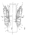
- FIG. 1 therein is shown a chipping head 1 according to the invention installed in a chipping canter.
- the number of chipping heads 1, 1' is two forming a gap through which a wooden workpiece 6 to be processed, such as a log or cant, is fed.
- the opposite sides of the wooden workpiece are worked and chipped by a chipping canter into flat surfaces P, P', whereupon the actual sawing of the log or cant is carried out.
- the chipping heads 1, 1' are rotated on a shaft 10, 10' by a suitable drive means such as an electric motor (not shown in diagrams).
- the chipping head 1, 1' particularly the chipping head of a chipping canter, comprises a head body 2, 2' having thereon adapted multiple chipping knives 3, 3' adapted on the head body circumferentially displaced at a distance from each other.
- the groove 8 and/or ridge 9 made on the chipping head wind(s) from the outer periphery toward the inner periphery, most advantageously in a direction counter to the direction D of chipping head rotation.
- multiple grooves 8 and/or ridges 9 are employed, they form a multiple-ended thread.
- the groove and/or ridge winds about the axis 10 of chipping head rotation by an angle ⁇ (alpha). While the angle ⁇ in FIG. 2 is shown to be about 180°, it may as well be selected in a wide range from 10° to 720°, for instance. Hence, the value of angle ⁇ can be varied from a circular segment to a plural number of turns.
- the radial pitch of the grooves 8 and/or ridges 9 is adapted to comply with the rotating speed of the chipping head 1 and/or the disc-like or flange-like element such as a circular saw blade 4, as well as the desired infeed speed of the wooden workpiece 6 being processed.
- the grooves 8 and/or ridges 9 form on the circular saw blade and/or chipping head 1 a zone 13 that most advantageously has an annular shape.
- the circular saw blade particularly for the chipping head of a chipping canter, has on the lateral surface 7 of the circular saw blade 4 formed at least one groove 8 and/or ridge 9, the groove and/or ridge spiraling about the axis 10 of the circular saw rotation so that the starting point 11 of the groove and/or ridge is radially displaced at a distance from the axis 10 of rotation and, respectively, the end point 12 of the groove/ridge is closer than its starting point 11 to the axis 10 of rotation.
- the groove 8 and/or ridge 9 winds from the outer periphery toward the inner periphery in a direction counter to the direction D of the circular saw rotation. As multiple grooves 8 and/or ridges 9 are employed, they form a multiple-ended thread.
- the radial pitch of grooves 8 and/or ridges 9 is adapted to comply with the rotating speed of the circular saw blade, as well as the desired infeed speed of the wooden workpiece 6 being processed.
- the grooves 8 and/or ridges 9 form on the circular saw blade and/or chipping head 1 a zone 13 that most advantageously has an annular shape.
- the chipping head is generally adapted to rotate in a position tilted from the centerline of the machine by a small angle p thus making the chipping head to "plow" so that in the infeed direction of the log only the trailing area of the chipping head end face meets the wood.
- the end face of chipping head is grooved to reduce the head-to-wood mating area and, hence, the friction therebetween.
- the grooves are made in a spiraling fashion such that the pitch of the spiraling grooves complies with the rotating speed of the chipping head and the average or desired log infeed speed.
- the radial pitch of the spiraling groove may be made such that it matches the travel speed of the log or, moreover, even tending to augment the feed force imposed on the log.
- the grooved annular zone 13 of the chipping head end face is raised outwardly from a given plane of the end face perpendicular to the axis of the chipping head rotation, e.g., from the sawing plane of the circular saw blade touching the wood surface.
- the zone 13 forms the lateral surface of a truncated cone or a portion thereof.
- the inclination angle of the truncated cone relative to the sawing plane typically corresponds to the plowing toe-in angle ⁇ of the chipping head.
- FIG. 3 shows in a cross-sectional view the grooves 8 and/or ridges 9 of the circular saw blade of FIG. 2.
- the depth h of the grooves is in the order of 0.3 - 5 mm, typically 0.5 - 3 mm, most advantageously 0.5 - 1 mm, for instance.
- the shape of the grooves may be varied.
Applications Claiming Priority (2)
| Application Number | Priority Date | Filing Date | Title |
|---|---|---|---|
| FI20030419A FI116208B (fi) | 2003-03-21 | 2003-03-21 | Teräpää |
| FI20030419 | 2003-03-21 |
Publications (2)
| Publication Number | Publication Date |
|---|---|
| EP1459859A2 true EP1459859A2 (de) | 2004-09-22 |
| EP1459859A3 EP1459859A3 (de) | 2007-12-26 |
Family
ID=8565842
Family Applications (1)
| Application Number | Title | Priority Date | Filing Date |
|---|---|---|---|
| EP04075644A Withdrawn EP1459859A3 (de) | 2003-03-21 | 2004-03-02 | Zerspankopf |
Country Status (6)
| Country | Link |
|---|---|
| US (1) | US7210509B2 (de) |
| EP (1) | EP1459859A3 (de) |
| AU (1) | AU2004200831A1 (de) |
| CA (1) | CA2459499A1 (de) |
| FI (1) | FI116208B (de) |
| RU (1) | RU2004108143A (de) |
Cited By (2)
| Publication number | Priority date | Publication date | Assignee | Title |
|---|---|---|---|---|
| EP3354388A1 (de) * | 2017-01-25 | 2018-08-01 | Ledermann GmbH & Co. KG | Zerspanungswerkzeug |
| EP3354387A1 (de) * | 2017-01-25 | 2018-08-01 | Ledermann GmbH & Co. KG | Zerspanungswerkzeug |
Families Citing this family (2)
| Publication number | Priority date | Publication date | Assignee | Title |
|---|---|---|---|---|
| US7441571B2 (en) * | 2005-10-07 | 2008-10-28 | Key Knife, Inc. | Conical chipper/canter head |
| US8225828B2 (en) | 2006-12-11 | 2012-07-24 | Key Knife, Inc. | Modular conical chipper/canter head and method |
Citations (4)
| Publication number | Priority date | Publication date | Assignee | Title |
|---|---|---|---|---|
| US3645308A (en) * | 1968-12-20 | 1972-02-29 | Philip Nilsson | Log-levelling machines |
| US3754297A (en) * | 1972-03-13 | 1973-08-28 | A Metz | Rotary disc cutting device |
| FR2495044A1 (fr) * | 1980-11-29 | 1982-06-04 | Wurster & Dietz Maschf | Outil d'enlevement de copeaux pour machine a bois |
| GB2361884A (en) * | 2000-05-02 | 2001-11-07 | Izard Ind Ltd | Improvement in laser cut saw blades |
Family Cites Families (15)
| Publication number | Priority date | Publication date | Assignee | Title |
|---|---|---|---|---|
| US88649A (en) * | 1869-04-06 | Improvement in index for piling circular saws | ||
| US3165813A (en) * | 1961-06-19 | 1965-01-19 | Rotary Disc File Corp Of Ameri | Rotary file |
| US3330315A (en) * | 1964-05-09 | 1967-07-11 | Dominion Tar & Chemical Co | Log reducer |
| US3732907A (en) * | 1970-06-12 | 1973-05-15 | Pitea Maskin Industri | Device for separating small pieces from a work piece of material |
| DE2158913A1 (de) * | 1971-11-27 | 1973-06-07 | Linck Maschf & Eisen | Werkzeugkopf mit hackmessern und schlichtmessern |
| US3880215A (en) * | 1973-11-21 | 1975-04-29 | Robert Mallery Lumber Corp | Wood chipping apparatus |
| JPS5314498A (en) * | 1976-06-28 | 1978-02-09 | Toyo Pulp Co Ltd | Lumber cutting machine |
| US4187754A (en) * | 1978-09-21 | 1980-02-12 | Beaty Loma B | Noise dampened rotary saw blade |
| FI802468A (fi) * | 1980-08-06 | 1982-02-07 | Kauko Rautio | Skaer foer sparrbilningsmaskin |
| FI69981C (fi) | 1983-01-21 | 1986-09-12 | Martti Vuollet | Hugg |
| SE504417C2 (sv) * | 1995-06-14 | 1997-02-03 | Disc Knife System I Sverige Ab | Blockformningsanordning |
| MD980144A (ro) * | 1995-10-12 | 1999-12-31 | GEBELIUS, Hjordis, Florence, Maria | Procedeu de prevenire sau reducere a magnetizării a două ferestraie-disc adiacente, ce se rotesc în direcţii opuse, şi dispozitiv de realizare a acestui procedeu |
| DE19607558C1 (de) | 1996-02-29 | 1997-05-28 | Manfred Berthold | Vorrichtung zum Ablängen von Holz |
| ATE254016T1 (de) * | 1997-11-04 | 2003-11-15 | Holzindustrie Preding Ges M B | Vorrichtung zur herstellung von kantholz aus rundhölzern |
| FI114294B (fi) | 2000-04-28 | 2004-09-30 | Heinolan Sahakoneet Oy | Pelkkahakkurin teräpää |
-
2003
- 2003-03-21 FI FI20030419A patent/FI116208B/fi active IP Right Grant
-
2004
- 2004-03-02 EP EP04075644A patent/EP1459859A3/de not_active Withdrawn
- 2004-03-03 AU AU2004200831A patent/AU2004200831A1/en not_active Abandoned
- 2004-03-04 CA CA002459499A patent/CA2459499A1/en not_active Abandoned
- 2004-03-19 US US10/804,887 patent/US7210509B2/en active Active
- 2004-03-19 RU RU2004108143/02A patent/RU2004108143A/ru not_active Application Discontinuation
Patent Citations (4)
| Publication number | Priority date | Publication date | Assignee | Title |
|---|---|---|---|---|
| US3645308A (en) * | 1968-12-20 | 1972-02-29 | Philip Nilsson | Log-levelling machines |
| US3754297A (en) * | 1972-03-13 | 1973-08-28 | A Metz | Rotary disc cutting device |
| FR2495044A1 (fr) * | 1980-11-29 | 1982-06-04 | Wurster & Dietz Maschf | Outil d'enlevement de copeaux pour machine a bois |
| GB2361884A (en) * | 2000-05-02 | 2001-11-07 | Izard Ind Ltd | Improvement in laser cut saw blades |
Cited By (2)
| Publication number | Priority date | Publication date | Assignee | Title |
|---|---|---|---|---|
| EP3354388A1 (de) * | 2017-01-25 | 2018-08-01 | Ledermann GmbH & Co. KG | Zerspanungswerkzeug |
| EP3354387A1 (de) * | 2017-01-25 | 2018-08-01 | Ledermann GmbH & Co. KG | Zerspanungswerkzeug |
Also Published As
| Publication number | Publication date |
|---|---|
| AU2004200831A1 (en) | 2004-10-07 |
| US7210509B2 (en) | 2007-05-01 |
| FI20030419A (fi) | 2004-09-22 |
| EP1459859A3 (de) | 2007-12-26 |
| CA2459499A1 (en) | 2004-09-21 |
| RU2004108143A (ru) | 2005-09-27 |
| FI116208B (fi) | 2005-10-14 |
| US20040250898A1 (en) | 2004-12-16 |
| FI20030419A0 (fi) | 2003-03-21 |
Similar Documents
| Publication | Publication Date | Title |
|---|---|---|
| US4266584A (en) | Edger saw combining chipper with circular saw blade | |
| US7210509B2 (en) | Chipping head | |
| EP0478697B1 (de) | Gebüschschneideblatt | |
| US8082958B2 (en) | Knives and knife assemblies | |
| US6505537B1 (en) | Cutting tool and cutting edge configuration thereof | |
| EP3380288B1 (de) | Vorrichtung und verfahren zur verarbeitung von baumstämmen | |
| FI103772B (fi) | Teräpala puuntyöstökonetta varten | |
| US20060208120A1 (en) | Chipper knife | |
| US8281826B2 (en) | Sharp edged knife stop | |
| US5782278A (en) | Cant forming device | |
| EP1513659B1 (de) | Zerspanungsmesser | |
| US3414029A (en) | Knife for cutting lumber | |
| FI70168B (fi) | Foerprofilflishuggare avsett fraeshuvud | |
| EP2035197B1 (de) | Zerspanungswerkzeug zum bearbeiten von plattenkanten, sowie verfahren und vorrichtung zu dessen verwendung | |
| EP3737542B1 (de) | Kreissägeblatt | |
| US3750726A (en) | Chipping knives for chipping head assemblies | |
| EP1276595B1 (de) | Schneidkopf für profilzerspannfräswerkzeug | |
| EP1458531B1 (de) | Verfahren zur planbearbeitung von rundholz | |
| CA1319585C (en) | Brush cutting blade | |
| CA1142063A (en) | Edger saw combining chipper with circular saw blade |
Legal Events
| Date | Code | Title | Description |
|---|---|---|---|
| PUAI | Public reference made under article 153(3) epc to a published international application that has entered the european phase |
Free format text: ORIGINAL CODE: 0009012 |
|
| AK | Designated contracting states |
Kind code of ref document: A2 Designated state(s): AT BE BG CH CY CZ DE DK EE ES FI FR GB GR HU IE IT LI LU MC NL PL PT RO SE SI SK TR |
|
| AX | Request for extension of the european patent |
Extension state: AL HR LT LV MK |
|
| PUAL | Search report despatched |
Free format text: ORIGINAL CODE: 0009013 |
|
| AK | Designated contracting states |
Kind code of ref document: A3 Designated state(s): AT BE BG CH CY CZ DE DK EE ES FI FR GB GR HU IE IT LI LU MC NL PL PT RO SE SI SK TR |
|
| AX | Request for extension of the european patent |
Extension state: AL LT LV MK |
|
| 17P | Request for examination filed |
Effective date: 20080201 |
|
| 17Q | First examination report despatched |
Effective date: 20080507 |
|
| AKX | Designation fees paid |
Designated state(s): AT BE BG CH CY CZ DE DK EE ES FI FR GB GR HU IE IT LI LU MC NL PL PT RO SE SI SK TR |
|
| STAA | Information on the status of an ep patent application or granted ep patent |
Free format text: STATUS: THE APPLICATION IS DEEMED TO BE WITHDRAWN |
|
| 18D | Application deemed to be withdrawn |
Effective date: 20080918 |