EP1459725A1 - Apparatus for and method of sealing capsules - Google Patents
Apparatus for and method of sealing capsules Download PDFInfo
- Publication number
- EP1459725A1 EP1459725A1 EP03290723A EP03290723A EP1459725A1 EP 1459725 A1 EP1459725 A1 EP 1459725A1 EP 03290723 A EP03290723 A EP 03290723A EP 03290723 A EP03290723 A EP 03290723A EP 1459725 A1 EP1459725 A1 EP 1459725A1
- Authority
- EP
- European Patent Office
- Prior art keywords
- sealing
- capsule
- clamp
- overlap
- sealing clamp
- Prior art date
- Legal status (The legal status is an assumption and is not a legal conclusion. Google has not performed a legal analysis and makes no representation as to the accuracy of the status listed.)
- Granted
Links
Images



Classifications
-
- A—HUMAN NECESSITIES
- A61—MEDICAL OR VETERINARY SCIENCE; HYGIENE
- A61J—CONTAINERS SPECIALLY ADAPTED FOR MEDICAL OR PHARMACEUTICAL PURPOSES; DEVICES OR METHODS SPECIALLY ADAPTED FOR BRINGING PHARMACEUTICAL PRODUCTS INTO PARTICULAR PHYSICAL OR ADMINISTERING FORMS; DEVICES FOR ADMINISTERING FOOD OR MEDICINES ORALLY; BABY COMFORTERS; DEVICES FOR RECEIVING SPITTLE
- A61J3/00—Devices or methods specially adapted for bringing pharmaceutical products into particular physical or administering forms
- A61J3/07—Devices or methods specially adapted for bringing pharmaceutical products into particular physical or administering forms into the form of capsules or similar small containers for oral use
- A61J3/071—Devices or methods specially adapted for bringing pharmaceutical products into particular physical or administering forms into the form of capsules or similar small containers for oral use into the form of telescopically engaged two-piece capsules
- A61J3/072—Sealing capsules, e.g. rendering them tamper-proof
Definitions
- This invention relates to a method of and apparatus for sealing capsules and to the capsule formed thereby.
- the capsules sealed by the method and apparatus according to the present invention are hard shell, telescopically joined capsules with coaxial partly overlapping body parts.
- the capsules may be made of gelatin or of other materials whose properties are pharmaceutically acceptable with respect to their chemical and physical properties.
- EP 0 116 743 A1, EP 0 116 744 A1 and EP 0 180 543 A1 disclose methods and devices for sealing such capsules having hard shell coaxial cap and body parts which overlap when telescopically joined.
- the process employed comprises the steps of dipping batches of the capsules randomly oriented in mesh baskets or oriented with their cap parts upright into a sealing fluid making capillary action within the overlap of the cap and body parts or spraying the sealing fluid or steam thereof onto the seam of the overlap, removing the sealing fluid from the surface of the capsules by an air blower, and applying thermal energy to the capsules while conveying the baskets through a dryer.
- the documents disclose the use of a wide range of sealing fluids and specific temperatures and modes of application of thermal energy, the disclosure of which is incorporated herein by reference.
- EP 1 072 245 A1 also discloses a method for sealing telescopically joined capsules with coaxial body parts through subsequent application of a sealing liquid by the overlapping region at the joint between a cap and a body, the removal of excess sealing liquid, and the application of thermal energy for drying purposes.
- This document particularly describes the steps of applying a sealing liquid including a solvent uniformly to the external edge of the gap of a capsule to be sealed to form a liquid ring around the circumference of the capsule, removing excess sealing liquid from the exterior of the capsule and drying the capsule by applying thermal energy from outside while gently tumbling and conveying the capsule on a spiral path.
- Spray nozzles are used for individually applying the sealing liquid.
- the excess solution is removed from around the capsule by vacuum suction or air jets.
- the present invention aims at providing an improved method and apparatus for sealing telescopically joined capsules with coaxial partly overlapping body parts, through subsequent application of a sealing fluid and an improvement of the fluid injection phase in order to reach the maximum volume available in the overlap of the body parts while the capsule remains free of residual liquid on its surface.
- the present invention provides a method and an apparatus for sealing telecopically joined capsules with coaxial partly overlapping body parts as defined in the appended claims.
- Sealing clamps are used to seal efficiently hard capsules. Filled or empty capsules are to be oriented before the sealing operation. The sealing clamps hold each capsule in a precise and reproducible upright position.
- a known quantity of sealing fluid is injected in the overlap of the body parts within a well-defined volume. The excess of sealing fluid is removed from the outside of the capsule shell. Moreover the excess of sealing fluid is removed from the sealing clamp to prevent build-up of sealing fluid. Finally the capsule is released properly.
- Using a spray clamp also forces the capsules to be cylindrical which is an advantage when using flexible polymer material to manufacture capsule.
- the capsule diameter is homogeneous on 360°.
- the penetration of the sealing liquid by the capillary effect on the whole capsule circumference is favoured.
- An additional benefit to use a sealing clamp is to guarantee an actual vertical positioning of the capsule with regard to the location of the sealing liquid injection hole.
- the spray clamp can be composed of different parts. Each part will participate to the various steps of the process. As an example, the injection of the sealing liquid can happen in one part whilst the excess of sealing fluid can be collected in a second part.
- the number of main functional parts that compose the spray clamp can vary from one to six.
- the number of injection ports can vary from one to eight.
- the number of suction ports can vary from one to ten.
- the number of airing can vary from one to six.
- the positioning of those parts can be spatially arranged to obtain the desired effect.
- One to three liquid recovery grooves can be added to the design of clamp.
- the sealing clamp consists of two parts. These two parts are joined together to open and close the sealing clamp.
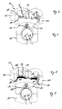
- Figure 1 and 2 show a first embodiment of a sealing clamp 1 consisting of a first part 2 and a second part 3.
- a sealing clamp 1 consisting of a first part 2 and a second part 3.
- the sealing fluid is injected via an injection port 5 located at 90° from the parting line of the first part 2.
- Air or any other gas can flow through an airing 6 located at 45° from the parting line of the first part 2 and two suction ports 7 located at 90° and 60° from the parting line of the second part 3.
- the injection port 5 and the airing 6 are located between 0 and 2 mm below the cap edge while the two suction ports 7 are in the liquid recovery groove 8.
- the difference between the first embodiment of a sealing clamp in figure 1 and 2 and the other embodiments shown in figure 3 to 14 consists in the number and position of injection ports 5, airings 6, suction ports 7 and liquid recovery grooves 8.
- the embodiments one to four of figures 1 to 8 enable sealing of 20 to 50 % of the maximum surface available. With the sealing clamp of embodiment five a sealed surface of 80 % is reached. Use of the sealing clamp of embodiment six gives a large sealed zone of 90 to 100 %. With the sealing clamp of embodiment seven the total removal of the excess of sealing fluid from the capsule shell is possible preventing subsequent process defects.
- a second embodiment of a sealing clamp 11 shown in figure 3 and 4 consists of a first part 12 and a second part 13.
- the edge of the cap of a capsule is precisely located between 0 and 2 mm above the injection port 15.
- the sealing fluid is injected via an injection port 15 located at 90° from the parting line of the first part 12.
- Air or any other gas can flow through an airing 16 located at 75° from the parting line of the first part 12 and two suction ports 17 located at 90° and 60° from the parting line of the second part 13.
- the injection port 15 is located between 0 and 2 mm below the edge of the cap of a capsule while the airing 16 and the two suction ports 17 are in the liquid recovery groove 18.
- a third embodiment of a sealing clamp 21 shown in figure 5 and 6 consists of a first part 22 and a second part 23.
- the edge of the cap of a capsule, not shown in the drawings, is at the bottom 29 of the liquid recovery groove 28.
- the sealing fluid is injected via an injection port 25 located at 90° from the parting line of the first part 22 in the liquid recovery groove 28.
- Air or any other gas can flow through an airing 26 located at 45° from the parting line of the first part 22 and two suction ports 27 located at 90° and 60° from the parting line of the second part 23.
- the airing 26 and the two suction ports 27 are located in the liquid recovery groove 28.
- a forth embodiment of a sealing clamp 31 shown in figure 7 and 8 consists of a first part 32 and a second part 33.
- the sealing fluid is injected via an injection port 35 located at 90° from the parting line of the first part 32 in the liquid recovery groove 38.
- Air or any other gas can flow through an airing 36 located at 45° from the parting line of the first part 32 and two suction ports 37 located at 90° and 60° from the parting line of the second part 33.
- the airing 36 and the two suction ports 37 are located in the liquid recovery groove 38.
- Additional features are an absorbent layer 39 and a vertical rubber coating 40 at the bottom of the sealing clamp 31.
- a fifth embodiment of a sealing clamp 41 shown in figure 9 and 10 consists of a first part 42 and a second part 43.
- the edge of the cap of a capsule, not shown in the drawings, is at the bottom 50 of a liquid injection groove 49 of the sealing clamp 41.
- the sealing fluid is injected via two injection ports 45 located at 60° from the parting line of the first part 42 and at 60° from the parting line of the second part 43. Both injection ports 45 enter into a liquid injection groove 49.
- Air or any other gas can flow through two airings 46 located at 30° from the parting line of the first part 42 and of the second part 43 and through four suction ports 47 located at 90° and 120° from the parting line of the first part 42 and of the second part 43.
- the airings 46 and the suction ports 47 are located in the liquid recovery groove 48.
- a sixth embodiment of a sealing clamp 51 shown in figure 11 and 12 consists of a first part 52 and a second part 53.
- the edge of the cap of a capsule, not shown in the drawings, is precisely located between 0 and 2 mm above the injection port 55.
- the sealing fluid is injected via an injection port 55 located at 60° from the parting line of the first part 52.
- Air or any other gas can flow through an airing 56 located at 90° from the parting line of the first part 52 and a suction port 57 located at 120° from the parting line of the second part 53.
- the airing 56 and the suction port 57 are in the liquid recovery groove 58.
- a seventh embodiment of a sealing clamp 61 shown in figure 13 and 14 consists of a first part 62 and a second part 63.
- the edge of the cap of a capsule is at the bottom 70 of a liquid injection groove 69 of the sealing clamp 61.
- the sealing fluid is injected via two injection ports 65 located at 135° from the parting line of the first part 62 and at 135° from the parting line of the second part 63. Both injection ports 65 enter into a liquid injection groove 69.
- Air or any other gas can flow through two airings 66 located at 150° from the parting line of the first part 62 and of the second part 63 and through four suction ports 67 located at 30° and 60° from the parting line of the first part 62 and of the second part 63.
- the airings 66 and the suction ports 67 are located in the liquid recovery groove 68.
Landscapes
- Health & Medical Sciences (AREA)
- General Health & Medical Sciences (AREA)
- Medicinal Chemistry (AREA)
- Pharmacology & Pharmacy (AREA)
- Life Sciences & Earth Sciences (AREA)
- Animal Behavior & Ethology (AREA)
- Chemical & Material Sciences (AREA)
- Public Health (AREA)
- Veterinary Medicine (AREA)
- Medical Preparation Storing Or Oral Administration Devices (AREA)
- Closing Of Containers (AREA)
- Infusion, Injection, And Reservoir Apparatuses (AREA)
- Filling Of Jars Or Cans And Processes For Cleaning And Sealing Jars (AREA)
Abstract
Description
- This invention relates to a method of and apparatus for sealing capsules and to the capsule formed thereby.
- The capsules sealed by the method and apparatus according to the present invention are hard shell, telescopically joined capsules with coaxial partly overlapping body parts. The capsules may be made of gelatin or of other materials whose properties are pharmaceutically acceptable with respect to their chemical and physical properties.
- The problem to be solved with respect to such capsules as compared to other dosage forms is the fact that the coaxial body parts must be well sealed in order to avoid leaking of any content to the outside or contamination thereof. Further, tampering with the content of the capsule or the capsule as such should be evident and externally visible for safety proposes. Any technique of sealing the capsules must be suitable for large scale bulk production to reduce manufacturing time and costs and to reduce waste due to imperfections of the product.
- EP 0 116 743 A1, EP 0 116 744 A1 and EP 0 180 543 A1 disclose methods and devices for sealing such capsules having hard shell coaxial cap and body parts which overlap when telescopically joined. The process employed comprises the steps of dipping batches of the capsules randomly oriented in mesh baskets or oriented with their cap parts upright into a sealing fluid making capillary action within the overlap of the cap and body parts or spraying the sealing fluid or steam thereof onto the seam of the overlap, removing the sealing fluid from the surface of the capsules by an air blower, and applying thermal energy to the capsules while conveying the baskets through a dryer. The documents disclose the use of a wide range of sealing fluids and specific temperatures and modes of application of thermal energy, the disclosure of which is incorporated herein by reference.
- EP 1 072 245 A1 also discloses a method for sealing telescopically joined capsules with coaxial body parts through subsequent application of a sealing liquid by the overlapping region at the joint between a cap and a body, the removal of excess sealing liquid, and the application of thermal energy for drying purposes. This document particularly describes the steps of applying a sealing liquid including a solvent uniformly to the external edge of the gap of a capsule to be sealed to form a liquid ring around the circumference of the capsule, removing excess sealing liquid from the exterior of the capsule and drying the capsule by applying thermal energy from outside while gently tumbling and conveying the capsule on a spiral path. Spray nozzles are used for individually applying the sealing liquid. The excess solution is removed from around the capsule by vacuum suction or air jets. The disclosure of this document is incorporated herein by reference, too.
- The prior systems for sealing capsules are partly imperfect as regards the quality of the seal and the controllability of the process parameters influencing the quality of the seal.
- The present invention aims at providing an improved method and apparatus for sealing telescopically joined capsules with coaxial partly overlapping body parts, through subsequent application of a sealing fluid and an improvement of the fluid injection phase in order to reach the maximum volume available in the overlap of the body parts while the capsule remains free of residual liquid on its surface.
- With respect to this object the present invention provides a method and an apparatus for sealing telecopically joined capsules with coaxial partly overlapping body parts as defined in the appended claims. Sealing clamps are used to seal efficiently hard capsules. Filled or empty capsules are to be oriented before the sealing operation. The sealing clamps hold each capsule in a precise and reproducible upright position. A known quantity of sealing fluid is injected in the overlap of the body parts within a well-defined volume. The excess of sealing fluid is removed from the outside of the capsule shell. Moreover the excess of sealing fluid is removed from the sealing clamp to prevent build-up of sealing fluid. Finally the capsule is released properly.
- The use of spray clamps instead of bushings or any other apparatus enables to limit the zone where the sealing fluid is injected to the overlap of the body parts. The design of the sealing clamp limits the location of the sealing fluid to the interior volume of the clamp. The excess of sealing fluid remaining in the clamp is recovered through suction channels.
- Using a spray clamp also forces the capsules to be cylindrical which is an advantage when using flexible polymer material to manufacture capsule. Thus the capsule diameter is homogeneous on 360°. The penetration of the sealing liquid by the capillary effect on the whole capsule circumference is favoured. An additional benefit to use a sealing clamp is to guarantee an actual vertical positioning of the capsule with regard to the location of the sealing liquid injection hole.
- The spray clamp can be composed of different parts. Each part will participate to the various steps of the process. As an example, the injection of the sealing liquid can happen in one part whilst the excess of sealing fluid can be collected in a second part.
- The number of main functional parts that compose the spray clamp can vary from one to six. The number of injection ports can vary from one to eight. The number of suction ports can vary from one to ten. The number of airing can vary from one to six. The positioning of those parts can be spatially arranged to obtain the desired effect. One to three liquid recovery grooves can be added to the design of clamp.
- In a preferred embodiment the sealing clamp consists of two parts. These two parts are joined together to open and close the sealing clamp.
- The present invention will now be described in more detail, by way of example, with reference to the accompanying drawings in which the following figures show:
- Fig. 1
- first embodiment of a sealing clamp in open position in perspective view,
- Fig. 2
- sealing clamp of Fig. 1, closed, in cross section,
- Fig. 3
- second embodiment of a sealing clamp in open position in perspective view,
- Fig. 4
- sealing clamp of Fig. 3, closed, in cross section,
- Fig. 5
- third embodiment of a sealing clamp in open position in perspective view,
- Fig. 6
- sealing clamp of Fig. 5, closed, in cross section,
- Fig. 7
- forth embodiment of a sealing clamp in open position in perspective view,
- Fig. 8
- sealing clamp of Fig. 7, closed, in cross section,
- Fig. 9
- fifth embodiment of a sealing clamp in open position in perspective view,
- Fig. 10
- sealing clamp of Fig. 9, closed, in cross section,
- Fig. 11
- sixth embodiment of a sealing clamp in open position in perspective view,
- Fig. 12
- sealing clamp of Fig. 11, closed, in cross section,
- Fig. 13
- seventh embodiment of a sealing clamp in open position in perspective view,
- Fig. 14
- sealing clamp of Fig. 13, closed, in cross section.
- Figure 1 and 2 show a first embodiment of a sealing clamp 1 consisting of a
first part 2 and asecond part 3. In the closed sealing clamp the edge of the cap of a capsule, not shown in the drawings, is precisely located between 0 and 2 mm above the injection port 5. The sealing fluid is injected via an injection port 5 located at 90° from the parting line of thefirst part 2. Air or any other gas can flow through anairing 6 located at 45° from the parting line of thefirst part 2 and two suction ports 7 located at 90° and 60° from the parting line of thesecond part 3. The injection port 5 and theairing 6 are located between 0 and 2 mm below the cap edge while the two suction ports 7 are in the liquid recovery groove 8. - The difference between the first embodiment of a sealing clamp in figure 1 and 2 and the other embodiments shown in figure 3 to 14 consists in the number and position of injection ports 5,
airings 6, suction ports 7 and liquid recovery grooves 8. The embodiments one to four of figures 1 to 8 enable sealing of 20 to 50 % of the maximum surface available. With the sealing clamp of embodiment five a sealed surface of 80 % is reached. Use of the sealing clamp of embodiment six gives a large sealed zone of 90 to 100 %. With the sealing clamp of embodiment seven the total removal of the excess of sealing fluid from the capsule shell is possible preventing subsequent process defects. - A second embodiment of a sealing clamp 11 shown in figure 3 and 4 consists of a
first part 12 and asecond part 13. In the closed sealing clamp the edge of the cap of a capsule, not shown in the drawings, is precisely located between 0 and 2 mm above theinjection port 15. The sealing fluid is injected via aninjection port 15 located at 90° from the parting line of thefirst part 12. Air or any other gas can flow through an airing 16 located at 75° from the parting line of thefirst part 12 and twosuction ports 17 located at 90° and 60° from the parting line of thesecond part 13. Theinjection port 15 is located between 0 and 2 mm below the edge of the cap of a capsule while the airing 16 and the twosuction ports 17 are in theliquid recovery groove 18. - A third embodiment of a sealing
clamp 21 shown in figure 5 and 6 consists of afirst part 22 and asecond part 23. In the closed sealing clamp the edge of the cap of a capsule, not shown in the drawings, is at the bottom 29 of theliquid recovery groove 28. The sealing fluid is injected via aninjection port 25 located at 90° from the parting line of thefirst part 22 in theliquid recovery groove 28. Air or any other gas can flow through an airing 26 located at 45° from the parting line of thefirst part 22 and two suction ports 27 located at 90° and 60° from the parting line of thesecond part 23. The airing 26 and the two suction ports 27 are located in theliquid recovery groove 28. - A forth embodiment of a sealing
clamp 31 shown in figure 7 and 8 consists of afirst part 32 and asecond part 33. In the closed sealing clamp the edge of the cap of a capsule, not shown in the drawings, is at the bottom 34 of the liquid recovery groove 38. The sealing fluid is injected via aninjection port 35 located at 90° from the parting line of thefirst part 32 in the liquid recovery groove 38. Air or any other gas can flow through an airing 36 located at 45° from the parting line of thefirst part 32 and two suction ports 37 located at 90° and 60° from the parting line of thesecond part 33. The airing 36 and the two suction ports 37 are located in the liquid recovery groove 38. Additional features are anabsorbent layer 39 and a vertical rubber coating 40 at the bottom of the sealingclamp 31. - A fifth embodiment of a sealing clamp 41 shown in figure 9 and 10 consists of a
first part 42 and asecond part 43. In the closed sealing clamp the edge of the cap of a capsule, not shown in the drawings, is at the bottom 50 of a liquid injection groove 49 of the sealing clamp 41. The sealing fluid is injected via twoinjection ports 45 located at 60° from the parting line of thefirst part 42 and at 60° from the parting line of thesecond part 43. Bothinjection ports 45 enter into a liquid injection groove 49. Air or any other gas can flow through twoairings 46 located at 30° from the parting line of thefirst part 42 and of thesecond part 43 and through four suction ports 47 located at 90° and 120° from the parting line of thefirst part 42 and of thesecond part 43. Theairings 46 and the suction ports 47 are located in theliquid recovery groove 48. - A sixth embodiment of a sealing clamp 51 shown in figure 11 and 12 consists of a
first part 52 and asecond part 53. In the closed sealing clamp the edge of the cap of a capsule, not shown in the drawings, is precisely located between 0 and 2 mm above theinjection port 55. The sealing fluid is injected via aninjection port 55 located at 60° from the parting line of thefirst part 52. Air or any other gas can flow through an airing 56 located at 90° from the parting line of thefirst part 52 and a suction port 57 located at 120° from the parting line of thesecond part 53. The airing 56 and the suction port 57 are in theliquid recovery groove 58. - A seventh embodiment of a sealing clamp 61 shown in figure 13 and 14 consists of a first part 62 and a
second part 63. In the closed sealing clamp the edge of the cap of a capsule, not shown in the drawings, is at the bottom 70 of aliquid injection groove 69 of the sealing clamp 61. The sealing fluid is injected via twoinjection ports 65 located at 135° from the parting line of the first part 62 and at 135° from the parting line of thesecond part 63. Bothinjection ports 65 enter into aliquid injection groove 69. Air or any other gas can flow through twoairings 66 located at 150° from the parting line of the first part 62 and of thesecond part 63 and through foursuction ports 67 located at 30° and 60° from the parting line of the first part 62 and of thesecond part 63. Theairings 66 and thesuction ports 67 are located in theliquid recovery groove 68.
Claims (8)
- A method of sealing a hard shell capsule having coaxial body parts which overlap when telescopically joined, which method comprises the steps of
holding the capsule in a precise and upright position,
injecting a known quantity of sealing fluid in the overlap of the body parts, releasing the capsule. - Method according to claim 1, characterised in that the excess of sealing fluid is removed from the outside of the capsule shell.
- Method according to claim 1 or 2, characterised in that the excess of sealing fluid is removed from a clamp holding the capsule in the upright position.
- An apparatus for sealing a hard shell capsule having coaxial body parts which overlap when telescopically joined, the apparatus comprising
a sealing clamp (1, 11, 21, 31, 41, 51, 61) to hold the capsule in an upright position and
means (5, 15, 25, 35, 45, 55, 65) to inject the sealing fluid in the overlap of cap and body part. - An apparatus according to claim 4, characterised in that the means to inject the sealing fluid are injection ports (5, 15, 25, 35, 45, 55, 65) in the sealing clamp (1, 11, 21, 31, 41, 51, 61).
- An apparatus according to claim 4, characterised in that the sealing clamp has liquid recovery grooves (8, 18, 28, 38, 48, 58, 68).
- An apparatus according to claim 4, characterised in that the sealing clamp has airing (6, 16, 26, 36, 46, 56, 66) and suction ports (7, 17, 27, 37, 47, 57,67).
- An apparatus according to claim 4, characterised in that the sealing clamp has a liquid injection groove (49, 69).
Priority Applications (20)
| Application Number | Priority Date | Filing Date | Title |
|---|---|---|---|
| EP03290723A EP1459725B1 (en) | 2003-03-21 | 2003-03-21 | Apparatus for and method of sealing capsules |
| US10/795,898 US7645407B2 (en) | 2003-03-21 | 2004-03-08 | Method of sealing a hard shell capsule |
| MXPA05010013A MXPA05010013A (en) | 2003-03-21 | 2004-03-10 | Apparatus for and method of sealing capsules. |
| PL04719027T PL1617800T3 (en) | 2003-03-21 | 2004-03-10 | Apparatus for and method of sealing capsules |
| JP2006500340A JP4597120B2 (en) | 2003-03-21 | 2004-03-10 | Apparatus and method for sealing capsules |
| ES04719027T ES2343801T3 (en) | 2003-03-21 | 2004-03-10 | APPLIANCE AND PROCEDURE TO SEAL CAPSULES. |
| SI200431455T SI1617800T1 (en) | 2003-03-21 | 2004-03-10 | Apparatus for and method of sealing capsules |
| CNB200480007489XA CN100482197C (en) | 2003-03-21 | 2004-03-10 | Apparatus for and method of sealing capsules |
| EP04719027A EP1617800B1 (en) | 2003-03-21 | 2004-03-10 | Apparatus for and method of sealing capsules |
| BRPI0408612-0A BRPI0408612B1 (en) | 2003-03-21 | 2004-03-10 | APPLIANCE FOR AND CAPSULES SEALING METHOD |
| AU2004222469A AU2004222469B2 (en) | 2003-03-21 | 2004-03-10 | Apparatus for and method of sealing capsules |
| EA200501369A EA007670B1 (en) | 2003-03-21 | 2004-03-10 | Apparatus for and method of sealing capsules |
| PCT/IB2004/000862 WO2004082563A1 (en) | 2003-03-21 | 2004-03-10 | Apparatus for and method of sealing capsules |
| DE602004027364T DE602004027364D1 (en) | 2003-03-21 | 2004-03-10 | DEVICE AND METHOD FOR SEALING CAPSULES |
| PT04719027T PT1617800E (en) | 2003-03-21 | 2004-03-10 | Apparatus for and method of sealing capsules |
| CA002514246A CA2514246C (en) | 2003-03-21 | 2004-03-10 | Apparatus for and method of sealing capsules |
| AT04719027T ATE468837T1 (en) | 2003-03-21 | 2004-03-10 | DEVICE AND METHOD FOR SEALING CAPSULES |
| KR1020057017538A KR101012924B1 (en) | 2003-03-21 | 2004-03-10 | Hard shell capsule sealing method and device |
| US12/563,510 US20100009027A1 (en) | 2003-03-21 | 2009-09-21 | Apparatus for and method of sealing capsules |
| US13/166,035 US8491298B2 (en) | 2003-03-21 | 2011-06-22 | Apparatus for sealing a pharmaceutically acceptable hard shell capsule |
Applications Claiming Priority (1)
| Application Number | Priority Date | Filing Date | Title |
|---|---|---|---|
| EP03290723A EP1459725B1 (en) | 2003-03-21 | 2003-03-21 | Apparatus for and method of sealing capsules |
Publications (2)
| Publication Number | Publication Date |
|---|---|
| EP1459725A1 true EP1459725A1 (en) | 2004-09-22 |
| EP1459725B1 EP1459725B1 (en) | 2007-10-17 |
Family
ID=32799138
Family Applications (2)
| Application Number | Title | Priority Date | Filing Date |
|---|---|---|---|
| EP03290723A Expired - Lifetime EP1459725B1 (en) | 2003-03-21 | 2003-03-21 | Apparatus for and method of sealing capsules |
| EP04719027A Expired - Lifetime EP1617800B1 (en) | 2003-03-21 | 2004-03-10 | Apparatus for and method of sealing capsules |
Family Applications After (1)
| Application Number | Title | Priority Date | Filing Date |
|---|---|---|---|
| EP04719027A Expired - Lifetime EP1617800B1 (en) | 2003-03-21 | 2004-03-10 | Apparatus for and method of sealing capsules |
Country Status (17)
| Country | Link |
|---|---|
| US (3) | US7645407B2 (en) |
| EP (2) | EP1459725B1 (en) |
| JP (1) | JP4597120B2 (en) |
| KR (1) | KR101012924B1 (en) |
| CN (1) | CN100482197C (en) |
| AT (1) | ATE468837T1 (en) |
| AU (1) | AU2004222469B2 (en) |
| BR (1) | BRPI0408612B1 (en) |
| CA (1) | CA2514246C (en) |
| DE (1) | DE602004027364D1 (en) |
| EA (1) | EA007670B1 (en) |
| ES (1) | ES2343801T3 (en) |
| MX (1) | MXPA05010013A (en) |
| PL (1) | PL1617800T3 (en) |
| PT (1) | PT1617800E (en) |
| SI (1) | SI1617800T1 (en) |
| WO (1) | WO2004082563A1 (en) |
Cited By (4)
| Publication number | Priority date | Publication date | Assignee | Title |
|---|---|---|---|---|
| WO2008015519A1 (en) * | 2006-08-04 | 2008-02-07 | Pfizer Products Inc. | Method and apparatus for sealing capsules |
| US9340004B2 (en) | 2011-10-06 | 2016-05-17 | Bio Capsule Pharmaceutical And Nutritional Products (Pty) Ltd. | Method and apparatus for manufacturing a capsule |
| US9456987B2 (en) | 2013-04-03 | 2016-10-04 | Binutra, Inc. | Capsule with internal diaphragm |
| EP3219300A1 (en) | 2016-03-15 | 2017-09-20 | Capsugel Belgium NV | Aseptic hard capsule sealing apparatus and methods |
Families Citing this family (8)
| Publication number | Priority date | Publication date | Assignee | Title |
|---|---|---|---|---|
| KR100624651B1 (en) * | 2002-06-18 | 2006-09-19 | 가부시키가이샤 아마다 | Die and die device |
| US8810259B2 (en) * | 2009-11-13 | 2014-08-19 | Capsugel Belgium Nv | Method of inspection of sealed capsules with a process of determination of the quality of the seal and related equipment for in-line inspection |
| US20160015647A1 (en) | 2013-03-07 | 2016-01-21 | Capsugel Belgium Nv | Bismuth liquid filled hard capsules |
| CN103565647B (en) * | 2013-10-28 | 2015-06-10 | 刘凯培 | Hollow soft capsule and preparation method thereof |
| EP3065720A1 (en) | 2013-11-04 | 2016-09-14 | Capsugel Belgium NV | Methods and systems for improved bioavailability of active pharmaceutical ingredients including esomeprazole |
| CN108451016B (en) * | 2018-05-29 | 2021-01-29 | 云南中烟工业有限责任公司 | Preparation method of preformed water-containing blasting bead for cigarettes |
| EP3607931B1 (en) * | 2018-08-07 | 2023-03-29 | Harro Höfliger Verpackungsmaschinen GmbH | Capsule closing device for closing two-part capsules |
| EP3861974B1 (en) * | 2020-02-07 | 2023-06-07 | Harro Höfliger Verpackungsmaschinen GmbH | Capsule closing device for closing two-part capsules |
Citations (4)
| Publication number | Priority date | Publication date | Assignee | Title |
|---|---|---|---|---|
| US3025652A (en) * | 1960-08-09 | 1962-03-20 | American Cyanamid Co | Sealing hard shell capsules |
| EP0110603A2 (en) * | 1982-11-23 | 1984-06-13 | Warner-Lambert Company | Apparatus for and method of sealing capsules |
| DE3246392A1 (en) * | 1982-12-15 | 1984-06-20 | Robert Bosch Gmbh, 7000 Stuttgart | Method of manufacturing a fixed connection between the cap and capsule body of an inserted capsule |
| US4940499A (en) * | 1989-05-23 | 1990-07-10 | Warner-Lambert Company | Method and apparatus for sealing capsules containing medicaments |
Family Cites Families (27)
| Publication number | Priority date | Publication date | Assignee | Title |
|---|---|---|---|---|
| US2936493A (en) * | 1955-06-16 | 1960-05-17 | Scherer Corp R P | Method of making plastic capsules |
| US3182110A (en) * | 1958-11-05 | 1965-05-04 | White Consolidated Ind Inc | Method and apparatus for making fiber glass tank |
| DE1221864B (en) * | 1960-11-30 | 1966-07-28 | Langen & Co | Pressure accumulator |
| US3073087A (en) * | 1962-01-25 | 1963-01-15 | American Cyanamid Co | Method of sealing hard shell capsules |
| US3653500A (en) * | 1969-07-11 | 1972-04-04 | Lilly Co Eli | Filled capsules |
| US3671622A (en) * | 1970-11-13 | 1972-06-20 | Bethlehem Steel Corp | Method of forming seal for multi-wire strand |
| BE794882A (en) * | 1972-02-15 | 1973-05-29 | Stewing Albert | CHANNEL SHEATH FOR CABLES AND METHOD FOR ITS REALIZATION |
| US4155478A (en) * | 1975-05-12 | 1979-05-22 | Yoshio Ogi | Plastic articles |
| JPS51135978A (en) * | 1975-05-12 | 1976-11-25 | Yoshio Ogi | Synthetic resin moldings and method of producing same |
| DE2706649A1 (en) * | 1977-02-23 | 1978-08-24 | Pilgrim Eng Dev | PIPE JOINT AND METHOD OF MANUFACTURING THE SAME |
| ES468317A1 (en) * | 1977-03-29 | 1979-08-01 | Capsugel Ag | IMPROVEMENTS INTRODUCED IN A CLOSURE CAPSULE FILLED WITH VISCOSE MATERIAL, IN PARTICULAR A LIQUID PHARMA-CEUTIC PREPARATION. |
| DE2722822C2 (en) * | 1977-05-20 | 1984-11-08 | Capsugel AG, Basel | Method for producing a push-fit capsule suitable for receiving a viscous substance, in particular a liquid medicament |
| US4235832A (en) * | 1978-07-31 | 1980-11-25 | Alden Research Foundation | Molding method |
| US4415387A (en) * | 1980-12-12 | 1983-11-15 | The Continental Group, Inc. | Method of forming an annular seam between two container body halves |
| US4628850A (en) * | 1982-02-25 | 1986-12-16 | Rubber Millers, Inc. | Marine fender |
| EP0116744A1 (en) | 1982-12-20 | 1984-08-29 | Warner-Lambert Company | Apparatus for and method of sealing capsules |
| US4539060A (en) | 1983-02-18 | 1985-09-03 | Warner-Lambert Company | Apparatus and method of sealing capsules |
| EP0135372A3 (en) * | 1983-09-16 | 1986-01-02 | R.P. Scherer Corporation | Gelatin capsule and method and apparatus for ultrasonically welding thereof |
| US4576284A (en) * | 1983-12-02 | 1986-03-18 | Warner-Lambert Company | Closing of filled capsules |
| DE3574673D1 (en) * | 1984-03-12 | 1990-01-18 | Nippon Elanco | DEVICE FOR SEALING CAPSULES. |
| IE58468B1 (en) | 1984-10-25 | 1993-09-22 | Warner Lambert Co | Method for sealing capsules and capsule |
| GB8428750D0 (en) * | 1984-11-14 | 1984-12-27 | Lilly Industries Ltd | Stripper rings |
| CH674800A5 (en) * | 1986-03-12 | 1990-07-31 | Warner Lambert Co | |
| CA2088468C (en) * | 1992-11-16 | 1999-07-27 | David E. Calapp | Composite hockey stick shaft and process for making same |
| EP1072245A1 (en) * | 1999-07-30 | 2001-01-31 | Warner-Lambert Company | Method and apparatus for sealing capsules and capsules suitable for use in said method and apparatus |
| US6284181B1 (en) * | 1999-09-07 | 2001-09-04 | Ivan Gaster | Over-molded product and method of manufacture |
| DE10137054A1 (en) * | 2001-07-28 | 2003-02-13 | Boehringer Ingelheim Pharma | Sealing plastic capsules containing inhalable drug, by welding telescopically fitting capsule parts by applying jet of hot gas or a laser beam to overlapping regions during relative movement |
-
2003
- 2003-03-21 EP EP03290723A patent/EP1459725B1/en not_active Expired - Lifetime
-
2004
- 2004-03-08 US US10/795,898 patent/US7645407B2/en not_active Expired - Lifetime
- 2004-03-10 MX MXPA05010013A patent/MXPA05010013A/en active IP Right Grant
- 2004-03-10 BR BRPI0408612-0A patent/BRPI0408612B1/en not_active IP Right Cessation
- 2004-03-10 EP EP04719027A patent/EP1617800B1/en not_active Expired - Lifetime
- 2004-03-10 PT PT04719027T patent/PT1617800E/en unknown
- 2004-03-10 SI SI200431455T patent/SI1617800T1/en unknown
- 2004-03-10 DE DE602004027364T patent/DE602004027364D1/en not_active Expired - Lifetime
- 2004-03-10 PL PL04719027T patent/PL1617800T3/en unknown
- 2004-03-10 JP JP2006500340A patent/JP4597120B2/en not_active Expired - Fee Related
- 2004-03-10 ES ES04719027T patent/ES2343801T3/en not_active Expired - Lifetime
- 2004-03-10 AU AU2004222469A patent/AU2004222469B2/en not_active Ceased
- 2004-03-10 KR KR1020057017538A patent/KR101012924B1/en not_active Expired - Fee Related
- 2004-03-10 CA CA002514246A patent/CA2514246C/en not_active Expired - Fee Related
- 2004-03-10 AT AT04719027T patent/ATE468837T1/en active
- 2004-03-10 EA EA200501369A patent/EA007670B1/en not_active IP Right Cessation
- 2004-03-10 WO PCT/IB2004/000862 patent/WO2004082563A1/en not_active Ceased
- 2004-03-10 CN CNB200480007489XA patent/CN100482197C/en not_active Expired - Fee Related
-
2009
- 2009-09-21 US US12/563,510 patent/US20100009027A1/en not_active Abandoned
-
2011
- 2011-06-22 US US13/166,035 patent/US8491298B2/en not_active Expired - Fee Related
Patent Citations (4)
| Publication number | Priority date | Publication date | Assignee | Title |
|---|---|---|---|---|
| US3025652A (en) * | 1960-08-09 | 1962-03-20 | American Cyanamid Co | Sealing hard shell capsules |
| EP0110603A2 (en) * | 1982-11-23 | 1984-06-13 | Warner-Lambert Company | Apparatus for and method of sealing capsules |
| DE3246392A1 (en) * | 1982-12-15 | 1984-06-20 | Robert Bosch Gmbh, 7000 Stuttgart | Method of manufacturing a fixed connection between the cap and capsule body of an inserted capsule |
| US4940499A (en) * | 1989-05-23 | 1990-07-10 | Warner-Lambert Company | Method and apparatus for sealing capsules containing medicaments |
Cited By (13)
| Publication number | Priority date | Publication date | Assignee | Title |
|---|---|---|---|---|
| WO2008015519A1 (en) * | 2006-08-04 | 2008-02-07 | Pfizer Products Inc. | Method and apparatus for sealing capsules |
| AU2007280132B2 (en) * | 2006-08-04 | 2010-08-12 | Pfizer Products Inc. | Method and apparatus for sealing capsules |
| KR101110480B1 (en) * | 2006-08-04 | 2012-01-31 | 화이자 프로덕츠 인크. | Method and apparatus for sealing capsules |
| US8181425B2 (en) | 2006-08-04 | 2012-05-22 | Capsugel Belgium | Apparatus for sealing capsules |
| EP1886657A1 (en) * | 2006-08-11 | 2008-02-13 | Pfizer Products Inc. | Method and apparatus for sealing capsules |
| US10046549B2 (en) | 2011-10-06 | 2018-08-14 | Combocap, Inc. | Method and apparatus for manufacturing a capsule |
| US9340004B2 (en) | 2011-10-06 | 2016-05-17 | Bio Capsule Pharmaceutical And Nutritional Products (Pty) Ltd. | Method and apparatus for manufacturing a capsule |
| US12043018B2 (en) | 2011-10-06 | 2024-07-23 | Combocap, Inc. | Method and apparatus for manufacturing a capsule |
| US9456987B2 (en) | 2013-04-03 | 2016-10-04 | Binutra, Inc. | Capsule with internal diaphragm |
| EP3219300A1 (en) | 2016-03-15 | 2017-09-20 | Capsugel Belgium NV | Aseptic hard capsule sealing apparatus and methods |
| WO2017158473A1 (en) | 2016-03-15 | 2017-09-21 | Capsugel Belgium Nv | Aseptic hard capsule sealing apparatus and methods |
| EP3560477A1 (en) | 2016-03-15 | 2019-10-30 | Capsugel Belgium NV | Aseptic hard capsule sealing apparatus and methods |
| US10751255B2 (en) | 2016-03-15 | 2020-08-25 | Capsugel Belgium Nv | Aseptic hard capsule sealing apparatus and methods |
Also Published As
| Publication number | Publication date |
|---|---|
| MXPA05010013A (en) | 2005-11-17 |
| KR101012924B1 (en) | 2011-02-08 |
| AU2004222469A1 (en) | 2004-09-30 |
| CA2514246C (en) | 2008-09-30 |
| BRPI0408612B1 (en) | 2014-05-13 |
| EA200501369A1 (en) | 2006-02-24 |
| EP1617800B1 (en) | 2010-05-26 |
| CA2514246A1 (en) | 2004-09-30 |
| US20050110192A1 (en) | 2005-05-26 |
| AU2004222469B2 (en) | 2009-10-01 |
| SI1617800T1 (en) | 2010-08-31 |
| KR20050113233A (en) | 2005-12-01 |
| ES2343801T3 (en) | 2010-08-10 |
| US20100009027A1 (en) | 2010-01-14 |
| WO2004082563A1 (en) | 2004-09-30 |
| ATE468837T1 (en) | 2010-06-15 |
| CN1761445A (en) | 2006-04-19 |
| JP4597120B2 (en) | 2010-12-15 |
| EP1617800A1 (en) | 2006-01-25 |
| US7645407B2 (en) | 2010-01-12 |
| PT1617800E (en) | 2010-07-07 |
| DE602004027364D1 (en) | 2010-07-08 |
| BRPI0408612A (en) | 2006-03-07 |
| US20110247302A1 (en) | 2011-10-13 |
| EA007670B1 (en) | 2006-12-29 |
| CN100482197C (en) | 2009-04-29 |
| US8491298B2 (en) | 2013-07-23 |
| JP2006520616A (en) | 2006-09-14 |
| EP1459725B1 (en) | 2007-10-17 |
| PL1617800T3 (en) | 2010-09-30 |
Similar Documents
| Publication | Publication Date | Title |
|---|---|---|
| US8491298B2 (en) | Apparatus for sealing a pharmaceutically acceptable hard shell capsule | |
| EP2049064B1 (en) | Method and apparatus for sealing capsules | |
| KR20070007316A (en) | Capsule filling device and sealed capsule manufacturing method | |
| KR20070007315A (en) | Method for producing a sealed capsule and a capsule filling device associated therewith | |
| US20040166154A1 (en) | Liquid filled capsules | |
| MXPA02001062A (en) | Method and apparatus for sealing capsules and capsules suitable for use in said method and apparatus. | |
| JPH0541349B2 (en) | ||
| HK1088814A (en) | Apparatus for and method of sealing capsules | |
| WO2002060372A1 (en) | A method for a sealing treatment for hard gelatine capsules | |
| BRPI0715125A2 (en) | Capsule Sealing Method and Apparatus | |
| TH25143B (en) | Methods and machines for sealing capsules and capsules are suitable for use in such methods and finishes. |
Legal Events
| Date | Code | Title | Description |
|---|---|---|---|
| PUAI | Public reference made under article 153(3) epc to a published international application that has entered the european phase |
Free format text: ORIGINAL CODE: 0009012 |
|
| AK | Designated contracting states |
Kind code of ref document: A1 Designated state(s): AT BE BG CH CY CZ DE DK EE ES FI FR GB GR HU IE IT LI LU MC NL PT RO SE SI SK TR |
|
| AX | Request for extension of the european patent |
Extension state: AL LT LV MK |
|
| 17P | Request for examination filed |
Effective date: 20050322 |
|
| AKX | Designation fees paid |
Designated state(s): FR |
|
| REG | Reference to a national code |
Ref country code: DE Ref legal event code: 8566 |
|
| 17Q | First examination report despatched |
Effective date: 20060919 |
|
| RAP1 | Party data changed (applicant data changed or rights of an application transferred) |
Owner name: WARNER-LAMBERT COMPANY LLC |
|
| GRAP | Despatch of communication of intention to grant a patent |
Free format text: ORIGINAL CODE: EPIDOSNIGR1 |
|
| GRAS | Grant fee paid |
Free format text: ORIGINAL CODE: EPIDOSNIGR3 |
|
| GRAA | (expected) grant |
Free format text: ORIGINAL CODE: 0009210 |
|
| AK | Designated contracting states |
Kind code of ref document: B1 Designated state(s): FR |
|
| RIN1 | Information on inventor provided before grant (corrected) |
Inventor name: SCOTT, ROBERT Inventor name: CADE, DOMINIQUE Inventor name: PETER, PHILIPPE DR. Inventor name: HOEHN, FREDERIC |
|
| ET | Fr: translation filed | ||
| PLBE | No opposition filed within time limit |
Free format text: ORIGINAL CODE: 0009261 |
|
| STAA | Information on the status of an ep patent application or granted ep patent |
Free format text: STATUS: NO OPPOSITION FILED WITHIN TIME LIMIT |
|
| 26N | No opposition filed |
Effective date: 20080718 |
|
| REG | Reference to a national code |
Ref country code: FR Ref legal event code: PLFP Year of fee payment: 14 |
|
| REG | Reference to a national code |
Ref country code: FR Ref legal event code: PLFP Year of fee payment: 15 |
|
| REG | Reference to a national code |
Ref country code: FR Ref legal event code: PLFP Year of fee payment: 16 |
|
| PGFP | Annual fee paid to national office [announced via postgrant information from national office to epo] |
Ref country code: FR Payment date: 20220325 Year of fee payment: 20 |