EP1459040B1 - Optical measuring device for test strips - Google Patents
Optical measuring device for test strips Download PDFInfo
- Publication number
- EP1459040B1 EP1459040B1 EP02798444.2A EP02798444A EP1459040B1 EP 1459040 B1 EP1459040 B1 EP 1459040B1 EP 02798444 A EP02798444 A EP 02798444A EP 1459040 B1 EP1459040 B1 EP 1459040B1
- Authority
- EP
- European Patent Office
- Prior art keywords
- leds
- test strip
- measuring device
- series
- image sensor
- Prior art date
- Legal status (The legal status is an assumption and is not a legal conclusion. Google has not performed a legal analysis and makes no representation as to the accuracy of the status listed.)
- Expired - Lifetime
Links
- 238000012360 testing method Methods 0.000 title claims description 71
- 230000003287 optical effect Effects 0.000 title claims description 29
- 238000005286 illumination Methods 0.000 claims description 36
- 239000003086 colorant Substances 0.000 claims description 15
- 238000011156 evaluation Methods 0.000 claims description 13
- 238000002310 reflectometry Methods 0.000 claims description 10
- 238000004040 coloring Methods 0.000 claims description 7
- 239000000126 substance Substances 0.000 claims description 5
- 239000007788 liquid Substances 0.000 claims description 4
- 239000011159 matrix material Substances 0.000 claims description 4
- 238000001746 injection moulding Methods 0.000 claims description 3
- 238000005259 measurement Methods 0.000 description 4
- 230000003595 spectral effect Effects 0.000 description 3
- 230000009897 systematic effect Effects 0.000 description 3
- 230000005540 biological transmission Effects 0.000 description 1
- 238000009534 blood test Methods 0.000 description 1
- 238000009535 clinical urine test Methods 0.000 description 1
- 238000010276 construction Methods 0.000 description 1
- 238000011109 contamination Methods 0.000 description 1
- 230000002950 deficient Effects 0.000 description 1
- 238000003384 imaging method Methods 0.000 description 1
- 238000000034 method Methods 0.000 description 1
- 239000000243 solution Substances 0.000 description 1
- 230000003068 static effect Effects 0.000 description 1
- 210000002700 urine Anatomy 0.000 description 1
Images


Classifications
-
- G—PHYSICS
- G01—MEASURING; TESTING
- G01N—INVESTIGATING OR ANALYSING MATERIALS BY DETERMINING THEIR CHEMICAL OR PHYSICAL PROPERTIES
- G01N21/00—Investigating or analysing materials by the use of optical means, i.e. using sub-millimetre waves, infrared, visible or ultraviolet light
- G01N21/84—Systems specially adapted for particular applications
- G01N21/8483—Investigating reagent band
-
- G—PHYSICS
- G01—MEASURING; TESTING
- G01J—MEASUREMENT OF INTENSITY, VELOCITY, SPECTRAL CONTENT, POLARISATION, PHASE OR PULSE CHARACTERISTICS OF INFRARED, VISIBLE OR ULTRAVIOLET LIGHT; COLORIMETRY; RADIATION PYROMETRY
- G01J3/00—Spectrometry; Spectrophotometry; Monochromators; Measuring colours
- G01J3/46—Measurement of colour; Colour measuring devices, e.g. colorimeters
- G01J3/50—Measurement of colour; Colour measuring devices, e.g. colorimeters using electric radiation detectors
-
- G—PHYSICS
- G01—MEASURING; TESTING
- G01J—MEASUREMENT OF INTENSITY, VELOCITY, SPECTRAL CONTENT, POLARISATION, PHASE OR PULSE CHARACTERISTICS OF INFRARED, VISIBLE OR ULTRAVIOLET LIGHT; COLORIMETRY; RADIATION PYROMETRY
- G01J3/00—Spectrometry; Spectrophotometry; Monochromators; Measuring colours
- G01J3/46—Measurement of colour; Colour measuring devices, e.g. colorimeters
- G01J3/50—Measurement of colour; Colour measuring devices, e.g. colorimeters using electric radiation detectors
- G01J3/501—Colorimeters using spectrally-selective light sources, e.g. LEDs
-
- G—PHYSICS
- G01—MEASURING; TESTING
- G01J—MEASUREMENT OF INTENSITY, VELOCITY, SPECTRAL CONTENT, POLARISATION, PHASE OR PULSE CHARACTERISTICS OF INFRARED, VISIBLE OR ULTRAVIOLET LIGHT; COLORIMETRY; RADIATION PYROMETRY
- G01J3/00—Spectrometry; Spectrophotometry; Monochromators; Measuring colours
- G01J3/46—Measurement of colour; Colour measuring devices, e.g. colorimeters
- G01J3/52—Measurement of colour; Colour measuring devices, e.g. colorimeters using colour charts
- G01J3/524—Calibration of colorimeters
Definitions
- the present invention concerns an optical measuring device for detecting the coloring of test fields of a test strip, which is wetted with a liquid for detecting substances in said liquid, whereupon the reflectivity of the test fields changes depending on the concentration of the substances to be detected, comprising
- Optical measuring devices of this kind are e.g. known as part of test strip analysis apparatus, which are used for examining urine or blood test strips in doctor's practices, hospitals or medical laboratories.
- the test strips to be analyzed often comprise a plurality of test fields, each of which serves to detect another substance.
- the test strip is illuminated as a whole and imaged onto the image sensor. From the image obtained, the electronic evaluation unit may then determine the coloring of all test fields across the test strip. Thus, it is not necessary to scan the individual test fields and the measurement of the test strip may be conducted in a shorter time, wherein the structure of the measuring device is simpler.
- the test strip is illuminated with white light and imaged onto an image sensor comprising sensor elements, each of which is sensitive to one of three wavelengths (colors).
- the light-sensitive elements are arranged in a planar matrix whose lines each comprise sensor elements sensitive to the light of the same color.
- there are three types of such color lines comprised in the image sensor the order of adjacent color lines being such that one color line of the first type is followed by one of the second type and one of the second type is followed by one of the third type and one of the third type is followed by one of the first type.
- three images are effectively detected by the image sensor sequentially, each time one of the entirety of color lines of one type, which represent the intensity of three spectral components of the same colored picture. From the intensity of the spectral components in every image point, basically a colored image may be calculated.
- the present invention is to solve the problem of providing an optical measuring device of the above-mentioned kind, which avoids this systematic error.
- This problem is solved by an optical measuring device of the above kind in that the illumination device comprises light sources of different colors or other means that serve to alternatively illuminate the measuring plane with different colors and in that the electronic evaluation means detects the coloring of the test fields from the images obtained under different illumination.
- the measuring device of the present invention does not require an image sensor having color lines but an image sensor whose light-sensitive elements detect the intensity of the light received independent from its wavelength.
- the same image point i.e. the signal received under different color illumination at the same sensor element
- the respective color may be calculated without any systematic errors occurring.
- the image sensor comprises light-sensitive CMOS components arranged in a planar matrix.
- the illumination unit uses colored LEDs as light sources.
- the light sources comprise blue, green and orange LEDs, preferably LEDs having wavelengths of 450 nm, 530 nm and 620 nm.
- the test strip In order to uniformly illuminate a test strip in a measuring plane, it is advantageous to arrange the light sources in a series on a transmitter board. It is especially advantageous if the arrangement density of light sources on the transmitter board increases within the series from the center in an outward direction. Due to such inhomogeneous distribution of light sources on the transmitter board, the test strip may be almost homogeneously illuminated in the measuring plane.
- screens are employed which focus the light emitted by the light sources on a strip-shaped portion in the measuring plane in which the test strip is to be placed.
- the screens preferably extend substantially over the length of the series of light sources and comprise a plurality of surface segments extending over the entire length of the transmitter board, wherein said surface segments' inclination angle relative to the transmitter board increases in correspondence with an increasing distance therefrom.
- the screens preferably consist of parts that have been milled or manufactured by injection molding, said parts having a reflecting layer or being laminated with a reflecting film.
- the screens are stable and can be manufactured at low cost.
- the color of a test field is detected by the relative reflectivity of the test field for light of three different wavelengths. If, for example, a test field is illuminated three times in a row with lights of different colors that, however, have different intensities, the relative reflectivity corresponds to the relation of intensities that are detected by the image sensor in the image of the test field. However, it is not indispensably necessary to permanently illuminate the test strip with light of the same intensity. What is important is that the intensity of illumination is known, thus, the relative reflectivity can be calculated from the measured intensities at the image sensor. Further, it may occur that the intensity of illumination changes in operation. If, e.g. colored LEDs are used for the illumination means, these are subject to wear which diminishes their performance.
- the electronic evaluation unit may determine any illumination changes, such as a change in intensity of illumination with one of the colors as a whole or only within a portion of the measuring plane. In case such change is determined, it is necessary to newly calibrate the measuring device.
- the optical measuring device For calibration of the measuring device, the local intensity distribution on the measuring plane for all three colors has to be known.
- the optical measuring device therefore has a second reference surface adjustable between a first position in which it takes the position of a test strip during measuring and a second position in which it cannot be imaged by the optical system onto the image sensor.
- the optical measuring device may thus calibrate itself by an adjustment of the second surface to the first position, an illumination subsequently with the different colors and by using the images provided by the evaluation unit as calibration standard.
- Such calibration procedure may for example routinely be carried out by the measuring device upon switching on the measuring device or after a predetermined amount of measurements has been made.
- the second reference surface is formed by a surface of a strip-shaped plate whose first end is equipped with a first arm at least almost perpendicular with respect to said second reference surface and pivotable about an axis parallel with respect to the reference surface.
- the arm By adjusting the arm, the second reference surface can be adjusted between its first and second positions.
- a second arm is further mounted to the second end of the strip-shaped plate, said arm being substantially parallel with the first arm and pivotable about the same axis as the first arm. The first arm is discharged by the second arm.
- a bar is pivotally supported with its first end by the first arm for adjusting the second reference surface between its first and its second position.
- this bar is mounted with its second end to a first lever pivotable about a first lever axis and biased into a first lever position by means of a biasing element, in which position the reference surface takes its second position and the lever is adjustable against the biasing force of the biasing element to a second lever position in which the reference surface takes its first position.
- the first lever is actuated by means of an eccentric drive.
- the device according to the invention may be used as part of a test strip analysis apparatus in which the test strips usually are advanced towards the measuring means by means of belts or the like. However, when measured, the test strip has to be in a static condition. This is most simply obtained when the conveying surface of the transport means of the test strip analysis apparatus lies in the measuring plane and the test strip is shortly kept in its measuring position on the conveying surface.
- the optical measuring device therefore comprises a means for holding and aligning a test strip in its measuring position.
- these means are defined by two at least almost parallel pins movable along their longitudinal axis between a first position in which they protrude into said measuring plane and a second position in which they are entirely outside said measuring plane. In their first position, these pins protrude into the measuring plane so that a test strip conveyed in the measuring plane is caught at the pins and aligns relative to these pins in a measuring position.
- the pins are biased into their second position and adjustable against the biasing force to their first position by a lever element.
- the lever element is adjusted by the same eccentric drive as the first lever.
- the eccentric drive is formed by a rotating disc driven by a motor, on the surface of which a pin is arranged perpendicularly thereto such that upon rotation of the disc in its first rotational direction, said pin engagingly moves said first lever into its second lever position and that upon rotation of the disc in its second rotational direction, said pin engagingly moves said lever element such that said lever element moves said pins into their first position.
- the optical measuring device makes use of an illumination means that is able to alternatively illuminate the measuring plane with different colors, all of the features concerning the arrangement of the light sources, the screens, the first and second reference surfaces, the adjustment mechanism of the second reference surface and the means for holding and aligning a test strip in its measuring position may also be advantageously used with conventional measuring means, in which white light for illuminating and filters, i.e. image sensors having color lines are used.
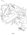
- Fig. 1 illustrates a perspective view of the optical measuring device 10 according to the invention, in which a test strip 12 extends in the measuring plane 14 (cf. Fig. 2 ) in its measuring position.
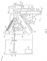
- Fig. 2 shows a cross-section through the measuring device of Fig. 1 along A-A'.
- An illumination means 16 is illustrated by means of which a strip-shaped portion of the measuring plane, in which the test strip 12 is in its measuring position, may be illuminated with different colors.
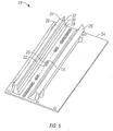
- Fig. 5 shows a perspective view of the illumination means 16.
- the illumination means 16 comprise blue 18, green 20 and orange 22 LEDs having wavelengths of 450 nm, 530 nm and 620 nm in a serial order on a transmitter board 24. This serial arrangement of the LEDs is particularly suitable for illuminating the strip-shaped portion on the measuring plane 14.
- blue 18, green 20 and orange LEDs 22 are respectively placed closely adjacent to one another in one group so that the measuring plane is uniformly illuminated in all three colors with the same intensity distribution.
- the groups of LEDs are arranged in a series such that their arrangement density of light sources on the transmitter board increases within the series from the center in an outward direction. This inhomogeneous arrangement of LEDs in a series results in an almost homogeneous illumination intensity on the measuring plane in the field of the test strip.
- screens 26 are disposed which focus the light emitted by the LEDs onto a strip-shaped portion, in which the test strip extends in its measuring position.
- the screens 26 extend over the entire length of the LED series. They comprise four surface segments 28, 30, 32 and 34, extending over the entire length of the screen 26. The inclination angle of the surface segments increases relative to the transmission board 24 in correspondence with an increasing distance therefrom.
- the screens 26 are made of parts having been manufactured by injection molding and whose surfaces 28, 30, 32 and 34 are provided with a reflecting layer.
- the light emitted by the illumination unit 16 is diffusely reflected at the test strip 12 and the test strip is imaged via an optical system onto a planar image sensor 36, which is disposed in a housing 38 that is impermeable against light.
- the optical system comprises a mirror 40, a lens 42 and a screen 44.
- it is not the test strip 12 but the second reference surface 58 that is imaged onto the image sensor 36. Since the second reference surface 58, as will be described in more detail below, takes the position of a test strip during measuring, the position of the image 46 of the test strip is the same as the one of the image of the reference surface.
- the generation of the image 46 at the image sensor 36 is illustrated by means of two exemplary rays of light 48, 50.
- the optical path is folded at the mirror 40 thus maintaining the measuring device in its entirety compact.
- the image sensor 36 comprises a plurality of light sensitive CMOS parts generating a signal depending on the intensity of the light illuminating them.
- the light sensitive elements are arranged in a planar matrix and each of them serves to generate an image point (pixel) of the image 46.
- one of a plurality of light sensitive sensor elements is selected.
- Light is imaged onto the sensor element by the optical system, the light being diffusely reflected from a certain point, i.e. a very small portion, in one of the test fields.
- the sensor element detects the intensity of the light reflected at that point. If now this point is illuminated three times sequentially with blue, green and orange light having the same intensity, the relations of intensities measured at the sensor element represent the relative reflectivity for light of these three colors. Thus, however, the color of the test field is clearly determined.
- the signals generated at the image sensor 36 are transmitted to an evaluation unit 52 that detects the color of the original image, i.e. of the point or small portion on the test field, from these three signals generated upon a three-time illumination at each of the image points. Due to the plurality of light sensitive sensor elements which are comprised in the image sensor 36, the determination of color may be performed sequentially for a corresponding number of pixels in the test plane.
- the evaluation unit 52 gains information about the relation of intensities of the different colors at one pixel in the measuring plane so that it may be taken into account when calculating the relative reflectivity.
- the measuring device may be calibrated according to the illumination conditions.
- the illumination of the measuring plane may vary in the course of time for a great number of reasons, e.g. due to the wear of the LEDs, defective LEDs or even only due to contaminations in the illumination means. As a consequence, the measuring device has to be calibrated anew.
- the measuring device 10 For immediately determining during operation a change of intensity of illumination of the measuring plane, the measuring device 10 according to the invention is provided with a first reference surface 54, which is arranged such that it is illuminated by the illumination unit 16 together with the test strip and imaged by the optical system onto the image sensor 36.
- This first reference surface 54 is illustrated in Fig. 2 and its image on the image sensor 36 has been designated 56.
- the evaluation unit 52 causes the self-calibration of the measuring device.
- a second reference surface 58 is provided which is adjustable from a second position, in which it is not illuminated by the illumination means 16 and not imaged by the optical system onto the image sensor 36, to a first position, in which it takes the position of a test strip during measurement.
- the image of this second reference surface 58 serves to calibrate the measuring means.
- the measuring device may be used for a test strip analysis apparatus, in which the test strips are advanced towards the measuring device placed across transport belts 60. It is particularly advantageous to provide a construction in which the transport belts 60 form a conveying surface which coincides with the measuring plane. Thus, the test strip 12 may be measured lying on the transport belt 60. However, this requires holding and aligning the test strip in its measuring position.
- two pins 62 are provided that are movable along their longitudinal axis between a first position in which they protrude into said measuring plane (cf. Fig. 1 and Fig. 4 ) and a second position in which they are entirely outside said measuring plane (cf. Fig. 2 and Fig. 3 ).
- the pins 62 are biased into their second position by a spring and adjustable to their first position by a lever element 66 against the biasing force.
- the second reference surface 58 is defined by a surface of a strip-shaped plate 68 whose first end is equipped with a first arm 70 perpendicular relative to the reference surface 58, this arm being pivotable with respect to an axis 72 (cf. Fig. 2 ) parallel to reference surface 58.
- a second arm is mounted to the second end of the strip-shaped plate, this arm being parallel with respect to the first arm and also pivotable about the axis 72.
- This arm is not shown in the drawings since it extends in a region of the measuring device, that is cut away in Figures 2 to 4 .
- the strip-shaped plate 68 and the first and second arms form a U-shaped part.
- a bar 74 is pivotally mounted with its first end via a joint 76 to a free end of the first arm 70.
- This bar is also pivotally mounted with its second end via a joint 76 to a first lever 78.
- This first lever 78 is pivotable about an axis 80 between a first and a second position.
- This axis 80 is realized by a bolt, which, however, is not shown in Fig. 3 and 4 .
- the first lever 78 is in its first lever position. The lever is biased into this position by means of a spring 82.
- the first lever 78 is adjustable from its first into its second position by means of an eccentric drive against the biasing force of the spring 82.
- the eccentric drive is formed by a rotating disc 84 that is driven by a motor, not shown, and on which a pin 68 is mounted perpendicularly thereto.
- the pin 86 engages the first lever 78 and moves it into the second lever position, as shown in Fig. 2 and 3 , against the biasing force of the spring 82.
- the second reference surface 68 is moved into its second position by means of the bar 74 and the first arm 70.
- the lever element 66 is pivotable about an axis 88.
- This axis 88 is realized by a bolt which is not shown in Fig. 3 and 4 .
- the spring 82 is fixed to this bolt.
- the end 90 of the lever element 66 is free so that the springs 64 of the pins 62 relax and take their second position in which they lie completely outside the measuring plane.
- the disc 84 upon rotation of the disc 84 from this position in its second rotational direction (cf. Fig.
- the first lever 78 is moved by the spring 82 into its first position, whereby the reference surface 68 moves into its second position.
- the pin 86 engages the end 90 of the lever element 66 after rotation about a certain angle and pivots the lever element about the axis 88 such that the pins 62 are moved into their second position against the biasing force of the spring 64. This is the position taken during measurement of a test strip, namely in which the second reference surface 68 is turned out of the optical path and the pins 62 protrude into the measuring plane, so that a test strip 12 may be aligned and held by them.
- the adjustment mechanism described facilitates adjustment between a calibration position, in which the second reference surface 68 takes its first position and in which the pins 62 take their second position, and a measuring position, in which the second reference surface 68 takes its second position and the pins 62 take their first position.
Landscapes
- Physics & Mathematics (AREA)
- Spectroscopy & Molecular Physics (AREA)
- General Physics & Mathematics (AREA)
- Health & Medical Sciences (AREA)
- Life Sciences & Earth Sciences (AREA)
- Biochemistry (AREA)
- Analytical Chemistry (AREA)
- General Health & Medical Sciences (AREA)
- Chemical & Material Sciences (AREA)
- Immunology (AREA)
- Pathology (AREA)
- Molecular Biology (AREA)
- Investigating Or Analysing Materials By Optical Means (AREA)
- Spectrometry And Color Measurement (AREA)
Description
- The present invention concerns an optical measuring device for detecting the coloring of test fields of a test strip, which is wetted with a liquid for detecting substances in said liquid, whereupon the reflectivity of the test fields changes depending on the concentration of the substances to be detected, comprising
- a measuring plane wherein said test strip is to be placed,
- an illumination device for illuminating the measuring plane,
- a planar image sensor,
- an optical system for imaging said measuring plane onto the image sensor, and
- an electronic evaluation unit for evaluation of the signals detected by said image sensor.
- Optical measuring devices of this kind are e.g. known as part of test strip analysis apparatus, which are used for examining urine or blood test strips in doctor's practices, hospitals or medical laboratories. The test strips to be analyzed often comprise a plurality of test fields, each of which serves to detect another substance. In such measuring devices, the test strip is illuminated as a whole and imaged onto the image sensor. From the image obtained, the electronic evaluation unit may then determine the coloring of all test fields across the test strip. Thus, it is not necessary to scan the individual test fields and the measurement of the test strip may be conducted in a shorter time, wherein the structure of the measuring device is simpler.
- For detecting the coloring of a test field, its reflectivity for light of three different wavelengths has to be determined. In a conventional measuring device, the test strip is illuminated with white light and imaged onto an image sensor comprising sensor elements, each of which is sensitive to one of three wavelengths (colors). The light-sensitive elements are arranged in a planar matrix whose lines each comprise sensor elements sensitive to the light of the same color. Thus, there are three types of such color lines comprised in the image sensor, the order of adjacent color lines being such that one color line of the first type is followed by one of the second type and one of the second type is followed by one of the third type and one of the third type is followed by one of the first type.
- Thus, three images are effectively detected by the image sensor sequentially, each time one of the entirety of color lines of one type, which represent the intensity of three spectral components of the same colored picture. From the intensity of the spectral components in every image point, basically a colored image may be calculated.
- However, a problem is posed by the fact that these three images do not really represent the spectral components of the same image points since the color lines are offset from each other. If now these three images are taken for color evaluation, a systematic error occurs due to the finite width of the color lines.
- Therefore, the present invention is to solve the problem of providing an optical measuring device of the above-mentioned kind, which avoids this systematic error. This problem is solved by an optical measuring device of the above kind in that the illumination device comprises light sources of different colors or other means that serve to alternatively illuminate the measuring plane with different colors and in that the electronic evaluation means detects the coloring of the test fields from the images obtained under different illumination.
- Thus, the measuring device of the present invention does not require an image sensor having color lines but an image sensor whose light-sensitive elements detect the intensity of the light received independent from its wavelength. In the images obtained under different color illumination, the same image point (i.e. the signal received under different color illumination at the same sensor element) is generated by a light that has been reflected on the same point on the test strip. From the relative reflectivity of these points under different color illumination, the respective color may be calculated without any systematic errors occurring.
- In a preferred embodiment, the image sensor comprises light-sensitive CMOS components arranged in a planar matrix.
- The illumination unit uses colored LEDs as light sources. The light sources comprise blue, green and orange LEDs, preferably LEDs having wavelengths of 450 nm, 530 nm and 620 nm.
- In order to uniformly illuminate a test strip in a measuring plane, it is advantageous to arrange the light sources in a series on a transmitter board. It is especially advantageous if the arrangement density of light sources on the transmitter board increases within the series from the center in an outward direction. Due to such inhomogeneous distribution of light sources on the transmitter board, the test strip may be almost homogeneously illuminated in the measuring plane.
- In a further preferred embodiment, on both sides of the series of light sources in parallel to the longitudinal direction of the series, screens are employed which focus the light emitted by the light sources on a strip-shaped portion in the measuring plane in which the test strip is to be placed. The screens preferably extend substantially over the length of the series of light sources and comprise a plurality of surface segments extending over the entire length of the transmitter board, wherein said surface segments' inclination angle relative to the transmitter board increases in correspondence with an increasing distance therefrom. With these screens, a test strip in the measuring plane may be illuminated with high intensity but nevertheless almost homogeneously.
- The screens preferably consist of parts that have been milled or manufactured by injection molding, said parts having a reflecting layer or being laminated with a reflecting film. Thus, the screens are stable and can be manufactured at low cost.
- As has been mentioned above, the color of a test field is detected by the relative reflectivity of the test field for light of three different wavelengths. If, for example, a test field is illuminated three times in a row with lights of different colors that, however, have different intensities, the relative reflectivity corresponds to the relation of intensities that are detected by the image sensor in the image of the test field. However, it is not indispensably necessary to permanently illuminate the test strip with light of the same intensity. What is important is that the intensity of illumination is known, thus, the relative reflectivity can be calculated from the measured intensities at the image sensor. Further, it may occur that the intensity of illumination changes in operation. If, e.g. colored LEDs are used for the illumination means, these are subject to wear which diminishes their performance.
- For detecting a change of illumination intensity during operation it is advantageous to provide a first reference surface that is arranged such that it is illuminated by the illumination unit together with the test strip and imaged by the optical system onto the image sensor. By means of the image of this reference surface, the electronic evaluation unit may determine any illumination changes, such as a change in intensity of illumination with one of the colors as a whole or only within a portion of the measuring plane. In case such change is determined, it is necessary to newly calibrate the measuring device.
- For calibration of the measuring device, the local intensity distribution on the measuring plane for all three colors has to be known. Preferably, the optical measuring device therefore has a second reference surface adjustable between a first position in which it takes the position of a test strip during measuring and a second position in which it cannot be imaged by the optical system onto the image sensor. The optical measuring device may thus calibrate itself by an adjustment of the second surface to the first position, an illumination subsequently with the different colors and by using the images provided by the evaluation unit as calibration standard. Such calibration procedure may for example routinely be carried out by the measuring device upon switching on the measuring device or after a predetermined amount of measurements has been made.
- In an advantageous embodiment, the second reference surface is formed by a surface of a strip-shaped plate whose first end is equipped with a first arm at least almost perpendicular with respect to said second reference surface and pivotable about an axis parallel with respect to the reference surface. By adjusting the arm, the second reference surface can be adjusted between its first and second positions. Preferably, a second arm is further mounted to the second end of the strip-shaped plate, said arm being substantially parallel with the first arm and pivotable about the same axis as the first arm. The first arm is discharged by the second arm.
- Preferably, a bar is pivotally supported with its first end by the first arm for adjusting the second reference surface between its first and its second position. In a preferred embodiment, this bar is mounted with its second end to a first lever pivotable about a first lever axis and biased into a first lever position by means of a biasing element, in which position the reference surface takes its second position and the lever is adjustable against the biasing force of the biasing element to a second lever position in which the reference surface takes its first position. Preferably, the first lever is actuated by means of an eccentric drive.
- The device according to the invention may be used as part of a test strip analysis apparatus in which the test strips usually are advanced towards the measuring means by means of belts or the like. However, when measured, the test strip has to be in a static condition. This is most simply obtained when the conveying surface of the transport means of the test strip analysis apparatus lies in the measuring plane and the test strip is shortly kept in its measuring position on the conveying surface. In an advantageous embodiment, the optical measuring device therefore comprises a means for holding and aligning a test strip in its measuring position.
- Preferably, these means are defined by two at least almost parallel pins movable along their longitudinal axis between a first position in which they protrude into said measuring plane and a second position in which they are entirely outside said measuring plane. In their first position, these pins protrude into the measuring plane so that a test strip conveyed in the measuring plane is caught at the pins and aligns relative to these pins in a measuring position. Preferably, the pins are biased into their second position and adjustable against the biasing force to their first position by a lever element. Preferably, the lever element is adjusted by the same eccentric drive as the first lever.
- In a particularly preferred embodiment, the eccentric drive is formed by a rotating disc driven by a motor, on the surface of which a pin is arranged perpendicularly thereto such that upon rotation of the disc in its first rotational direction, said pin engagingly moves said first lever into its second lever position and that upon rotation of the disc in its second rotational direction, said pin engagingly moves said lever element such that said lever element moves said pins into their first position.
- Even though, the optical measuring device according to the invention makes use of an illumination means that is able to alternatively illuminate the measuring plane with different colors, all of the features concerning the arrangement of the light sources, the screens, the first and second reference surfaces, the adjustment mechanism of the second reference surface and the means for holding and aligning a test strip in its measuring position may also be advantageously used with conventional measuring means, in which white light for illuminating and filters, i.e. image sensors having color lines are used.
- Further advantages and features of the solution according to the invention will become apparent from the following description which outlines the invention by means of an embodiment with reference to the accompanying drawings, wherein
- Fig. 1
- is a perspective view of the optical measuring means according to the invention;
- Fig. 2
- is a cross-section through a portion of the optical measuring device along A-A' in
Fig. 1 , - Fig. 3
- is a perspective view of the section of
Fig. 2 with the second reference surface in its first position, - Fig. 4
- corresponds with
Fig. 3 , wherein the second reference surface is in its second position and a test strip in its measuring position, and - Fig. 5
- is a perspective view of the illumination unit.
-
Fig. 1 illustrates a perspective view of theoptical measuring device 10 according to the invention, in which atest strip 12 extends in the measuring plane 14 (cf.Fig. 2 ) in its measuring position. -
Fig. 2 shows a cross-section through the measuring device ofFig. 1 along A-A'. An illumination means 16 is illustrated by means of which a strip-shaped portion of the measuring plane, in which thetest strip 12 is in its measuring position, may be illuminated with different colors.Fig. 5 shows a perspective view of the illumination means 16. The illumination means 16 comprise blue 18, green 20 andorange 22 LEDs having wavelengths of 450 nm, 530 nm and 620 nm in a serial order on atransmitter board 24. This serial arrangement of the LEDs is particularly suitable for illuminating the strip-shaped portion on the measuringplane 14. Within the series, blue 18, green 20 andorange LEDs 22 are respectively placed closely adjacent to one another in one group so that the measuring plane is uniformly illuminated in all three colors with the same intensity distribution. The groups of LEDs are arranged in a series such that their arrangement density of light sources on the transmitter board increases within the series from the center in an outward direction. This inhomogeneous arrangement of LEDs in a series results in an almost homogeneous illumination intensity on the measuring plane in the field of the test strip. - In parallel to the longitudinal direction of the LED series, screens 26 are disposed which focus the light emitted by the LEDs onto a strip-shaped portion, in which the test strip extends in its measuring position. The
screens 26 extend over the entire length of the LED series. They comprise foursurface segments screen 26. The inclination angle of the surface segments increases relative to thetransmission board 24 in correspondence with an increasing distance therefrom. Thescreens 26 are made of parts having been manufactured by injection molding and whosesurfaces - The light emitted by the
illumination unit 16 is diffusely reflected at thetest strip 12 and the test strip is imaged via an optical system onto aplanar image sensor 36, which is disposed in ahousing 38 that is impermeable against light. The optical system comprises amirror 40, alens 42 and ascreen 44. InFig. 2 it is not thetest strip 12 but thesecond reference surface 58 that is imaged onto theimage sensor 36. Since thesecond reference surface 58, as will be described in more detail below, takes the position of a test strip during measuring, the position of theimage 46 of the test strip is the same as the one of the image of the reference surface. InFig. 2 , the generation of theimage 46 at theimage sensor 36 is illustrated by means of two exemplary rays oflight mirror 40 thus maintaining the measuring device in its entirety compact. - The
image sensor 36 comprises a plurality of light sensitive CMOS parts generating a signal depending on the intensity of the light illuminating them. The light sensitive elements are arranged in a planar matrix and each of them serves to generate an image point (pixel) of theimage 46. - In the following, it shall be described how to detect the coloring of the test fields of the
test strip 12 by means of the measuring device according to the invention. For this purpose, one of a plurality of light sensitive sensor elements is selected. Light is imaged onto the sensor element by the optical system, the light being diffusely reflected from a certain point, i.e. a very small portion, in one of the test fields. Thus, the sensor element detects the intensity of the light reflected at that point. If now this point is illuminated three times sequentially with blue, green and orange light having the same intensity, the relations of intensities measured at the sensor element represent the relative reflectivity for light of these three colors. Thus, however, the color of the test field is clearly determined. The signals generated at theimage sensor 36 are transmitted to anevaluation unit 52 that detects the color of the original image, i.e. of the point or small portion on the test field, from these three signals generated upon a three-time illumination at each of the image points. Due to the plurality of light sensitive sensor elements which are comprised in theimage sensor 36, the determination of color may be performed sequentially for a corresponding number of pixels in the test plane. - For determining the relative reflectivity it is certainly not necessary to illuminate each pixel in each color with light having the same intensity. What is important is that the
evaluation unit 52 gains information about the relation of intensities of the different colors at one pixel in the measuring plane so that it may be taken into account when calculating the relative reflectivity. By resorting to this information, the measuring device may be calibrated according to the illumination conditions. However, the illumination of the measuring plane may vary in the course of time for a great number of reasons, e.g. due to the wear of the LEDs, defective LEDs or even only due to contaminations in the illumination means. As a consequence, the measuring device has to be calibrated anew. - For immediately determining during operation a change of intensity of illumination of the measuring plane, the measuring
device 10 according to the invention is provided with afirst reference surface 54, which is arranged such that it is illuminated by theillumination unit 16 together with the test strip and imaged by the optical system onto theimage sensor 36. Thisfirst reference surface 54 is illustrated inFig. 2 and its image on theimage sensor 36 has been designated 56. As soon as there is a change of illumination, theimage 56 changes on theimage sensor 36, which in turn is detected by theevaluation unit 52. Then, theevaluation unit 52 causes the self-calibration of the measuring device. - However, for calibrating the measuring means, the
image 56 of thefirst reference surface 54 cannot be resorted to since the illumination intensity distribution on thefirst reference surface 54 is not identical with the one in the measuring plane. Therefore, asecond reference surface 58 is provided which is adjustable from a second position, in which it is not illuminated by the illumination means 16 and not imaged by the optical system onto theimage sensor 36, to a first position, in which it takes the position of a test strip during measurement. The image of thissecond reference surface 58 serves to calibrate the measuring means. - As shown in
Fig. 1 andFig. 4 , the measuring device according to the invention may be used for a test strip analysis apparatus, in which the test strips are advanced towards the measuring device placed acrosstransport belts 60. It is particularly advantageous to provide a construction in which thetransport belts 60 form a conveying surface which coincides with the measuring plane. Thus, thetest strip 12 may be measured lying on thetransport belt 60. However, this requires holding and aligning the test strip in its measuring position. - With regard to the illustrated measuring device two
pins 62 are provided that are movable along their longitudinal axis between a first position in which they protrude into said measuring plane (cf.Fig. 1 andFig. 4 ) and a second position in which they are entirely outside said measuring plane (cf.Fig. 2 andFig. 3 ). Thepins 62 are biased into their second position by a spring and adjustable to their first position by alever element 66 against the biasing force. - In the following, the adjustment mechanism of the
pins 62 and thesecond reference surface 58 is described. Thesecond reference surface 58 is defined by a surface of a strip-shapedplate 68 whose first end is equipped with afirst arm 70 perpendicular relative to thereference surface 58, this arm being pivotable with respect to an axis 72 (cf.Fig. 2 ) parallel toreference surface 58. A second arm is mounted to the second end of the strip-shaped plate, this arm being parallel with respect to the first arm and also pivotable about theaxis 72. This arm is not shown in the drawings since it extends in a region of the measuring device, that is cut away inFigures 2 to 4 . The strip-shapedplate 68 and the first and second arms form a U-shaped part. - For adjustment of the second reference surface between its first and its second position, a
bar 74 is pivotally mounted with its first end via a joint 76 to a free end of thefirst arm 70. This bar is also pivotally mounted with its second end via a joint 76 to afirst lever 78. Thisfirst lever 78 is pivotable about anaxis 80 between a first and a second position. Thisaxis 80 is realized by a bolt, which, however, is not shown inFig. 3 and4 . InFig. 4 , thefirst lever 78 is in its first lever position. The lever is biased into this position by means of aspring 82. Upon thelever 78 taking this first lever position, thesecond reference surface 68 is adjusted via thebar 74 and thefirst arm 70 into its second position. - The
first lever 78 is adjustable from its first into its second position by means of an eccentric drive against the biasing force of thespring 82. The eccentric drive is formed by arotating disc 84 that is driven by a motor, not shown, and on which apin 68 is mounted perpendicularly thereto. Upon rotation of the disc in its first rotational direction (cf.Fig. 1 to 4 , in a clockwise direction) thepin 86 engages thefirst lever 78 and moves it into the second lever position, as shown inFig. 2 and3 , against the biasing force of thespring 82. Thus, thesecond reference surface 68 is moved into its second position by means of thebar 74 and thefirst arm 70. - The
lever element 66 is pivotable about anaxis 88. Thisaxis 88 is realized by a bolt which is not shown inFig. 3 and4 . Thespring 82 is fixed to this bolt. In a position of thedisc 84, in which thepin 86 holds thesecond lever 78 in its second lever position against the biasing force of thespring 82, as is the case inFig. 2 and3 , theend 90 of thelever element 66 is free so that thesprings 64 of thepins 62 relax and take their second position in which they lie completely outside the measuring plane. However, upon rotation of thedisc 84 from this position in its second rotational direction (cf.Fig. 1 to 4 , in a clockwise direction), thefirst lever 78 is moved by thespring 82 into its first position, whereby thereference surface 68 moves into its second position. On the other hand, thepin 86 engages theend 90 of thelever element 66 after rotation about a certain angle and pivots the lever element about theaxis 88 such that thepins 62 are moved into their second position against the biasing force of thespring 64. This is the position taken during measurement of a test strip, namely in which thesecond reference surface 68 is turned out of the optical path and thepins 62 protrude into the measuring plane, so that atest strip 12 may be aligned and held by them. - Therefore, by using a single eccentric drive, the adjustment mechanism described facilitates adjustment between a calibration position, in which the
second reference surface 68 takes its first position and in which thepins 62 take their second position, and a measuring position, in which thesecond reference surface 68 takes its second position and thepins 62 take their first position.
Claims (6)
- An optical measuring device (10) for detecting the coloring of test fields of a test strip (12) to be wetted with a liquid for detecting substances in said liquid, whereupon the reflectivity of the test fields changes depending on the concentrations of the substances to be detected, comprising:a measuring plane (14) upon which said test strip (12) is to be placed;an illumination device (16) for illuminating the measuring plane (14) and the test strip (12);a planar image sensor (36);an optical system (40, 42, 44) for providing an image of the test strip (12) onto said planar image sensor (36); andan electronic evaluation unit (52) for evaluating at least one signal generated by said planar image sensor (36),wherein said illumination device (16) comprises light sources of different colors, wherein said light sources of said illumination device (16) comprise light emitting diodes (LEDs),characterised by
said LEDs comprising blue (18), green (20) and orange (22) LEDs, to alternatively illuminate said test strip (12) with said different colors such that said electronic evaluation unit (52) detects the coloring of said test fields under different color illuminations,wherein said LEDs are arranged in a series on a transmitter board (24),wherein within the series, blue (18), green (20) and orange (22) LEDs are respectively placed closely adjacent to one another in one group so that the measuring plane is uniformly illuminated in all three colors with the same intensity distribution,wherein the groups of LEDs are arranged in the series such that their arrangement density of LEDs on the transmitter board (24) increases within the series from the center in an outward direction, wherein this inhomogeneous arrangement of LEDs in a series results in an almost homogeneous illumination intensity on the measuring plane in the field of the test strip. - An optical measuring device according to claim 1, wherein said image sensor (36) comprises light sensitive CMOS elements arranged in a planar matrix.
- An optical measuring device according to claim 1, wherein said LEDs have approximate wavelengths of 450 nm, 530 nm and 620 nm, respectively.
- An optical measuring device according to claim 1, further comprising a screen on each side of the series of LEDs, wherein said screens are disposed in parallel to the longitudinal direction of a test strip so as to focus light reflected from the LEDs onto the test strip.
- An optical measuring device according to claim 4, wherein said screens (26) substantially extend over the length of the series of LEDs and comprise a plurality of surface segments (28, 30, 32, 34) extending over the entire length, wherein said surface segments' inclination angle relative to said transmitter board (24) increases in correspondence with an increasing distance from the transmitter board (24).
- An optical measuring device according to claims 4 or 5, wherein said screens comprise parts having been milled or manufactured by injection molding, said parts having a reflecting layer or being laminated with a reflecting film.
Applications Claiming Priority (3)
| Application Number | Priority Date | Filing Date | Title |
|---|---|---|---|
| DE10156804 | 2001-11-20 | ||
| DE10156804A DE10156804B4 (en) | 2001-11-20 | 2001-11-20 | Optical measuring device for test strips |
| PCT/US2002/036885 WO2003044474A1 (en) | 2001-11-20 | 2002-11-18 | Optical measuring device for test strips |
Publications (3)
| Publication Number | Publication Date |
|---|---|
| EP1459040A1 EP1459040A1 (en) | 2004-09-22 |
| EP1459040A4 EP1459040A4 (en) | 2012-01-18 |
| EP1459040B1 true EP1459040B1 (en) | 2017-05-03 |
Family
ID=7706268
Family Applications (1)
| Application Number | Title | Priority Date | Filing Date |
|---|---|---|---|
| EP02798444.2A Expired - Lifetime EP1459040B1 (en) | 2001-11-20 | 2002-11-18 | Optical measuring device for test strips |
Country Status (7)
| Country | Link |
|---|---|
| EP (1) | EP1459040B1 (en) |
| JP (2) | JP2005509880A (en) |
| CN (1) | CN100483087C (en) |
| AU (1) | AU2002363929A1 (en) |
| DE (1) | DE10156804B4 (en) |
| TW (1) | TWI266048B (en) |
| WO (1) | WO2003044474A1 (en) |
Cited By (2)
| Publication number | Priority date | Publication date | Assignee | Title |
|---|---|---|---|---|
| EP3408648A4 (en) * | 2016-01-28 | 2019-03-06 | Siemens Healthcare Diagnostics Inc. | METHODS AND APPARATUS FOR IMAGING A SAMPLE AND / OR SAMPLE CONTAINER USING MULTIPLE EXHIBITIONS |
| US12352748B2 (en) | 2018-09-21 | 2025-07-08 | Foss Analytical A/S | Lateral flow assay device and analyser |
Families Citing this family (10)
| Publication number | Priority date | Publication date | Assignee | Title |
|---|---|---|---|---|
| DE10156804B4 (en) * | 2001-11-20 | 2011-03-17 | Quidel Corp., San Diego | Optical measuring device for test strips |
| US7688438B2 (en) * | 2005-12-20 | 2010-03-30 | Raytheon Company | Scanning solar diffuser relative reflectance monitor |
| DE102006018544A1 (en) * | 2006-04-21 | 2007-10-25 | Mayr-Melnhof Karton Ag | Packaging and use of fragrances in a package |
| CN101118217B (en) * | 2007-09-10 | 2010-05-19 | 西安近代化学研究所 | Vieri experiment indicator paper colors identification device |
| CN101620371B (en) * | 2008-07-02 | 2011-03-30 | 比亚迪股份有限公司 | Camera Test Device |
| CN101738385B (en) * | 2008-11-24 | 2011-09-21 | 周礼君 | Tubular waveguide plasmon resonance sensing device and sensing system |
| KR101202648B1 (en) * | 2011-07-22 | 2012-11-19 | (주)대경산업 | Digital reader for urin detection |
| SE536431C2 (en) | 2011-11-23 | 2013-10-29 | Calmark Sweden Ab | Test system arrangement and method of testing |
| SE536430C2 (en) * | 2011-11-23 | 2013-10-29 | Calmark Sweden Ab | Test system arrangement and method of testing |
| EP4720635A1 (en) * | 2023-05-24 | 2026-04-08 | Inito Health Inc. | Slab-based optical device, system, and method to capture image of test device |
Citations (1)
| Publication number | Priority date | Publication date | Assignee | Title |
|---|---|---|---|---|
| US6115184A (en) * | 1998-11-13 | 2000-09-05 | Xerox Corporation | Light collector for an LED array |
Family Cites Families (20)
| Publication number | Priority date | Publication date | Assignee | Title |
|---|---|---|---|---|
| DE3407754A1 (en) * | 1984-03-02 | 1985-09-12 | Boehringer Mannheim Gmbh, 6800 Mannheim | DEVICE FOR DETERMINING THE DIFFUSION REFLECTIVITY OF A SAMPLE AREA OF SMALL DIMENSIONS |
| US4935346A (en) * | 1986-08-13 | 1990-06-19 | Lifescan, Inc. | Minimum procedure system for the determination of analytes |
| JPH01204481A (en) * | 1988-02-10 | 1989-08-17 | Iwasaki Electric Co Ltd | Led linear light source |
| DE3914037A1 (en) * | 1989-04-28 | 1990-10-31 | Boehringer Mannheim Gmbh | TEST CARRIER ANALYZER |
| JP2771309B2 (en) * | 1990-04-17 | 1998-07-02 | アルプス電気株式会社 | Optical reader |
| JPH04345417A (en) * | 1991-05-21 | 1992-12-01 | Sanyo Electric Co Ltd | Pallet carrying type conveyer |
| JP3559975B2 (en) * | 1992-09-10 | 2004-09-02 | テラメックス株式会社 | Analysis method using test pieces |
| JP3250328B2 (en) * | 1993-07-22 | 2002-01-28 | スズキ株式会社 | Work transfer device |
| DE4420260C2 (en) * | 1994-06-10 | 1998-08-06 | Alfred Prof Dr Ing Leipertz | Method for determining color value components and color saturation |
| IT1273968B (en) * | 1995-02-24 | 1997-07-11 | Finmeccanica Spa | EQUIPMENT FOR THE OPTICAL DETECTION OF SURFACE DEFECTS IN PARTICULAR FOR LAMINATED TAPES |
| US5695949A (en) * | 1995-04-07 | 1997-12-09 | Lxn Corp. | Combined assay for current glucose level and intermediate or long-term glycemic control |
| JP3660761B2 (en) * | 1996-10-03 | 2005-06-15 | 技術研究組合医療福祉機器研究所 | Method and apparatus for measuring absorption information of scatterers |
| US5877863A (en) * | 1997-03-20 | 1999-03-02 | Bayer Corporation | Readhead for a photometric diagnostic instrument |
| JPH112635A (en) * | 1997-06-12 | 1999-01-06 | Kdk Corp | Carrying device of strip piece and analytical instrument equipped with this device |
| CA2308063A1 (en) * | 1997-10-31 | 1999-05-14 | Technical Chemicals & Products, Inc. | Reflectometer |
| US6124585A (en) * | 1998-10-27 | 2000-09-26 | Umm Electronics, Inc. | Apparatus for measuring the reflectance of strips having non-uniform color |
| JP3650558B2 (en) * | 1999-11-09 | 2005-05-18 | 株式会社日立製作所 | Reflectance measuring device |
| JP2001183309A (en) * | 1999-12-27 | 2001-07-06 | Asahi Glass Co Ltd | Apparatus and method for evaluating homogeneity of transparent plate |
| JP4031824B2 (en) * | 2001-05-22 | 2008-01-09 | ゼロックス コーポレイション | Color correction system for color printing and spectrophotometer |
| DE10156804B4 (en) * | 2001-11-20 | 2011-03-17 | Quidel Corp., San Diego | Optical measuring device for test strips |
-
2001
- 2001-11-20 DE DE10156804A patent/DE10156804B4/en not_active Expired - Lifetime
-
2002
- 2002-11-18 AU AU2002363929A patent/AU2002363929A1/en not_active Abandoned
- 2002-11-18 WO PCT/US2002/036885 patent/WO2003044474A1/en not_active Ceased
- 2002-11-18 CN CNB02826424XA patent/CN100483087C/en not_active Expired - Lifetime
- 2002-11-18 EP EP02798444.2A patent/EP1459040B1/en not_active Expired - Lifetime
- 2002-11-18 JP JP2003546060A patent/JP2005509880A/en not_active Withdrawn
- 2002-11-20 TW TW091133823A patent/TWI266048B/en not_active IP Right Cessation
-
2009
- 2009-02-09 JP JP2009027916A patent/JP2009236901A/en active Pending
Patent Citations (1)
| Publication number | Priority date | Publication date | Assignee | Title |
|---|---|---|---|---|
| US6115184A (en) * | 1998-11-13 | 2000-09-05 | Xerox Corporation | Light collector for an LED array |
Cited By (3)
| Publication number | Priority date | Publication date | Assignee | Title |
|---|---|---|---|---|
| EP3408648A4 (en) * | 2016-01-28 | 2019-03-06 | Siemens Healthcare Diagnostics Inc. | METHODS AND APPARATUS FOR IMAGING A SAMPLE AND / OR SAMPLE CONTAINER USING MULTIPLE EXHIBITIONS |
| US10928310B2 (en) | 2016-01-28 | 2021-02-23 | Siemens Healthcare Diagnostics Inc. | Methods and apparatus for imaging a specimen container and/or specimen using multiple exposures |
| US12352748B2 (en) | 2018-09-21 | 2025-07-08 | Foss Analytical A/S | Lateral flow assay device and analyser |
Also Published As
| Publication number | Publication date |
|---|---|
| JP2005509880A (en) | 2005-04-14 |
| TW200303420A (en) | 2003-09-01 |
| TWI266048B (en) | 2006-11-11 |
| DE10156804A1 (en) | 2003-07-03 |
| AU2002363929A1 (en) | 2003-06-10 |
| CN100483087C (en) | 2009-04-29 |
| WO2003044474A1 (en) | 2003-05-30 |
| CN1610822A (en) | 2005-04-27 |
| EP1459040A4 (en) | 2012-01-18 |
| EP1459040A1 (en) | 2004-09-22 |
| DE10156804B4 (en) | 2011-03-17 |
| JP2009236901A (en) | 2009-10-15 |
Similar Documents
| Publication | Publication Date | Title |
|---|---|---|
| JP2009236901A (en) | Optical measuring device for test strip | |
| JP3559975B2 (en) | Analysis method using test pieces | |
| JP3895772B2 (en) | Apparatus and method for inspecting sheet material such as banknotes or securities | |
| US5452080A (en) | Image inspection apparatus and method | |
| JP2004138519A (en) | Film thickness measuring device, reflectivity measuring device, foreign matter inspection device, reflectivity measuring method and foreign matter inspection method | |
| US11758278B2 (en) | Optical apparatus | |
| JP7692467B2 (en) | Circuit board with built-in light source | |
| US20170336256A1 (en) | Method and apparatus for color measurement of non-solid colors | |
| EP2691759B1 (en) | High flux collimated illuminator and method of uniform field illumination | |
| WO2009067358A1 (en) | Miniature optical readhead and colorimeter for analysis media | |
| US7623240B2 (en) | Optical measuring device for test strips | |
| US4898467A (en) | Spectrometer apparatus for self-calibrating color imaging apparatus | |
| JP2005509880A5 (en) | ||
| US9019499B2 (en) | Tunable light source system and method having wavelength reference capability | |
| JP2003501753A (en) | Array structure for detecting finger and / or palm surface structures | |
| JP2008507694A (en) | Read head for optical diagnostic equipment | |
| US11893429B2 (en) | Colorimetric device, image forming apparatus, and calibration method | |
| US20240255441A1 (en) | Apparatus for detecting surface defects in objects | |
| EP1914529B1 (en) | Method for analyzing the apparent colour and the gonio reflectance of an object | |
| US12301770B2 (en) | Information processing apparatus, abnormality detection method, storage medium, and information processing system | |
| EP3256825A1 (en) | Method and apparatus for color measurement of non-solid colors | |
| JP3578559B2 (en) | Absorbance measuring device and dispensing device provided with the same | |
| JP2001513594A (en) | Method and apparatus for position detection and / or coplanarity inspection and / or separation inspection of device terminals | |
| WO2017135956A1 (en) | Method and apparatus for color measurement of non-solid colors | |
| JP4569316B2 (en) | Spectral colorimeter |
Legal Events
| Date | Code | Title | Description |
|---|---|---|---|
| PUAI | Public reference made under article 153(3) epc to a published international application that has entered the european phase |
Free format text: ORIGINAL CODE: 0009012 |
|
| 17P | Request for examination filed |
Effective date: 20040616 |
|
| AK | Designated contracting states |
Kind code of ref document: A1 Designated state(s): AT BE BG CH CY CZ DE DK EE ES FI FR GB GR IE IT LI LU MC NL PT SE SK TR |
|
| AX | Request for extension of the european patent |
Extension state: AL LT LV MK RO SI |
|
| REG | Reference to a national code |
Ref country code: DE Ref legal event code: R079 Ref document number: 60248860 Country of ref document: DE Free format text: PREVIOUS MAIN CLASS: G01J0003000000 Ipc: G01J0003500000 |
|
| A4 | Supplementary search report drawn up and despatched |
Effective date: 20111219 |
|
| RIC1 | Information provided on ipc code assigned before grant |
Ipc: G01N 21/86 20060101ALI20111213BHEP Ipc: G01N 21/25 20060101ALI20111213BHEP Ipc: G01J 3/50 20060101AFI20111213BHEP |
|
| 17Q | First examination report despatched |
Effective date: 20120531 |
|
| RAP1 | Party data changed (applicant data changed or rights of an application transferred) |
Owner name: BECKMAN COULTER GMBH |
|
| GRAP | Despatch of communication of intention to grant a patent |
Free format text: ORIGINAL CODE: EPIDOSNIGR1 |
|
| INTG | Intention to grant announced |
Effective date: 20161115 |
|
| GRAS | Grant fee paid |
Free format text: ORIGINAL CODE: EPIDOSNIGR3 |
|
| GRAA | (expected) grant |
Free format text: ORIGINAL CODE: 0009210 |
|
| AK | Designated contracting states |
Kind code of ref document: B1 Designated state(s): AT BE BG CH CY CZ DE DK EE ES FI FR GB GR IE IT LI LU MC NL PT SE SK TR |
|
| REG | Reference to a national code |
Ref country code: GB Ref legal event code: FG4D |
|
| REG | Reference to a national code |
Ref country code: AT Ref legal event code: REF Ref document number: 890497 Country of ref document: AT Kind code of ref document: T Effective date: 20170515 Ref country code: CH Ref legal event code: EP |
|
| REG | Reference to a national code |
Ref country code: IE Ref legal event code: FG4D |
|
| REG | Reference to a national code |
Ref country code: DE Ref legal event code: R096 Ref document number: 60248860 Country of ref document: DE |
|
| REG | Reference to a national code |
Ref country code: NL Ref legal event code: MP Effective date: 20170503 |
|
| REG | Reference to a national code |
Ref country code: AT Ref legal event code: MK05 Ref document number: 890497 Country of ref document: AT Kind code of ref document: T Effective date: 20170503 |
|
| PG25 | Lapsed in a contracting state [announced via postgrant information from national office to epo] |
Ref country code: FI Free format text: LAPSE BECAUSE OF FAILURE TO SUBMIT A TRANSLATION OF THE DESCRIPTION OR TO PAY THE FEE WITHIN THE PRESCRIBED TIME-LIMIT Effective date: 20170503 Ref country code: ES Free format text: LAPSE BECAUSE OF FAILURE TO SUBMIT A TRANSLATION OF THE DESCRIPTION OR TO PAY THE FEE WITHIN THE PRESCRIBED TIME-LIMIT Effective date: 20170503 Ref country code: AT Free format text: LAPSE BECAUSE OF FAILURE TO SUBMIT A TRANSLATION OF THE DESCRIPTION OR TO PAY THE FEE WITHIN THE PRESCRIBED TIME-LIMIT Effective date: 20170503 Ref country code: GR Free format text: LAPSE BECAUSE OF FAILURE TO SUBMIT A TRANSLATION OF THE DESCRIPTION OR TO PAY THE FEE WITHIN THE PRESCRIBED TIME-LIMIT Effective date: 20170804 |
|
| REG | Reference to a national code |
Ref country code: FR Ref legal event code: PLFP Year of fee payment: 16 |
|
| PG25 | Lapsed in a contracting state [announced via postgrant information from national office to epo] |
Ref country code: SE Free format text: LAPSE BECAUSE OF FAILURE TO SUBMIT A TRANSLATION OF THE DESCRIPTION OR TO PAY THE FEE WITHIN THE PRESCRIBED TIME-LIMIT Effective date: 20170503 Ref country code: NL Free format text: LAPSE BECAUSE OF FAILURE TO SUBMIT A TRANSLATION OF THE DESCRIPTION OR TO PAY THE FEE WITHIN THE PRESCRIBED TIME-LIMIT Effective date: 20170503 Ref country code: BG Free format text: LAPSE BECAUSE OF FAILURE TO SUBMIT A TRANSLATION OF THE DESCRIPTION OR TO PAY THE FEE WITHIN THE PRESCRIBED TIME-LIMIT Effective date: 20170803 |
|
| PG25 | Lapsed in a contracting state [announced via postgrant information from national office to epo] |
Ref country code: CZ Free format text: LAPSE BECAUSE OF FAILURE TO SUBMIT A TRANSLATION OF THE DESCRIPTION OR TO PAY THE FEE WITHIN THE PRESCRIBED TIME-LIMIT Effective date: 20170503 Ref country code: DK Free format text: LAPSE BECAUSE OF FAILURE TO SUBMIT A TRANSLATION OF THE DESCRIPTION OR TO PAY THE FEE WITHIN THE PRESCRIBED TIME-LIMIT Effective date: 20170503 Ref country code: SK Free format text: LAPSE BECAUSE OF FAILURE TO SUBMIT A TRANSLATION OF THE DESCRIPTION OR TO PAY THE FEE WITHIN THE PRESCRIBED TIME-LIMIT Effective date: 20170503 Ref country code: EE Free format text: LAPSE BECAUSE OF FAILURE TO SUBMIT A TRANSLATION OF THE DESCRIPTION OR TO PAY THE FEE WITHIN THE PRESCRIBED TIME-LIMIT Effective date: 20170503 |
|
| REG | Reference to a national code |
Ref country code: DE Ref legal event code: R097 Ref document number: 60248860 Country of ref document: DE |
|
| PLBE | No opposition filed within time limit |
Free format text: ORIGINAL CODE: 0009261 |
|
| STAA | Information on the status of an ep patent application or granted ep patent |
Free format text: STATUS: NO OPPOSITION FILED WITHIN TIME LIMIT |
|
| 26N | No opposition filed |
Effective date: 20180206 |
|
| PG25 | Lapsed in a contracting state [announced via postgrant information from national office to epo] |
Ref country code: MC Free format text: LAPSE BECAUSE OF FAILURE TO SUBMIT A TRANSLATION OF THE DESCRIPTION OR TO PAY THE FEE WITHIN THE PRESCRIBED TIME-LIMIT Effective date: 20170503 |
|
| GBPC | Gb: european patent ceased through non-payment of renewal fee |
Effective date: 20171118 |
|
| PG25 | Lapsed in a contracting state [announced via postgrant information from national office to epo] |
Ref country code: LI Free format text: LAPSE BECAUSE OF NON-PAYMENT OF DUE FEES Effective date: 20171130 Ref country code: CH Free format text: LAPSE BECAUSE OF NON-PAYMENT OF DUE FEES Effective date: 20171130 |
|
| PG25 | Lapsed in a contracting state [announced via postgrant information from national office to epo] |
Ref country code: LU Free format text: LAPSE BECAUSE OF NON-PAYMENT OF DUE FEES Effective date: 20171118 |
|
| REG | Reference to a national code |
Ref country code: BE Ref legal event code: MM Effective date: 20171130 |
|
| REG | Reference to a national code |
Ref country code: IE Ref legal event code: MM4A |
|
| PG25 | Lapsed in a contracting state [announced via postgrant information from national office to epo] |
Ref country code: IE Free format text: LAPSE BECAUSE OF NON-PAYMENT OF DUE FEES Effective date: 20171118 |
|
| PG25 | Lapsed in a contracting state [announced via postgrant information from national office to epo] |
Ref country code: GB Free format text: LAPSE BECAUSE OF NON-PAYMENT OF DUE FEES Effective date: 20171118 Ref country code: BE Free format text: LAPSE BECAUSE OF NON-PAYMENT OF DUE FEES Effective date: 20171130 |
|
| PG25 | Lapsed in a contracting state [announced via postgrant information from national office to epo] |
Ref country code: CY Free format text: LAPSE BECAUSE OF NON-PAYMENT OF DUE FEES Effective date: 20170503 |
|
| REG | Reference to a national code |
Ref country code: DE Ref legal event code: R082 Ref document number: 60248860 Country of ref document: DE Representative=s name: ZWICKER SCHNAPPAUF & PARTNER PATENTANWAELTE PA, DE |
|
| PG25 | Lapsed in a contracting state [announced via postgrant information from national office to epo] |
Ref country code: TR Free format text: LAPSE BECAUSE OF FAILURE TO SUBMIT A TRANSLATION OF THE DESCRIPTION OR TO PAY THE FEE WITHIN THE PRESCRIBED TIME-LIMIT Effective date: 20170503 |
|
| PG25 | Lapsed in a contracting state [announced via postgrant information from national office to epo] |
Ref country code: PT Free format text: LAPSE BECAUSE OF FAILURE TO SUBMIT A TRANSLATION OF THE DESCRIPTION OR TO PAY THE FEE WITHIN THE PRESCRIBED TIME-LIMIT Effective date: 20170503 |
|
| PGFP | Annual fee paid to national office [announced via postgrant information from national office to epo] |
Ref country code: FR Payment date: 20210930 Year of fee payment: 20 |
|
| PGFP | Annual fee paid to national office [announced via postgrant information from national office to epo] |
Ref country code: DE Payment date: 20210923 Year of fee payment: 20 |
|
| PGFP | Annual fee paid to national office [announced via postgrant information from national office to epo] |
Ref country code: IT Payment date: 20211012 Year of fee payment: 20 |
|
| REG | Reference to a national code |
Ref country code: DE Ref legal event code: R071 Ref document number: 60248860 Country of ref document: DE |
|
| P01 | Opt-out of the competence of the unified patent court (upc) registered |
Effective date: 20230529 |