EP1457754B1 - Multitubularer Turm für hoch-energetische Munition - Google Patents
Multitubularer Turm für hoch-energetische Munition Download PDFInfo
- Publication number
- EP1457754B1 EP1457754B1 EP04290579A EP04290579A EP1457754B1 EP 1457754 B1 EP1457754 B1 EP 1457754B1 EP 04290579 A EP04290579 A EP 04290579A EP 04290579 A EP04290579 A EP 04290579A EP 1457754 B1 EP1457754 B1 EP 1457754B1
- Authority
- EP
- European Patent Office
- Prior art keywords
- axis
- carriage
- turret according
- tubes
- site
- Prior art date
- Legal status (The legal status is an assumption and is not a legal conclusion. Google has not performed a legal analysis and makes no representation as to the accuracy of the status listed.)
- Expired - Lifetime
Links
- 238000010304 firing Methods 0.000 claims description 18
- 230000005484 gravity Effects 0.000 description 7
- 230000000694 effects Effects 0.000 description 3
- 238000013459 approach Methods 0.000 description 2
- 239000003638 chemical reducing agent Substances 0.000 description 2
- 230000008094 contradictory effect Effects 0.000 description 1
- 238000006073 displacement reaction Methods 0.000 description 1
- 238000010079 rubber tapping Methods 0.000 description 1
Images

Classifications
-
- F—MECHANICAL ENGINEERING; LIGHTING; HEATING; WEAPONS; BLASTING
- F41—WEAPONS
- F41A—FUNCTIONAL FEATURES OR DETAILS COMMON TO BOTH SMALLARMS AND ORDNANCE, e.g. CANNONS; MOUNTINGS FOR SMALLARMS OR ORDNANCE
- F41A27/00—Gun mountings permitting traversing or elevating movement, e.g. gun carriages
- F41A27/06—Mechanical systems
- F41A27/08—Bearings, e.g. trunnions; Brakes or blocking arrangements
Definitions
- the technical sector of the present invention is that of turrets and turrets weapon system. Such a cupola is described in the document US 4,437,384 .
- turrets with two degrees of freedom They carry a weapon system comprising at least one tube.
- the tube of this weapon system can be oriented in two degrees of freedom, to coincide / point the axis of the tube in the direction of fire.
- the weapon system can be rotated relative to a lyre, around a first axis site, usually horizontal.
- the block constituted by the weapon system and the lyre can in turn be rotated around a second bearing axis, usually vertical.
- Each of the two rotation axes in site and in the field is generally motorized and can be controlled.
- Gun-type devices are known having several tubes mounted in battery. They are not steerable and have an important rigid structure capable of supporting the efforts.
- the propulsion of the ammunition uses a rocket effect. In this case she is self-propelled. It transmits little effort to the cupola.
- Two or two-tube missile turret systems are known. Each tube is usually single-use and can not be recharged. The multiplicity of shots is possible in sequence and / or simultaneously. The number of shots is limited to the number of tubes initially present.
- the invention relates to a cupola for high energy munition, comprising a weapon system, rotatable about a first axis site, relative to a lyre, itself rotatable about a second axis bearing , relative to a chassis, characterized in that the weapon system comprises a plurality of tubes, fixed on a carriage for successively bringing each of the tubes into a firing position such that the axis of the tube is concurrent with the site axes and deposit.
- the movement of the carriage is such that it reproduces an arrangement of the tubes on the carriage identical to itself each time a tube is fed into the firing position.
- the carriage is driven by a translation movement and the tubes are parallel to each other and aligned in the direction of said translation.
- the direction of said translation is parallel to the site axis.
- the direction of said translation is perpendicular to the site axis.
- the mobile carriage is positionable in an equilibrium position during the transport and pointing phases.
- the carriage is rotated about a third axis and the tubes are parallel to each other and arranged in a circle centered on this third axis.
- this third axis is perpendicular to the site axis.
- the carriage is driven in a rotational movement about a third axis and the tubes are arranged radially in a circle centered on this third axis.
- the third axis is parallel to the site axis.
- the third axis is perpendicular to the site axis.
- An advantage of the device according to the invention is to enable the impact of the couples induced by the recoil force to be limited.
- Another advantage of the device according to the invention is, by reducing the torques, to allow adoption of lightweight turret structural parts.
- Another advantage of the device according to the invention is, by reducing the torques, to substantially reduce the size and capacity of the drive and motorization means of the site and deposit axes.
- Another advantage of the device according to the invention is, by reducing the structural elements and the drive and drive components, to reduce the cost of the device.
- Another advantage of the device according to the invention is, by reducing the structural elements and the drive and drive components, to reduce the mass balance of the device.
- the device object of the present invention comprises a weapon system 1.
- This weapon system 1 comprises several tubes 6 fixed on a carriage 7.
- the weapon system is rotatable about a site axis 2.
- the site axis 2 is horizontal. This rotation is made with respect to a lyre 3.
- This lyre 3 can, in turn, turn about the bearing axis 4 relative to the frame 5.
- the bearing axis 4 is vertical.
- the frame is fixed on a fixed carriage or on a vehicle, whose cupola contributes to ensure safety.
- the torque is reduced or vanished, provided that the axis 8 of the tube 6 approaches or is in concurrency with the axis deposit 4.
- the preferred firing position 9 for a tube 6 is such that its axis 8 is concurrent with the two axes site 2 and bearing 4.
- the mobile carriage 7 has the function of carrying and moving the tubes 6 to bring them successively into the firing position 9.
- a configuration consists of arranging n tubes 6 on a carousel, in a plane arrangement and radially around the axis of rotation of said carousel. This axis may be, parallel to the axis of rotation of site 2.
- Each tube 6 is successively brought to the firing position 9 by a rotation of one nth of a revolution of the carousel.
- the arrangement of the tubes 6 is circular and in relation to the circular rotation of the carriage 7 is reproduced identical to itself, each rotation of one nth of a turn.
- the figure 1 shows an exemplary configuration with two tubes 6 and a carriage 7 moving in translation in a direction perpendicular to the axis site 2.
- the representation places the bottom tube, in the plane of the figure, in the firing position 9.
- the trolley is shown in the upper position, in the plane of the figure.
- the arrangement of the tubes 6 is such that they are arranged along a first straight line.
- the movement of the carriage 7 is a translation along a second straight line.
- the relation between the arrangement of the tubes and the movement of the carriage is here, the parallelism of these two lines.
- the figure 2 presents a variant of the previous configuration.
- This example shows two tubes 6 and a carriage 7 moving in translation in a direction parallel to the axis site 2.
- the representation shows the tube 6 of the left, in the plane of the figure, in firing position 9, the carriage being positioned to the left, in the plane of the figure.
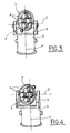
- the figure 3 represents an example configuration with four tubes 6 and a rotary carriage 7.
- the tubes are here, for illustrative purposes, parallel to each other and to the axis of rotation of the carriage 7.
- the tube at the bottom, in the plane of the figure, is in the firing position 9.
- the tubes 6 are arranged according to a circle. The rotational movement of the carriage 7 reproduces this circle.
- the figure 4 represents a variant of the previous configuration.
- This example has four tubes 6 and a rotating carriage 7.
- the rightmost tube, in the plane of the figure, is in firing position 9.
- An offset has been made in the lyre 3.
- the weapon system 1 in addition to the recoil force, is subjected to gravitational forces.
- the transport phases where the cupola is moved for example by its carrier or pointing vehicle during which the weapon system is moved by the movements of the axes site 2 and deposit 4
- the weapon system under the effect of the own weight of the system d 1 and / or the assembly grouping the lyre 3 and the weapon system 1
- the lever arms determining these couples depend on the distance between the center of gravity of a moving part and the axis of rotation.
- a first lever arm appears between the center of gravity of the weapon system 1 and the axis of rotation site 2.
- a second lever arm appears between the center of gravity of the movable portion in the bearing, gathering the lyre 3 and the weapon system 1, and the axis of rotation deposit 4.
- the carriage 7 for positioning the tubes 6 can be used in order to move the tubes to a position of equilibrium that brings the center of gravity closer to the axis of rotation.
- an equilibrium position located between the two firing positions 9 of the two tubes 6, brings the center of gravity of the moving part into alignment, as close as possible to the axis of rotation bearing 4.
Landscapes
- Engineering & Computer Science (AREA)
- General Engineering & Computer Science (AREA)
- Aiming, Guidance, Guns With A Light Source, Armor, Camouflage, And Targets (AREA)
- Manipulator (AREA)
- Magnetic Resonance Imaging Apparatus (AREA)
- Physical Or Chemical Processes And Apparatus (AREA)
Claims (11)
- Drehkranz für Munition mit hoher Energie, umfassend ein Waffensystem (1), das um eine erste Achse zur Elevation (2) in Bezug auf eine Gabel (3) beweglich ist, wobei sie selbst um eine zweite Achse (4) zur horizontalen Ausrichtung in Bezug auf ein Gehäuse (5) beweglich ist, dadurch gekennzeichnet, dass das Waffensystem (1) mehrere Rohre (6) umfasst, die an einem Wagen (7) befestigt sind, der es ermöglicht, jedes der Rohre (6) nacheinander derart in eine Abschussposition (9) zu bringen, dass die Achse (8) des Rohres (6) zu den Achsen zur Elevation (2) und zur horizontalen Ausrichtung (3) konvergent ist.
- Drehkranz nach Anspruch 1, dadurch gekennzeichnet, dass die Bewegung des Wagens (7) derartig ist, dass sie eine Anordnung der Rohre (6) auf dem Wagen (7) reproduziert, die bei jeder Zuführung eines Rohres (6) in die Abschussposition (9) mit sich selbst identisch ist.
- Drehkranz nach Anspruch 2, dadurch gekennzeichnet, dass dem Wagen (7) eine Translationsbewegung verliehen wird und dass die Rohre (6) parallel zueinander und gemäß der Richtung der genannten Translation ausgerichtet sind.
- Drehkranz nach Anspruch 3, dadurch gekennzeichnet, dass die Richtung der genannten Translation parallel zur Achse zur Elevation (2) ist.
- Drehkranz nach Anspruch 3, dadurch gekennzeichnet, dass die Richtung der genannten Translation senkrecht zur Achse zur Elevation (2) ist.
- Drehkranz nach irgendeinem der Ansprüche 3 bis 5, dadurch gekennzeichnet, dass der Wagen (7) während der Transport- und Richtphasen in einer Gleichgewichtsposition positionierbar ist.
- Drehkranz nach Anspruch 2, dadurch gekennzeichnet, dass dem Wagen (7) eine Drehbewegung um eine dritte Achse verliehen wird und dass die Rohre (6) parallel zueinander und gemäß einem um diese dritte Achse zentrierten Kreis angeordnet sind.
- Drehkranz nach Anspruch 7, dadurch gekennzeichnet, dass die dritte Achse senkrecht zur Achse zur Elevation (2) ist.
- Drehkranz nach Anspruch 2, dadurch gekennzeichnet, dass dem Wagen (7) eine Drehbewegung um eine dritte Achse verliehen wird und dass die Rohre (6) radial gemäß einem um diese dritte Achse zentrierten Kreis angeordnet sind.
- Drehkranz nach Anspruch 9, dadurch gekennzeichnet, dass die dritte Achse parallel zur Achse zur Elevation (2) ist.
- Drehkranz nach Anspruch 9, dadurch gekennzeichnet, dass die dritte Achse senkrecht zur Achse zur Elevation (2) ist.
Applications Claiming Priority (2)
| Application Number | Priority Date | Filing Date | Title |
|---|---|---|---|
| FR0303127 | 2003-03-13 | ||
| FR0303127A FR2852385B1 (fr) | 2003-03-13 | 2003-03-13 | Tourelleau multitube pour munition a haute energie |
Publications (3)
| Publication Number | Publication Date |
|---|---|
| EP1457754A1 EP1457754A1 (de) | 2004-09-15 |
| EP1457754B1 true EP1457754B1 (de) | 2009-11-11 |
| EP1457754B2 EP1457754B2 (de) | 2013-03-20 |
Family
ID=32749790
Family Applications (1)
| Application Number | Title | Priority Date | Filing Date |
|---|---|---|---|
| EP04290579A Expired - Lifetime EP1457754B2 (de) | 2003-03-13 | 2004-03-03 | Multitubularer Turm für hoch-energetische Munition |
Country Status (4)
| Country | Link |
|---|---|
| EP (1) | EP1457754B2 (de) |
| AT (1) | ATE448460T1 (de) |
| DE (1) | DE602004023984D1 (de) |
| FR (1) | FR2852385B1 (de) |
Cited By (1)
| Publication number | Priority date | Publication date | Assignee | Title |
|---|---|---|---|---|
| DE102010016542C5 (de) * | 2010-04-20 | 2017-08-17 | Krauss-Maffei Wegmann Gmbh & Co. Kg | Vorrichtung und Verfahren zum Richten eines Abschussbehälters |
Families Citing this family (1)
| Publication number | Priority date | Publication date | Assignee | Title |
|---|---|---|---|---|
| DE102008038603C5 (de) | 2008-08-21 | 2018-04-19 | Krauss-Maffei Wegmann Gmbh & Co. Kg | Gegenschussanlage |
Family Cites Families (10)
| Publication number | Priority date | Publication date | Assignee | Title |
|---|---|---|---|---|
| DE307117C (de) † | ||||
| US3126791A (en) * | 1964-03-31 | Gun recoil torque eliminator | ||
| DE303267C (de) † | 1900-01-01 | |||
| DE2028992C1 (de) * | 1970-06-12 | 1978-04-27 | Thyssen Industrie Ag, 4300 Essen | Anordnung einer Rohrwaffe in einem stabilisierten Geschützturm |
| GB2004037B (en) † | 1977-09-10 | 1982-03-24 | Rheinmetall Gmbh | Mortar |
| DE2750776C3 (de) † | 1977-11-14 | 1980-06-04 | Precitronic Gesellschaft Fuer Feinmechanik Und Electronic Mbh, 2000 Hamburg | Azimutal richtbare Abschußvorrichtung |
| US4437384A (en) * | 1981-08-17 | 1984-03-20 | General Electric Company | Gun mount |
| CH675473A5 (en) † | 1988-07-15 | 1990-09-28 | Oerlikon Buehrle Ag | Firearm with housing, barrel, and shell chamber - has each chamber in separate link detachable from chamber groups |
| US5282455A (en) † | 1992-06-11 | 1994-02-01 | The Walt Disney Company | Launcher for launching multiple fireworks projectiles |
| DE10008198A1 (de) † | 2000-02-23 | 2001-08-30 | Krauss Maffei Wegmann Gmbh & C | An einem Kampffahrzeug angeordnete Wurfanlage für Nebelkerzen, Sprengkörper u. dgl. |
-
2003
- 2003-03-13 FR FR0303127A patent/FR2852385B1/fr not_active Expired - Fee Related
-
2004
- 2004-03-03 DE DE602004023984T patent/DE602004023984D1/de not_active Expired - Lifetime
- 2004-03-03 AT AT04290579T patent/ATE448460T1/de not_active IP Right Cessation
- 2004-03-03 EP EP04290579A patent/EP1457754B2/de not_active Expired - Lifetime
Cited By (1)
| Publication number | Priority date | Publication date | Assignee | Title |
|---|---|---|---|---|
| DE102010016542C5 (de) * | 2010-04-20 | 2017-08-17 | Krauss-Maffei Wegmann Gmbh & Co. Kg | Vorrichtung und Verfahren zum Richten eines Abschussbehälters |
Also Published As
| Publication number | Publication date |
|---|---|
| EP1457754A1 (de) | 2004-09-15 |
| ATE448460T1 (de) | 2009-11-15 |
| FR2852385A1 (fr) | 2004-09-17 |
| EP1457754B2 (de) | 2013-03-20 |
| DE602004023984D1 (de) | 2009-12-24 |
| FR2852385B1 (fr) | 2005-06-03 |
Similar Documents
| Publication | Publication Date | Title |
|---|---|---|
| FR2649667A1 (fr) | Procede de lancement dans l'espace d'une capsule et moyen de lancement correspondant | |
| EP1617163B1 (de) | Abschiessvorrichtung für Geschosse | |
| WO2009017615A1 (en) | High velocity mass accelerator and method of use thereof | |
| US5267503A (en) | Ammunition transfer device | |
| EP1457754B1 (de) | Multitubularer Turm für hoch-energetische Munition | |
| JPH0418235B2 (de) | ||
| EP0018920B1 (de) | Waffensystem mit grosser Orientierungsbeweglichkeit | |
| EP0023441A1 (de) | Militärisches Material mit einem Panzerturm, auf welchem aussen eine Kanone angebracht ist | |
| EP0435771B1 (de) | Turm für Leichtpanzer, ausgerüstet mit einer seitlich angebrachten Waffe | |
| WO1985001792A1 (fr) | Dispositif de chargement automatique pour canon | |
| FR2850174A1 (fr) | Systemes asservis d'actionnement | |
| EP1395789B1 (de) | Waffenrichtvorrichtung | |
| US6752063B2 (en) | Multiple cell ammunition cradle | |
| EP4148370B1 (de) | Automatische nachladevorrichtung für eine waffe mit doppelmagazinzuführung und waffensystem damit | |
| EP1248066B1 (de) | Verfahren und Vorrichtung zur Munitionsladung für eine in einem Schiff angeordnete Rohrwaffe | |
| WO2004023058A1 (fr) | Systeme de defense d'une cible comprenant un dispositif lanceur de projectiles | |
| EP3179194B1 (de) | Haltevorrichtung einer granate für artilleriewaffe | |
| EP0727635B1 (de) | Hilfsvorrichtung zur Ladung einer Artilleriekanone | |
| FR2467379A1 (fr) | Tourelle de char a chargement automatique de l'arme | |
| EP1248067B1 (de) | Automatische Munitionsladevorrichtung für eine in einem Panzerturm angeordnete Rohrwaffe | |
| EP4201801B1 (de) | Lager zum lagern und handhaben von waffen, z.b. in einem schiff, und schiff mit einem solchen lager | |
| EP3867591B1 (de) | Magazin für eine grosskalibrige waffe und mit einem solchen magazin versehener revolver | |
| FR2688302A1 (fr) | Lanceur de projectiles furtif. | |
| FR2562229A1 (fr) | Dispositif de transport de munitions pour un canon pointable en hauteur | |
| EP0559548A1 (de) | Mobiler Munitionswerfer der den Stress des Schützen vermeidet |
Legal Events
| Date | Code | Title | Description |
|---|---|---|---|
| PUAI | Public reference made under article 153(3) epc to a published international application that has entered the european phase |
Free format text: ORIGINAL CODE: 0009012 |
|
| AK | Designated contracting states |
Kind code of ref document: A1 Designated state(s): AT BE BG CH CY CZ DE DK EE ES FI FR GB GR HU IE IT LI LU MC NL PL PT RO SE SI SK TR |
|
| AX | Request for extension of the european patent |
Extension state: AL LT LV MK |
|
| 17P | Request for examination filed |
Effective date: 20050118 |
|
| AKX | Designation fees paid |
Designated state(s): AT BE BG CH CY CZ DE DK EE ES FI FR GB GR HU IE IT LI LU MC NL PL PT RO SE SI SK TR |
|
| RAP1 | Party data changed (applicant data changed or rights of an application transferred) |
Owner name: NEXTER SYSTEMS |
|
| GRAP | Despatch of communication of intention to grant a patent |
Free format text: ORIGINAL CODE: EPIDOSNIGR1 |
|
| GRAS | Grant fee paid |
Free format text: ORIGINAL CODE: EPIDOSNIGR3 |
|
| GRAA | (expected) grant |
Free format text: ORIGINAL CODE: 0009210 |
|
| AK | Designated contracting states |
Kind code of ref document: B1 Designated state(s): AT BE BG CH CY CZ DE DK EE ES FI FR GB GR HU IE IT LI LU MC NL PL PT RO SE SI SK TR |
|
| REG | Reference to a national code |
Ref country code: GB Ref legal event code: FG4D Free format text: NOT ENGLISH |
|
| REG | Reference to a national code |
Ref country code: CH Ref legal event code: EP |
|
| REG | Reference to a national code |
Ref country code: IE Ref legal event code: FG4D |
|
| REF | Corresponds to: |
Ref document number: 602004023984 Country of ref document: DE Date of ref document: 20091224 Kind code of ref document: P |
|
| REG | Reference to a national code |
Ref country code: SE Ref legal event code: TRGR |
|
| NLV1 | Nl: lapsed or annulled due to failure to fulfill the requirements of art. 29p and 29m of the patents act | ||
| PG25 | Lapsed in a contracting state [announced via postgrant information from national office to epo] |
Ref country code: ES Free format text: LAPSE BECAUSE OF FAILURE TO SUBMIT A TRANSLATION OF THE DESCRIPTION OR TO PAY THE FEE WITHIN THE PRESCRIBED TIME-LIMIT Effective date: 20100222 Ref country code: PT Free format text: LAPSE BECAUSE OF FAILURE TO SUBMIT A TRANSLATION OF THE DESCRIPTION OR TO PAY THE FEE WITHIN THE PRESCRIBED TIME-LIMIT Effective date: 20100311 Ref country code: FI Free format text: LAPSE BECAUSE OF FAILURE TO SUBMIT A TRANSLATION OF THE DESCRIPTION OR TO PAY THE FEE WITHIN THE PRESCRIBED TIME-LIMIT Effective date: 20091111 |
|
| PG25 | Lapsed in a contracting state [announced via postgrant information from national office to epo] |
Ref country code: SI Free format text: LAPSE BECAUSE OF FAILURE TO SUBMIT A TRANSLATION OF THE DESCRIPTION OR TO PAY THE FEE WITHIN THE PRESCRIBED TIME-LIMIT Effective date: 20091111 Ref country code: PL Free format text: LAPSE BECAUSE OF FAILURE TO SUBMIT A TRANSLATION OF THE DESCRIPTION OR TO PAY THE FEE WITHIN THE PRESCRIBED TIME-LIMIT Effective date: 20091111 Ref country code: CY Free format text: LAPSE BECAUSE OF FAILURE TO SUBMIT A TRANSLATION OF THE DESCRIPTION OR TO PAY THE FEE WITHIN THE PRESCRIBED TIME-LIMIT Effective date: 20091111 |
|
| REG | Reference to a national code |
Ref country code: IE Ref legal event code: FD4D |
|
| PG25 | Lapsed in a contracting state [announced via postgrant information from national office to epo] |
Ref country code: AT Free format text: LAPSE BECAUSE OF FAILURE TO SUBMIT A TRANSLATION OF THE DESCRIPTION OR TO PAY THE FEE WITHIN THE PRESCRIBED TIME-LIMIT Effective date: 20091111 |
|
| PG25 | Lapsed in a contracting state [announced via postgrant information from national office to epo] |
Ref country code: EE Free format text: LAPSE BECAUSE OF FAILURE TO SUBMIT A TRANSLATION OF THE DESCRIPTION OR TO PAY THE FEE WITHIN THE PRESCRIBED TIME-LIMIT Effective date: 20091111 Ref country code: RO Free format text: LAPSE BECAUSE OF FAILURE TO SUBMIT A TRANSLATION OF THE DESCRIPTION OR TO PAY THE FEE WITHIN THE PRESCRIBED TIME-LIMIT Effective date: 20091111 Ref country code: DK Free format text: LAPSE BECAUSE OF FAILURE TO SUBMIT A TRANSLATION OF THE DESCRIPTION OR TO PAY THE FEE WITHIN THE PRESCRIBED TIME-LIMIT Effective date: 20091111 Ref country code: IE Free format text: LAPSE BECAUSE OF FAILURE TO SUBMIT A TRANSLATION OF THE DESCRIPTION OR TO PAY THE FEE WITHIN THE PRESCRIBED TIME-LIMIT Effective date: 20091111 Ref country code: BG Free format text: LAPSE BECAUSE OF FAILURE TO SUBMIT A TRANSLATION OF THE DESCRIPTION OR TO PAY THE FEE WITHIN THE PRESCRIBED TIME-LIMIT Effective date: 20100211 |
|
| PLBI | Opposition filed |
Free format text: ORIGINAL CODE: 0009260 |
|
| PG25 | Lapsed in a contracting state [announced via postgrant information from national office to epo] |
Ref country code: CZ Free format text: LAPSE BECAUSE OF FAILURE TO SUBMIT A TRANSLATION OF THE DESCRIPTION OR TO PAY THE FEE WITHIN THE PRESCRIBED TIME-LIMIT Effective date: 20091111 Ref country code: SK Free format text: LAPSE BECAUSE OF FAILURE TO SUBMIT A TRANSLATION OF THE DESCRIPTION OR TO PAY THE FEE WITHIN THE PRESCRIBED TIME-LIMIT Effective date: 20091111 |
|
| PLAX | Notice of opposition and request to file observation + time limit sent |
Free format text: ORIGINAL CODE: EPIDOSNOBS2 |
|
| 26 | Opposition filed |
Opponent name: RHEINMETALL WAFFE MUNITION GMBH Effective date: 20100810 |
|
| BERE | Be: lapsed |
Owner name: NEXTER SYSTEMS Effective date: 20100331 |
|
| PG25 | Lapsed in a contracting state [announced via postgrant information from national office to epo] |
Ref country code: GR Free format text: LAPSE BECAUSE OF FAILURE TO SUBMIT A TRANSLATION OF THE DESCRIPTION OR TO PAY THE FEE WITHIN THE PRESCRIBED TIME-LIMIT Effective date: 20100212 Ref country code: MC Free format text: LAPSE BECAUSE OF NON-PAYMENT OF DUE FEES Effective date: 20100331 |
|
| REG | Reference to a national code |
Ref country code: CH Ref legal event code: PL |
|
| GBPC | Gb: european patent ceased through non-payment of renewal fee |
Effective date: 20100303 |
|
| PLBB | Reply of patent proprietor to notice(s) of opposition received |
Free format text: ORIGINAL CODE: EPIDOSNOBS3 |
|
| PG25 | Lapsed in a contracting state [announced via postgrant information from national office to epo] |
Ref country code: CH Free format text: LAPSE BECAUSE OF NON-PAYMENT OF DUE FEES Effective date: 20100331 Ref country code: BE Free format text: LAPSE BECAUSE OF NON-PAYMENT OF DUE FEES Effective date: 20100331 Ref country code: LI Free format text: LAPSE BECAUSE OF NON-PAYMENT OF DUE FEES Effective date: 20100331 |
|
| PG25 | Lapsed in a contracting state [announced via postgrant information from national office to epo] |
Ref country code: IT Free format text: LAPSE BECAUSE OF FAILURE TO SUBMIT A TRANSLATION OF THE DESCRIPTION OR TO PAY THE FEE WITHIN THE PRESCRIBED TIME-LIMIT Effective date: 20091111 Ref country code: GB Free format text: LAPSE BECAUSE OF NON-PAYMENT OF DUE FEES Effective date: 20100303 |
|
| PG25 | Lapsed in a contracting state [announced via postgrant information from national office to epo] |
Ref country code: NL Free format text: LAPSE BECAUSE OF FAILURE TO SUBMIT A TRANSLATION OF THE DESCRIPTION OR TO PAY THE FEE WITHIN THE PRESCRIBED TIME-LIMIT Effective date: 20091111 Ref country code: LU Free format text: LAPSE BECAUSE OF NON-PAYMENT OF DUE FEES Effective date: 20100303 Ref country code: HU Free format text: LAPSE BECAUSE OF FAILURE TO SUBMIT A TRANSLATION OF THE DESCRIPTION OR TO PAY THE FEE WITHIN THE PRESCRIBED TIME-LIMIT Effective date: 20100512 |
|
| PG25 | Lapsed in a contracting state [announced via postgrant information from national office to epo] |
Ref country code: TR Free format text: LAPSE BECAUSE OF FAILURE TO SUBMIT A TRANSLATION OF THE DESCRIPTION OR TO PAY THE FEE WITHIN THE PRESCRIBED TIME-LIMIT Effective date: 20091111 |
|
| PUAH | Patent maintained in amended form |
Free format text: ORIGINAL CODE: 0009272 |
|
| STAA | Information on the status of an ep patent application or granted ep patent |
Free format text: STATUS: PATENT MAINTAINED AS AMENDED |
|
| 27A | Patent maintained in amended form |
Effective date: 20130320 |
|
| AK | Designated contracting states |
Kind code of ref document: B2 Designated state(s): AT BE BG CH CY CZ DE DK EE ES FI FR GB GR HU IE IT LI LU MC NL PL PT RO SE SI SK TR |
|
| REG | Reference to a national code |
Ref country code: DE Ref legal event code: R102 Ref document number: 602004023984 Country of ref document: DE Effective date: 20130320 |
|
| REG | Reference to a national code |
Ref country code: SE Ref legal event code: RPEO |
|
| PGFP | Annual fee paid to national office [announced via postgrant information from national office to epo] |
Ref country code: DE Payment date: 20150219 Year of fee payment: 12 |
|
| PGFP | Annual fee paid to national office [announced via postgrant information from national office to epo] |
Ref country code: SE Payment date: 20150224 Year of fee payment: 12 |
|
| REG | Reference to a national code |
Ref country code: FR Ref legal event code: PLFP Year of fee payment: 13 |
|
| REG | Reference to a national code |
Ref country code: DE Ref legal event code: R119 Ref document number: 602004023984 Country of ref document: DE |
|
| REG | Reference to a national code |
Ref country code: SE Ref legal event code: EUG |
|
| PG25 | Lapsed in a contracting state [announced via postgrant information from national office to epo] |
Ref country code: SE Free format text: LAPSE BECAUSE OF NON-PAYMENT OF DUE FEES Effective date: 20160304 |
|
| PG25 | Lapsed in a contracting state [announced via postgrant information from national office to epo] |
Ref country code: DE Free format text: LAPSE BECAUSE OF NON-PAYMENT OF DUE FEES Effective date: 20161001 |
|
| REG | Reference to a national code |
Ref country code: FR Ref legal event code: PLFP Year of fee payment: 14 |
|
| PGFP | Annual fee paid to national office [announced via postgrant information from national office to epo] |
Ref country code: FR Payment date: 20170221 Year of fee payment: 14 |
|
| PG25 | Lapsed in a contracting state [announced via postgrant information from national office to epo] |
Ref country code: FR Free format text: LAPSE BECAUSE OF NON-PAYMENT OF DUE FEES Effective date: 20180331 |