EP1457682A1 - Centrifugal pump - Google Patents
Centrifugal pump Download PDFInfo
- Publication number
- EP1457682A1 EP1457682A1 EP03027121A EP03027121A EP1457682A1 EP 1457682 A1 EP1457682 A1 EP 1457682A1 EP 03027121 A EP03027121 A EP 03027121A EP 03027121 A EP03027121 A EP 03027121A EP 1457682 A1 EP1457682 A1 EP 1457682A1
- Authority
- EP
- European Patent Office
- Prior art keywords
- blades
- impeller
- centrifugal pump
- pump according
- outer blades
- Prior art date
- Legal status (The legal status is an assumption and is not a legal conclusion. Google has not performed a legal analysis and makes no representation as to the accuracy of the status listed.)
- Granted
Links
- 239000007788 liquid Substances 0.000 claims abstract description 7
- 239000012530 fluid Substances 0.000 abstract 1
- 238000010276 construction Methods 0.000 description 1
- 238000004519 manufacturing process Methods 0.000 description 1
- 238000010992 reflux Methods 0.000 description 1
Images


Classifications
-
- F—MECHANICAL ENGINEERING; LIGHTING; HEATING; WEAPONS; BLASTING
- F04—POSITIVE - DISPLACEMENT MACHINES FOR LIQUIDS; PUMPS FOR LIQUIDS OR ELASTIC FLUIDS
- F04D—NON-POSITIVE-DISPLACEMENT PUMPS
- F04D29/00—Details, component parts, or accessories
- F04D29/18—Rotors
- F04D29/22—Rotors specially for centrifugal pumps
- F04D29/2261—Rotors specially for centrifugal pumps with special measures
-
- F—MECHANICAL ENGINEERING; LIGHTING; HEATING; WEAPONS; BLASTING
- F04—POSITIVE - DISPLACEMENT MACHINES FOR LIQUIDS; PUMPS FOR LIQUIDS OR ELASTIC FLUIDS
- F04D—NON-POSITIVE-DISPLACEMENT PUMPS
- F04D13/00—Pumping installations or systems
- F04D13/02—Units comprising pumps and their driving means
- F04D13/04—Units comprising pumps and their driving means the pump being fluid driven
- F04D13/043—Units comprising pumps and their driving means the pump being fluid driven the pump wheel carrying the fluid driving means
-
- F—MECHANICAL ENGINEERING; LIGHTING; HEATING; WEAPONS; BLASTING
- F04—POSITIVE - DISPLACEMENT MACHINES FOR LIQUIDS; PUMPS FOR LIQUIDS OR ELASTIC FLUIDS
- F04D—NON-POSITIVE-DISPLACEMENT PUMPS
- F04D29/00—Details, component parts, or accessories
- F04D29/08—Sealings
- F04D29/16—Sealings between pressure and suction sides
- F04D29/165—Sealings between pressure and suction sides especially adapted for liquid pumps
- F04D29/167—Sealings between pressure and suction sides especially adapted for liquid pumps of a centrifugal flow wheel
Definitions
- the invention relates to a centrifugal pump with a bladed impeller, the on its suction side, the liquid is fed axially, on the On the suction side, the blades are covered by an annular coaxial cover disk are, which forms a gap with the inner wall of the pump housing through which a part the pumped liquid flows back to the suction side as a gap flow.
- the object of the invention is, in particular, of small design in centrifugal pumps to ensure that the liquid reflux in the gap between the impeller and Inner wall leads to the lowest possible losses.
- the outer blades differ from the Extend the outer edge to the suction opening of the impeller.
- the start the outer blades at a distance from the outer edge of the impeller.
- the outer blades can also be at a distance from the suction opening of the Impeller end.
- outer blades are arranged.
- a simple manufacture and construction is then given if the outer blades have a constant thickness. low Flow losses are achieved when the leading edge of the outer blades has a particularly thickened nose radius. It is also for the function important that the outer blades are curved opposite to the inner impeller blades.
- the impeller 1 of a radial centrifugal pump sits on a shaft 2 by a Electric motor, not shown, is driven.
- the curved inner Blades 3 of the impeller are covered on both sides.
- On the front side forms the impeller 1 an annular coaxial cover plate 4, in the middle of which the suction opening 5 is located.
- the outer blades 8 extend from the outer edge 11 to the suction opening 5 of the impeller. Alternatively, the outer blades 8 start at a distance from the outer edge 11 of the impeller 1. In addition or alternatively, the outer blades 8 can be at a distance from the suction opening 5 of the impeller 1 end.
- the number of outer blades 8 can be different. Are preferred it has one to eight scoops.
- the outer blades 8 can vary in thickness The suction side to the pressure side change or a constant thickness have.
- the leading edge 10 of the outer blades 8 can be one Have a nose radius that can be thickened.
- outer blades 8 Since the outer blades 8 must have a turbine effect, it is important that the outer blades 8 are curved opposite to the inner Impeller blades 3.
Abstract
Description
Die Erfindung betrifft eine Kreiselpumpe mit einem beschaufelten Laufrad, dem auf seiner Saugseite die Förderflüssigkeit axial zugeführt wird, wobei auf der Saugseite die Schaufeln durch eine ringförmige koaxiale Deckscheibe abgedeckt sind, die mit der Pumpengehäuseinnenwand einen Spalt bildet, durch den ein Teil der geförderten Flüssigkeit als Spaltstrom zur Saugseite zurückströmt.The invention relates to a centrifugal pump with a bladed impeller, the on its suction side, the liquid is fed axially, on the On the suction side, the blades are covered by an annular coaxial cover disk are, which forms a gap with the inner wall of the pump housing through which a part the pumped liquid flows back to the suction side as a gap flow.
Es ist bei Kreiselpumpen bekannt, dass ein Teil der aus dem Laufrad austretenden Flüssigkeit von der Druckseite seitlich außen am Laufrad vorbei zur Saugseite als Spaltstrom zurückfließt. Da der Spalt zwischen Laufradvorderseite und Gehäuseinnenwand nicht beliebig klein gewählt werden kann, ist ein solcher Rückfluss nicht zu verhindern. Insbesondere bei einer Verkleinerung der Pumpen ist ein relatives Anwachsen der Spaltweiten und der Spaltströme zu beobachten. Dadurch entstehen erhebliche Verlustanteile.It is known in centrifugal pumps that part of the impeller escaping liquid from the pressure side to the side past the impeller The suction side flows back as a gap flow. Because the gap between the front of the impeller and the inner wall of the housing cannot be chosen arbitrarily small, is one Prevent backflow. Especially when the pumps are downsized a relative increase in the gap widths and the gap currents can be observed. This results in considerable losses.
Aufgabe der Erfindung ist es, bei Kreiselpumpen insbesondere kleiner Bauart dafür zu sorgen, dass der Flüssigkeitsrückfluss im Spalt zwischen Laufrad und Gehäuseinnenwand zu möglichst geringen Verlusten führt. The object of the invention is, in particular, of small design in centrifugal pumps to ensure that the liquid reflux in the gap between the impeller and Inner wall leads to the lowest possible losses.
Diese Aufgabe wird erfindungsgemäß dadurch gelöst, dass auf der Außenseite der Deckscheibe Schaufeln angeordnet sind, durch die das Laufrad vom Spaltstrom zusätzlich antreibbar ist.This object is achieved in that on the outside the cover plate blades are arranged through which the impeller from The gap current can also be driven.
Durch diesen zusätzlichen Antrieb des Laufrades, erfolgt eine positive Beeinflussung der Kennlinie bei Kreiselpumpen mit Radseitenräumen. Leistung und Wirkungsgrad einer Kreiselpumpe werden hierdurch verbessert. Besonders vorteilhaft ist diese Lösung bei Kreiselpumpen kleiner Bauart.This additional drive of the impeller results in a positive one Influencing the characteristic curve in centrifugal pumps with wheel side spaces. power This improves the efficiency and efficiency of a centrifugal pump. Especially This solution is advantageous for small-sized centrifugal pumps.
Vorzugsweise wird vorgeschlagen, dass die äußeren Schaufeln sich vom Außenrand bis zur Saugöffnung des Laufrades erstrecken. Alternativ können die äußeren Schaufeln in einem Abstand vom Außenrand des Laufrades beginnen. Auch können die äußeren Schaufeln in einem Abstand zur Saugöffnung des Laufrades enden.It is preferably proposed that the outer blades differ from the Extend the outer edge to the suction opening of the impeller. Alternatively, the start the outer blades at a distance from the outer edge of the impeller. The outer blades can also be at a distance from the suction opening of the Impeller end.
Vorzugsweise wird vorgeschlagen, dass ein bis acht äußere Schaufeln angeordnet sind. Eine einfache Herstellung und Konstruktion ist dann gegeben, wenn die äußeren Schaufeln eine konstante Dicke aufweisen. Geringe Strömungsverluste werden erreicht, wenn die Eintrittskante der äußeren Schaufeln einen insbesondere verdickten Nasenradius aufweist. Ferner ist für die Funktion wichtig, dass die äußeren Schaufeln entgegengesetzt gekrümmt sind zu den inneren Laufradschaufeln.It is preferably proposed that one to eight outer blades are arranged. A simple manufacture and construction is then given if the outer blades have a constant thickness. low Flow losses are achieved when the leading edge of the outer blades has a particularly thickened nose radius. It is also for the function important that the outer blades are curved opposite to the inner impeller blades.
Ein Ausführungsbeispiel der Erfindung ist in den Zeichnungen dargestellt und wird im folgenden näher beschrieben.
- Fig. 1
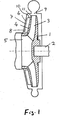
- einen axialen Schnitt durch die Pumpe als Ausschnitt,
- Fig. 2
- eine Ansicht der Außenseite des Laufrades mit den äußeren Schaufeln.
- Fig. 1
- an axial section through the pump as a cutout,
- Fig. 2
- a view of the outside of the impeller with the outer blades.
Das Laufrad 1 einer Radialkreiselpumpe sitzt auf einer Welle 2, die von einem
nicht dargestellten Elektromotor angetrieben wird. Die gebogenen inneren
Schaufeln 3 des Laufrades sind zu beiden Seiten abgedeckt. Auf der Vorderseite
bildet das Laufrad 1 eine ringförmige koaxiale Deckscheibe 4, in deren Mitte sich
die Saugöffnung 5 befindet.The impeller 1 of a radial centrifugal pump sits on a
Zwischen der Außenseite der Deckscheibe 4 und der Innenwand 6 des
Pumpengehäuses befindet sich ein Spalt 7, in dem äußere Schaufeln 8 liegen, die
an der Außenseite der Deckscheibe 4 befestigt insbesondere angeformt sind. Die
Schaufeln 8 sind so ausgerichtet und geformt, dass der von der Druckseite 9 zur
Saugseite fließende Rückstrom (Rückfluss) das Laufrad 1 zusätzlich antreibt.Between the outside of the
In einer Ausführung erstrecken sich die äußeren Schaufeln 8 vom Außenrand 11
bis zur Saugöffnung 5 des Laufrades. Alternativ können die äußeren Schaufeln 8
in einem Abstand vom Außenrand 11 des Laufrades 1 beginnen. Zusätzlich oder
alternativ können die äußeren Schaufeln 8 in einem Abstand zur Saugöffnung 5
des Laufrades 1 enden.In one embodiment, the
Die Anzahl der äußeren Schaufeln 8 kann unterschiedlich sein. Vorzugsweise sind
es ein bis acht Schaufeln. Die äußeren Schaufeln 8 können in ihrer Dicke von der
Saugseite zur Druckseite sich verändern oder auch eine gleichbleibende Dicke
besitzen. Die Eintrittskante 10 der äußeren Schaufeln 8 können einen
Nasenradius besitzen, der verdickt sein kann.The number of
Da die äußeren Schaufeln 8 eine Turbinenwirkung haben müssen, ist es wichtig,
dass die äußeren Schaufeln 8 entgegengesetzt gekrümmt sind zu den inneren
Laufradschaufeln 3.Since the
Claims (8)
Applications Claiming Priority (2)
| Application Number | Priority Date | Filing Date | Title |
|---|---|---|---|
| DE10307883 | 2003-02-25 | ||
| DE2003107883 DE10307883A1 (en) | 2003-02-25 | 2003-02-25 | Centrifugal pump, has external shovel on the circular coaxial cover disk forming a gap with the pump housing inner wall so that part of the conveyed liquid flows back to the suction face of the motor-wheel |
Publications (2)
| Publication Number | Publication Date |
|---|---|
| EP1457682A1 true EP1457682A1 (en) | 2004-09-15 |
| EP1457682B1 EP1457682B1 (en) | 2005-08-10 |
Family
ID=32748040
Family Applications (1)
| Application Number | Title | Priority Date | Filing Date |
|---|---|---|---|
| EP03027121A Expired - Lifetime EP1457682B1 (en) | 2003-02-25 | 2003-11-26 | Centrifugal pump |
Country Status (2)
| Country | Link |
|---|---|
| EP (1) | EP1457682B1 (en) |
| DE (2) | DE10307883A1 (en) |
Cited By (1)
| Publication number | Priority date | Publication date | Assignee | Title |
|---|---|---|---|---|
| DE102012201665A1 (en) * | 2012-02-06 | 2013-08-08 | Ksb Aktiengesellschaft | Centrifugal pump impeller has rear vanes that are connected to impeller hub section such that mass of rear vanes is increased from outer periphery of impeller main structure toward impeller hub |
Families Citing this family (2)
| Publication number | Priority date | Publication date | Assignee | Title |
|---|---|---|---|---|
| CN102052354B (en) * | 2010-12-07 | 2012-04-25 | 湖南耐普泵业有限公司 | High-speed multiphase flow gas-dissolving pump |
| DE202016008351U1 (en) | 2016-08-09 | 2017-10-09 | Fibre Optics Ct Gmbh, Consulting & Testing | Intruder alarm notification device |
Citations (4)
| Publication number | Priority date | Publication date | Assignee | Title |
|---|---|---|---|---|
| US4664592A (en) * | 1983-07-14 | 1987-05-12 | Warman International Limited | Centrifugal pump impeller configured to limit fluid recirculation |
| US4854820A (en) * | 1987-02-18 | 1989-08-08 | Zolotar Arkady I | Centrifugal pump for handling liquids carrying solid abrasive particles |
| US4883403A (en) * | 1986-10-07 | 1989-11-28 | Warman International Limited | Impellers for centrifugal pumps |
| WO2000071237A1 (en) * | 1999-05-25 | 2000-11-30 | Ferenc Inotay | Device for the mixing of liquid with gas and/or other liquids and/or granular, favourably powder-like material, and for the transportation of such mixtures |
Family Cites Families (4)
| Publication number | Priority date | Publication date | Assignee | Title |
|---|---|---|---|---|
| DE193313C (en) * | ||||
| US1879803A (en) * | 1930-01-27 | 1932-09-27 | Andrew G Johnson | Rotary pump |
| US2207317A (en) * | 1938-08-05 | 1940-07-09 | Glenn M Freeman | Centrifugal pump |
| DE1503248A1 (en) * | 1964-11-21 | 1969-05-08 | Alfa Romeo Societa Per Azioni | Impeller for rotating power and work machines |
-
2003
- 2003-02-25 DE DE2003107883 patent/DE10307883A1/en not_active Withdrawn
- 2003-11-26 DE DE50300951T patent/DE50300951D1/en not_active Expired - Lifetime
- 2003-11-26 EP EP03027121A patent/EP1457682B1/en not_active Expired - Lifetime
Patent Citations (4)
| Publication number | Priority date | Publication date | Assignee | Title |
|---|---|---|---|---|
| US4664592A (en) * | 1983-07-14 | 1987-05-12 | Warman International Limited | Centrifugal pump impeller configured to limit fluid recirculation |
| US4883403A (en) * | 1986-10-07 | 1989-11-28 | Warman International Limited | Impellers for centrifugal pumps |
| US4854820A (en) * | 1987-02-18 | 1989-08-08 | Zolotar Arkady I | Centrifugal pump for handling liquids carrying solid abrasive particles |
| WO2000071237A1 (en) * | 1999-05-25 | 2000-11-30 | Ferenc Inotay | Device for the mixing of liquid with gas and/or other liquids and/or granular, favourably powder-like material, and for the transportation of such mixtures |
Cited By (2)
| Publication number | Priority date | Publication date | Assignee | Title |
|---|---|---|---|---|
| DE102012201665A1 (en) * | 2012-02-06 | 2013-08-08 | Ksb Aktiengesellschaft | Centrifugal pump impeller has rear vanes that are connected to impeller hub section such that mass of rear vanes is increased from outer periphery of impeller main structure toward impeller hub |
| DE102012201665B4 (en) | 2012-02-06 | 2021-11-04 | KSB SE & Co. KGaA | Centrifugal pump impeller |
Also Published As
| Publication number | Publication date |
|---|---|
| DE10307883A1 (en) | 2004-09-02 |
| DE50300951D1 (en) | 2005-09-15 |
| EP1457682B1 (en) | 2005-08-10 |
Similar Documents
| Publication | Publication Date | Title |
|---|---|---|
| DE69620635T2 (en) | PUMP WHEEL WITH SEPARATED, SLITTED RODS | |
| EP2143954B1 (en) | Pump | |
| EP3374642B1 (en) | Electric axial-flow liquid pump for motor vehicle | |
| EP3224483B1 (en) | Centrifugal pump with guiding device | |
| DE102006035408B4 (en) | Impeller and fluid pump, which has the impeller | |
| DE6921197U (en) | IMPELLER FOR CENTRIFUGAL PUMPS | |
| DE3128372A1 (en) | "PERIPHERAL CHANNEL PUMP" | |
| EP1457682B1 (en) | Centrifugal pump | |
| EP0653564A1 (en) | Non-clogging centrifugal pump | |
| DE10307887A1 (en) | Centrifugal pump has blade whose region adjoining inlet edge has higher elasticity than remaining area in order to bend out from rest position through flow forces | |
| EP1039140B1 (en) | Feed pump | |
| EP1813819B1 (en) | Centrifugal Pump | |
| EP1053402B1 (en) | Centrifugal pump impeller having a radial structure | |
| WO2019110659A1 (en) | Impeller for wastewater pump | |
| DE102007025402A1 (en) | End shield for bearing a shaft | |
| EP3662164A1 (en) | Impeller for wastewater pump | |
| EP3559475A1 (en) | Vortex pump | |
| EP3728860B1 (en) | Side channel blower, in particular secondary air blower for an internal combustion engine | |
| DE1034031B (en) | Channel wheel, in particular single-channel wheel for centrifugal pumps to convey sludge-containing waste water | |
| DE102007025403B4 (en) | End shield for bearing a shaft | |
| DE200493C (en) | ||
| EP2205850A1 (en) | Fuel pump for delivering fuel from a reservoir to an internal combustion engine | |
| WO2008058639A1 (en) | Motor centrifugal pump | |
| EP0990799A1 (en) | Water coolant pump | |
| DE112005002258T5 (en) | Impeller with abradable tip |
Legal Events
| Date | Code | Title | Description |
|---|---|---|---|
| PUAI | Public reference made under article 153(3) epc to a published international application that has entered the european phase |
Free format text: ORIGINAL CODE: 0009012 |
|
| 17P | Request for examination filed |
Effective date: 20040517 |
|
| AK | Designated contracting states |
Kind code of ref document: A1 Designated state(s): AT BE BG CH CY CZ DE DK EE ES FI FR GB GR HU IE IT LI LU MC NL PT RO SE SI SK TR |
|
| AX | Request for extension of the european patent |
Extension state: AL LT LV MK |
|
| 17Q | First examination report despatched |
Effective date: 20041028 |
|
| GRAP | Despatch of communication of intention to grant a patent |
Free format text: ORIGINAL CODE: EPIDOSNIGR1 |
|
| GRAS | Grant fee paid |
Free format text: ORIGINAL CODE: EPIDOSNIGR3 |
|
| AKX | Designation fees paid |
Designated state(s): DE FR GB IT |
|
| GRAA | (expected) grant |
Free format text: ORIGINAL CODE: 0009210 |
|
| AK | Designated contracting states |
Kind code of ref document: B1 Designated state(s): DE FR GB IT |
|
| REG | Reference to a national code |
Ref country code: GB Ref legal event code: FG4D Free format text: NOT ENGLISH |
|
| REF | Corresponds to: |
Ref document number: 50300951 Country of ref document: DE Date of ref document: 20050915 Kind code of ref document: P |
|
| GBT | Gb: translation of ep patent filed (gb section 77(6)(a)/1977) |
Effective date: 20050917 |
|
| ET | Fr: translation filed | ||
| PLBE | No opposition filed within time limit |
Free format text: ORIGINAL CODE: 0009261 |
|
| STAA | Information on the status of an ep patent application or granted ep patent |
Free format text: STATUS: NO OPPOSITION FILED WITHIN TIME LIMIT |
|
| 26N | No opposition filed |
Effective date: 20060511 |
|
| PGFP | Annual fee paid to national office [announced via postgrant information from national office to epo] |
Ref country code: GB Payment date: 20141126 Year of fee payment: 12 |
|
| REG | Reference to a national code |
Ref country code: FR Ref legal event code: PLFP Year of fee payment: 13 |
|
| GBPC | Gb: european patent ceased through non-payment of renewal fee |
Effective date: 20151126 |
|
| REG | Reference to a national code |
Ref country code: FR Ref legal event code: PLFP Year of fee payment: 14 |
|
| PG25 | Lapsed in a contracting state [announced via postgrant information from national office to epo] |
Ref country code: GB Free format text: LAPSE BECAUSE OF NON-PAYMENT OF DUE FEES Effective date: 20151126 |
|
| REG | Reference to a national code |
Ref country code: FR Ref legal event code: PLFP Year of fee payment: 15 |
|
| REG | Reference to a national code |
Ref country code: FR Ref legal event code: PLFP Year of fee payment: 16 |
|
| PGFP | Annual fee paid to national office [announced via postgrant information from national office to epo] |
Ref country code: FR Payment date: 20221021 Year of fee payment: 20 |
|
| PGFP | Annual fee paid to national office [announced via postgrant information from national office to epo] |
Ref country code: IT Payment date: 20221020 Year of fee payment: 20 Ref country code: DE Payment date: 20221020 Year of fee payment: 20 |
|
| P01 | Opt-out of the competence of the unified patent court (upc) registered |
Effective date: 20230615 |
|
| REG | Reference to a national code |
Ref country code: DE Ref legal event code: R071 Ref document number: 50300951 Country of ref document: DE |