EP1457649A1 - Thermostat mounting structure - Google Patents
Thermostat mounting structure Download PDFInfo
- Publication number
- EP1457649A1 EP1457649A1 EP04004258A EP04004258A EP1457649A1 EP 1457649 A1 EP1457649 A1 EP 1457649A1 EP 04004258 A EP04004258 A EP 04004258A EP 04004258 A EP04004258 A EP 04004258A EP 1457649 A1 EP1457649 A1 EP 1457649A1
- Authority
- EP
- European Patent Office
- Prior art keywords
- thermostat
- aperture
- valve body
- mounting structure
- cover member
- Prior art date
- Legal status (The legal status is an assumption and is not a legal conclusion. Google has not performed a legal analysis and makes no representation as to the accuracy of the status listed.)
- Granted
Links
- 239000002826 coolant Substances 0.000 claims abstract description 45
- 230000002093 peripheral effect Effects 0.000 claims description 17
- 238000002485 combustion reaction Methods 0.000 description 16
- 230000013011 mating Effects 0.000 description 12
- XLYOFNOQVPJJNP-UHFFFAOYSA-N water Substances O XLYOFNOQVPJJNP-UHFFFAOYSA-N 0.000 description 6
- 238000001816 cooling Methods 0.000 description 4
- 238000005192 partition Methods 0.000 description 3
- 238000007789 sealing Methods 0.000 description 3
- 238000006243 chemical reaction Methods 0.000 description 2
- 230000003247 decreasing effect Effects 0.000 description 1
- 230000004941 influx Effects 0.000 description 1
- 230000037431 insertion Effects 0.000 description 1
- 238000003780 insertion Methods 0.000 description 1
- 239000000463 material Substances 0.000 description 1
- 230000002035 prolonged effect Effects 0.000 description 1
- 230000000630 rising effect Effects 0.000 description 1
- 238000011144 upstream manufacturing Methods 0.000 description 1
Images




Classifications
-
- G—PHYSICS
- G05—CONTROLLING; REGULATING
- G05D—SYSTEMS FOR CONTROLLING OR REGULATING NON-ELECTRIC VARIABLES
- G05D23/00—Control of temperature
- G05D23/01—Control of temperature without auxiliary power
- G05D23/13—Control of temperature without auxiliary power by varying the mixing ratio of two fluids having different temperatures
- G05D23/1306—Control of temperature without auxiliary power by varying the mixing ratio of two fluids having different temperatures for liquids
- G05D23/132—Control of temperature without auxiliary power by varying the mixing ratio of two fluids having different temperatures for liquids with temperature sensing element
- G05D23/1333—Control of temperature without auxiliary power by varying the mixing ratio of two fluids having different temperatures for liquids with temperature sensing element measuring the temperature of incoming fluid
-
- F—MECHANICAL ENGINEERING; LIGHTING; HEATING; WEAPONS; BLASTING
- F16—ENGINEERING ELEMENTS AND UNITS; GENERAL MEASURES FOR PRODUCING AND MAINTAINING EFFECTIVE FUNCTIONING OF MACHINES OR INSTALLATIONS; THERMAL INSULATION IN GENERAL
- F16L—PIPES; JOINTS OR FITTINGS FOR PIPES; SUPPORTS FOR PIPES, CABLES OR PROTECTIVE TUBING; MEANS FOR THERMAL INSULATION IN GENERAL
- F16L23/00—Flanged joints
- F16L23/02—Flanged joints the flanges being connected by members tensioned axially
- F16L23/032—Flanged joints the flanges being connected by members tensioned axially characterised by the shape or composition of the flanges
-
- F—MECHANICAL ENGINEERING; LIGHTING; HEATING; WEAPONS; BLASTING
- F01—MACHINES OR ENGINES IN GENERAL; ENGINE PLANTS IN GENERAL; STEAM ENGINES
- F01P—COOLING OF MACHINES OR ENGINES IN GENERAL; COOLING OF INTERNAL-COMBUSTION ENGINES
- F01P7/00—Controlling of coolant flow
- F01P7/14—Controlling of coolant flow the coolant being liquid
- F01P7/16—Controlling of coolant flow the coolant being liquid by thermostatic control
-
- F—MECHANICAL ENGINEERING; LIGHTING; HEATING; WEAPONS; BLASTING
- F16—ENGINEERING ELEMENTS AND UNITS; GENERAL MEASURES FOR PRODUCING AND MAINTAINING EFFECTIVE FUNCTIONING OF MACHINES OR INSTALLATIONS; THERMAL INSULATION IN GENERAL
- F16L—PIPES; JOINTS OR FITTINGS FOR PIPES; SUPPORTS FOR PIPES, CABLES OR PROTECTIVE TUBING; MEANS FOR THERMAL INSULATION IN GENERAL
- F16L23/00—Flanged joints
- F16L23/16—Flanged joints characterised by the sealing means
- F16L23/18—Flanged joints characterised by the sealing means the sealing means being rings
- F16L23/22—Flanged joints characterised by the sealing means the sealing means being rings made exclusively of a material other than metal
-
- F—MECHANICAL ENGINEERING; LIGHTING; HEATING; WEAPONS; BLASTING
- F16—ENGINEERING ELEMENTS AND UNITS; GENERAL MEASURES FOR PRODUCING AND MAINTAINING EFFECTIVE FUNCTIONING OF MACHINES OR INSTALLATIONS; THERMAL INSULATION IN GENERAL
- F16L—PIPES; JOINTS OR FITTINGS FOR PIPES; SUPPORTS FOR PIPES, CABLES OR PROTECTIVE TUBING; MEANS FOR THERMAL INSULATION IN GENERAL
- F16L43/00—Bends; Siphons
- F16L43/001—Bends; Siphons made of metal
-
- F—MECHANICAL ENGINEERING; LIGHTING; HEATING; WEAPONS; BLASTING
- F16—ENGINEERING ELEMENTS AND UNITS; GENERAL MEASURES FOR PRODUCING AND MAINTAINING EFFECTIVE FUNCTIONING OF MACHINES OR INSTALLATIONS; THERMAL INSULATION IN GENERAL
- F16L—PIPES; JOINTS OR FITTINGS FOR PIPES; SUPPORTS FOR PIPES, CABLES OR PROTECTIVE TUBING; MEANS FOR THERMAL INSULATION IN GENERAL
- F16L43/00—Bends; Siphons
- F16L43/008—Bends; Siphons made from plastic material
-
- F—MECHANICAL ENGINEERING; LIGHTING; HEATING; WEAPONS; BLASTING
- F01—MACHINES OR ENGINES IN GENERAL; ENGINE PLANTS IN GENERAL; STEAM ENGINES
- F01P—COOLING OF MACHINES OR ENGINES IN GENERAL; COOLING OF INTERNAL-COMBUSTION ENGINES
- F01P2070/00—Details
Definitions
- the present invention relates to a mounting structure of a thermostat to control a flow of coolant in a cooling system of an internal combustion engine.
- thermostat is placed in an embedding hole that is formed across a coolant channel of a casing.
- a cover member covers the embedding hole via a rubber seal and fixes the thermostat.
- An embedding hole 03 is formed across a coolant channel 02 in a casing 01.
- a thermostat 07 is placed in the embedding hole 03.
- a cover member 05 covers the embedding hole 03 via a rubber seal 04 and fixes the thermostat 07.
- the thermostat 07 has an entry aperture 08a and an exit aperture 08b on a surrounding wall of a cylindrical valve body 08.
- a valving element 09 advances and retracts to open and close the apertures 08a and 08b.
- the thermostat 07 is placed in the embedding hole 03 so that both apertures 08a and 08b face to the coolant channel 02 in the casing 01.
- a by-pass aperture 08c is provided below the exit aperture 08b to connect an inside space of the valve body 08 with the coolant channel 02.
- the exit aperture 08b and the by-pass aperture 08c are opened selectively.
- the thermostat 07 is surrounded with an O-ring 011 that partitions an outer peripheral surface of the valve body 08 into a side of the entry aperture 08a and a side of the exit aperture 08b.
- the cover member 05 has a by-pass channel 06 and is embedded with the rubber seal 04 in a circular groove.
- the cover member 05 is attached to the casing 01 via the rubber seal 04 so as to cover the embedding hole of the casing engaged with the thermostat 07.
- the rubber seal 04 is pressed to an aperture end of the embedding hole in the casing and over to an aperture end of the cylindrical valve body 08 to fix the thermostat 07.
- the O-ring 011 allows the outside space of the valve body 08 of the thermostat 07 to divide the inside of the embedding hole 03 of the casing 01 into halves, i.e., influx and efflux sides.
- the rubber seal 04 divides the valve body 08 into inside and outside spaces inside the embedding hole 03 of the casing 01.
- the above-mentioned conventional structure has an advantage of compactly conf iguring a thermostat unit.
- the thermostat 07 is supported by the O-ring 011 in a floating manner. No positioning structure is provided to the rubber seal 04 and the casing 01. This causes slight misalignment to the thermostat 07 after assembly.
- the present invention has been made in consideration of the foregoing. It is therefore an object of the present invention to provide a simply structured thermostat mounting structure capable of reliably positioning an embedded thermostat and ensuring high sealability.
- the present invention provides a thermostat mounting structure, wherein a coolant channel is formed in a casing; wherein an embedding hole is formed in the casing across the coolant channel; wherein there is provided a thermostat comprising a cylindrical valve body whose surrounding wall has an entry aperture and an exit aperture; wherein a valving element advances and retracts to open and close both apertures; wherein the thermostat is inserted into the embedding hole so that both apertures face the coolant channel; wherein a cover member covers the embedding hole via a circular rubber seal seated in a groove of the cover member and fixes the thermostat; and wherein there is provided a positioning structure to position the thermostat to a side of the cover member.
- the cover member is attached to the casing by covering the embedding hole.
- the positioning structure provided for the cover member positions and fixes the thermostat inserted into the casing's embedding hole. It is possible to reliably prevent the thermostat against misalignment by using the simple structure and ensure high sealabilityusing the rubber seal.
- the present invention according to claim 2 provides the thermostat mounting structure according to claim 1, wherein the positioning structure positions the thermostat by engagedly supporting an aperture end of the cylindrical valve body.
- the rubber seal seals the aperture end of the valve body.
- the aperture end is engagedly supported for thermostat positioning, ensuring more reliable sealing.
- the present invention according to claim 3 provides the thermostat mounting structure according to claim 2, wherein the positioning structure positions the thermostat by inserting a joint into an inside periphery of an aperture end of the cylindrical valve body.
- the joint for the cover member is inserted into the inside periphery of the cylindrical valve body's aperture end for thermostat positioning. Reliable positioning is available under no influence of coolant pressure.
- the present invention according to claim 4 provides the thermostat mounting structure according to claim 3, wherein the joint is a circular rib; and wherein the rib is inserted along an inner peripheral surface of an aperture end of the cylindrical valve body to position the thermostat.
- the circular rib is inserted along the inner peripheral surface of the valve body's aperture end for positioning. It is possible to configure the positioning structure capable of relieving a stress.
- the present invention according to claim 5 provides the thermostat mounting structure according any one of claims 2 through 4, wherein the positioning structure is formed on the cover member.
- the rubbermember engagedly supports the rubber seal to eliminate misalignment between the rubber seal's seal portion and the positioned thermostat. Consequently, the sealability further improves.
- thermostat according to the embodiment is represented as an embedded thermostat 50 applied to an internal combustion engine's cooling system.
- a cam shaft 2 is rotatively supported on a cylinder head 1.
- a driven sprocket 3 is tightened to an end of the cam shaft 2.
- a timing chain 4 is looped around the driven sprocket 3. The other end of the timing chain 4 is looped around a driving sprocket fit to a crank shaft (not shown).
- the timing chain 4 halves the number of revolutions of the crank shaft and transmits the revolution to the cam shaft 2.
- the timing chain 4 is provided in a chain chamber 1a formed in the cylinder head 1.
- a side wall forming the chain chamber 1a is provided with an aperture coaxial with the cam shaft 2.
- a pump body case 6 is inserted into the aperture.
- a water pump 5 is placed in the pump body case 6.
- the pump body case 6 for the water pump 5 comprises a bottomed cylinder section 6a and a large aperture section 6b.
- the bottomed cylinder section 6a contains a driven magnet 8 supported by a rotating shaft 7.
- the large aperture section 6b contains an impeller 9 fit to the rotating shaft 7.
- a pump cover case 20 covers the large aperture section 6b and axially supports one end of the rotating shaft 7 to rotatively support the driven magnet 8 and the impeller 9.
- a driving magnet 11 is provided around the pump body case 6 inserted into the chain chamber 1a of the cylinder head 1.
- the driving magnet 11 is fit to an inner peripheral surface of the cylindrical support member 10 tightened with the driven sprocket 3 at the end of the cam shaft 2.
- the driving magnet 11 rotates with the cam shaft 2 to subsequently rotate the driven magnet 8 of the water pump 5 separated by the pump body case 6 and to rotate the impeller 9.
- the pump cover case 20 is fit into the large aperture section 6b of the pump body case 6 and has a protruding annular rib 22 constituting a scroll chamber 21 in which the impeller 9 rotates.
- Abearing section 23 of the rotating shaft 7 protrudes at the center of the pump cover case 20 (see FIGS. 1 and 3).
- the pump cover case 20 is also used as a thermostat case and has a mating face 24 with the thermostat cover 30 at the opposite side of the scroll chamber 21.
- a thermostat chamber 25 is largely bored into the mating face 24 so as to be used as an embedding hole for the thermostat 50.
- the thermostat 50 is inserted into the thermostat chamber 25.
- the mating face 24 with the thermostat cover 30 has screw holes 24a in approximately opposite directions along an extension from the thermostat chamber 25.
- the thermostat chamber 25 forms a slightly tapered inner peripheral surface 25a having a gradually decreasing inside diameter from the mating face 24.
- the innermost part forms an approximate hemispheric surface 25b.
- a slot 25c is partly formed on the tapered inner peripheral surface 25a from the aperture end to the innermost.
- a coolant suction channel 26 opens against the inner tapered surface of the thermostat chamber 25 and is formed orthogonally to the thermostat chamber 25.
- An upstream side portion of the coolant suction channel 26 protrudes as a suction connection pipe 27.
- the other downstream portion leads to an annular suction channel 26a formed along an outside periphery of the bearing section 23. That is to say, the thermostat chamber 25 is formed across the coolant suction channel 26.
- An exhaust connection pipe 28 protrudes parallel to the suction connection pipe 27 and forms a coolant exhaust channel 29 as shown in FIG. 4.
- the coolant exhaust channel 29 leads to the scroll chamber 21 formed externally around the impeller 9.
- the thermostat 50 is inserted into the thermostat chamber 25 of the pump cover case 20 and is structured as shown in FIGS. 10 through 14. There are formed an entry aperture 52 and an exit aperture 53 on a surrounding wall of the slightly tapered cylindrical valve body 51. These apertures are rectangular and are opposite to each other. Further, a by-pass aperture 54 is formed below the exit aperture 53.
- valve body 51 One end of the valve body 51 forms an annular aperture end 51a.
- the other end forms a bottom wall 51b.
- a bottomed cylinder section 55 having a small diameter protrudes from the center of the bottom wall 51b.
- Ribs 56 extend from the bottomed cylinder section 55 to both sides leading to the bottom wall 51b. Each end of the ribs 56 is curved to smoothly make the same surface as the external surface of the valve body 51, forming the same curved surface as the hemispheric surface 25b at the innermost of the thermostat chamber 25.
- the bottomed cylinder section 55 and the ribs 56 are formed integrally with the valve body 51.
- the ribs 56 are formed along a flat surface including the center axis of the valve body 51 at the middle between the entry aperture 52 and the exit aperture 53 of the valve body 51.
- the slot 57 is formed continuously along a line of intersection between a flat surface corresponding to the ridge line center of the ribs 56 including the center axis of the valve body 51 and the end of the ribs 56, the end of the bottomed cylinder section 55, the outer peripheral surface of the valve body 51, and the aperture end 51a of the valve body 51.
- a rubber O-ring 58 is fit into the slot 57.
- the O-ring 58 rises from the slot 57 to halve the outside periphery of the valve body 51 into the side of the entry aperture 52 and the side of the exit aperture 53.
- a protruded piece 59 is formed near the aperture end 51a below the by-pass aperture 54 on the outer peripheral surface of the valve body 51.
- a valving element 61 is slidably inserted into a columnar inside space 60 of the valve body 51.
- a small-diameter cylinder section 61a extends from the valving element 61 and is slidably inserted into the bottomed cylinder section 55.
- a hollowed surface is formed opposite the small-diameter cylinder section 61a of the valving element 61 to form a concave portion. The concave portion continues to the inside space of the small-diameter cylinder section 61a.
- a bottomed cylindrical wax case 62 is fastened to the valving element 61 via a diaphragm 63 by caulking the aperture edge so as to cover the concave portion of the valving element 61.
- the wax case 62 contains a wax 64 as a thermal expansion material.
- a semifluid 65 is filled in the concave portion of the valving element 61 on the other side of the diaphragm 63.
- a piston 68 is slidably inserted into the inside space of the small-diameter cylinder section 61a via a rubber piston 66 contacting the semifluid 65 and a backup plate 67.
- a C-ring 69 is fit into a circumferentially opening slot near the aperture end 51a on the inner peripheral surface of the valve body 51.
- a spring 70 is inserted between the C-ring 69 and the valving element 61 to press the valving element 61 against the bottom wall 51b of the valve body 51.
- a force applied by the spring 70 allows the valving element 61 to touch the bottom wall 51b to close the entry aperture 52 and the exit aperture 53. At this time, the by-pass aperture 54 opens.
- the piston 68 is stationed to a specified position always incontactwith thebottomof the bottomed cylinder section 55.
- the valving element 61 moves against the spring 70 to open the entry aperture 52 and the exit aperture 53 as shown in FIG. 16 so that both apertures can communicate with each other.
- the by-pass aperture 54 closes.
- the above-mentioned thermostat 50 is inserted into the thermostat chamber 25 of the pump cover case 20.
- the protruded piece 59 outside the valve body 51 is inserted into the slot 25c on the inside periphery of the thermostat chamber 25. This enables positioning along the rotative direction around the center axis of the valve body 51.
- the entry aperture 52 and the exit aperture 53 face to the coolant suction channel 26.
- the by-pass aperture 54 faces to the coolant suction channel 26 like the exit aperture 53.
- the O-ring 58 provided around the valve body 51 is pressed by the inner peripheral surface 25a and the hemispheric surface 25b of the thermostat chamber 25. Consequently, the O-ring 58 partitions a space between the inner peripheral surface 25a and the valve body 51 into the side of the entry aperture 52 and the side of the exit aperture 53 together with the ribs 56 of the thermostat 50.
- the thermostat cover 30 covers the aperture of the thermostat chamber 25 inserted with the thermostat 50. As shown in FIGS. 5 through 7, the thermostat cover 30 is provided with a coaxial circular outer wall 32 and a slightly higher inner circular rib 33 vertically on a mating face 31 corresponding to the mating face 24 of the pump cover case 20. A circular groove 34 is formed between the outer wall 32 and the inner circular rib 33. A concave portion 35 is formed inside the inner circular rib 33.
- a by-pass channel 36a connects to the concave portion 35 and comprises a by-pass pipe 36 that extends to one side.
- a connection pipe 37 is pressed into the by-pass pipe 36.
- the mating face 31 comprises an end face of the outer wall 32 and end faces of extended sections 38 and 39 that extend sideways.
- the extended sections 38 and 39 have mounting holes 38a and 39a.
- the inner circular rib 33 is higher than the outer wall 32 and protrudes from the mating face 31.
- An outside diameter of the inner circular rib 33 equals an inside diameter of the aperture end 51a of the valve body 51 in the thermostat 50.
- the inner circular rib 33 can be inserted into the valve body 51 along the inner peripheral surface 51a.
- a pair of notches 33a are formed opposite to each other at specified positions on an edge of the inner circular rib 33.
- the width between the notches corresponds to the diameter of the O-ring 58 provided around the valve body 51 in the thermostat 50.
- the depth of the notches 33a is approximately equals the protrusion of the mating face 31 from the inner circular rib 33.
- the bottom of each of the rounded notches 33a almost levels the mating face 31 (see FIG. 7).
- a circular rubber seal 40 is fit into the circular groove 34 between the inner circular rib 33 and the outer wall 32.
- FIGS. 8 and 9 illustrate the shape of the rubber seal 40.
- the rubber seal 40 is circular andhas a rectangular section.
- Protruded pieces 41 and 42 are formed along outer and inner peripheries on one side of the rubber seal 40.
- a protruded piece 43 is formed along an outer periphery on the other side thereof. Small slots are formed along the protruded piece 41, 42, and 43.
- the rubber seal 40 is fit into the circular groove 34 of the thermostat cover 30.
- the thermostat cover 30 can be aligned so as to cover the thermostat chamber 25 of the pump cover case 20 inserted with the thermostat 50.
- the inner circular rib 33 protruding from the mating face 31 of the thermostat cover 30 is inserted into the thermostat 50 along the inner peripheral surface at the aperture end of the valve body 51.
- the thermostat 50 can be centered with a simple structure.
- the O-ring 58 around the valve body 51 crosses at the aperture end of the valve body 51 along the diametric direction.
- the O-ring 58 is fit into the pair of notches 33a formed on the edge of the inner circular rib 33.
- the inner circular rib 33 can be attached without being obstructed by the O-ring 58.
- the rubber seal 40 is pressed across the mating face 24 around the thermostat chamber 25 and the aperture end 21a of the valve body 21 in the thermostat 50. In this manner, the rubber seal 40 seals the inside space 60 of the valve body 21 from the outside space.
- the inner circular rib 33 is inserted into the aperture end of the valve body 51 in the thermostat 50 to accurately and reliably center the thermostat 50. Accordingly, it is possible to reliably protect the valve body 21 against misalignment and improve the sealability.
- the thermostat cover 30 is fit to the pump cover case 20. Two bolts 80 are inserted into the mounting holes 38a and 39a of the thermostat cover 30 and are screwed into screw holes 24a of the pump cover case 20. In this manner, the thermostat 30 is attached to the pump cover case 20 to house the thermostat 50.
- the O-ring 58 is provided around the valve body 51.
- the O-ring 58 is pressed against the inner peripheral surface 25a and the hemispheric surface 25b of the thermostat chamber 25. Further, the O-ring 58 is sandwiched between the aperture end 21a of the valve body 21 and the rubber seal 40. In this manner, the O-ring 58 completely partitions the inner peripheral surface 25a of the thermostat chamber 25, the valve body 51, and gaps into the side of the entry aperture 52 and the side of the exit aperture 53 for sealing.
- the rubber seal 40 separates the inside space 60 of the valve body 21 from the outside space, i.e., a gap space between the thermostat 50 and the thermostat chamber 25 for sealing.
- the coolant supplied from the water pump 5 flows into the internal combustion engine E.
- the coolant from the internal combustion engine E flows into the radiator R.
- the coolant supplied from the radiator R passes through the coolant suction channel 26 of the pump cover case 20 and flows into the entry aperture 52 of the thermostat 50.
- the coolant from the internal combustion engine E passes through the by-pass channel 36a and flows into the inside space 60 of the thermostat 50.
- the low-temperature coolant before warm-up circulates through the cooling system.
- the low temperature is transmitted from the coolant to the wax 64 in the thermostat 50 via the valving element 61 and the wax case 62.
- the valving element 61 closes entry aperture 52 and the exit aperture 53 and opens the by-pass aperture 54.
- the coolant After the coolant is supplied from the water pump 5 and circulates through the internal combustion engine E tobe heated, the coolant flows through a by-pass circulation path from the by-pass channel 36a to the inside space 60 of the thermostat 50, through the by-pass aperture 54, then to the weather pump 5 as shown in FIG. 15.
- the circulating coolant With the lapse of time, the circulating coolant is heated.
- the wax 64 in the wax case 62 of the thermostat 50 thermally expands to increase its volume. Consequently, an expansive force is applied to push the piston 68 out of the small-diameter cylinder section 61a.
- the valving element 61 moves against the spring 70 to open the entry aperture 52 and the exit aperture 53 as shown in FIG. 16 to communicate with each other.
- the by-pass aperture 54 closes.
- the coolant is supplied from the water pump 5, circulates through the internal combustion engine E to be heated, and flows into the radiator R.
- the coolant follows the circulation path so that is cooled in the radiator R, passes through the communicating apertures, i.e., the entry aperture 52 and the exit aperture 53 of the thermostat 50, and then is absorbed in the waterpump 5. In this manner, the internal combustion engine E is cooled.
- the thermostat 50 has such a mounting structure that the inner circular rib 33 of the thermostat cover 30 is inserted along the inner peripheral surface at the aperture end of the valve body 51 for the thermostat 50. Consequently, the thermostat 50 is positioned accurately and reliably, thus ensuring high sealability. This structure almost completely prevents the coolant passing through the radiator R from leaking out to the circulation path through the internal combustion engine and can solve the problem of prolonged warm-up time.
- the invention provides a simply structured thermostat mounting structure capable of reliably positioning an embedded thermostat and ensuring high sealability.
- thermostat mounting structure as follows.
- a coolant channel 26 is formed in a casing 20.
- An embedding hole 25 is formed in the casing 20 across the coolant channel 26.
- a thermostat 50 comprising a cylindrical valve body 51 whose surrounding wall has an entry aperture 52 and an exit aperture 53.
- a valving element advances and retracts to open and close both apertures 52 and 53.
- the thermostat 50 is inserted into the embedding hole 25 so that both apertures 52 and 53 face the coolant channel 26.
- a cover member 30 covers the embedding hole 25 via a circular rubber seal 40 seated in a groove of the cover member 30 and fixes the thermostat 50.
- a positioning structure 33 to position the thermostat 50 to a side of the cover member 30.
Landscapes
- Engineering & Computer Science (AREA)
- General Engineering & Computer Science (AREA)
- Mechanical Engineering (AREA)
- Physics & Mathematics (AREA)
- General Physics & Mathematics (AREA)
- Automation & Control Theory (AREA)
- Chemical & Material Sciences (AREA)
- Combustion & Propulsion (AREA)
- Temperature-Responsive Valves (AREA)
Abstract
Description
- The present invention relates to a mounting structure of a thermostat to control a flow of coolant in a cooling system of an internal combustion engine.
- There is already proposed a mounting structure for an embedded thermostat (Jp-A-39433/2002, 2nd emb.). According to the structure, the thermostat is placed in an embedding hole that is formed across a coolant channel of a casing. A cover member covers the embedding hole via a rubber seal and fixes the thermostat.
- Referring now to FIG. 17, the following describes the mounting structure for the embedded thermostat disclosed in the second embodiment of
patent document 1. - An
embedding hole 03 is formed across acoolant channel 02 in acasing 01. Athermostat 07 is placed in theembedding hole 03. Acover member 05 covers theembedding hole 03 via arubber seal 04 and fixes thethermostat 07. - The
thermostat 07 has anentry aperture 08a and anexit aperture 08b on a surrounding wall of acylindrical valve body 08. A valvingelement 09 advances and retracts to open and close theapertures thermostat 07 is placed in theembedding hole 03 so that bothapertures coolant channel 02 in thecasing 01. - A by-
pass aperture 08c is provided below theexit aperture 08b to connect an inside space of thevalve body 08 with thecoolant channel 02. When thevalving element 09 advances and retracts due to thermal expansion ofwax 010, theexit aperture 08b and the by-pass aperture 08c are opened selectively.
Thethermostat 07 is surrounded with an O-ring 011 that partitions an outer peripheral surface of thevalve body 08 into a side of theentry aperture 08a and a side of theexit aperture 08b. - The
cover member 05 has a by-pass channel 06 and is embedded with therubber seal 04 in a circular groove. Thecover member 05 is attached to thecasing 01 via therubber seal 04 so as to cover the embedding hole of the casing engaged with thethermostat 07. - The
rubber seal 04 is pressed to an aperture end of the embedding hole in the casing and over to an aperture end of thecylindrical valve body 08 to fix thethermostat 07. - Accordingly, the O-
ring 011 allows the outside space of thevalve body 08 of thethermostat 07 to divide the inside of theembedding hole 03 of thecasing 01 into halves, i.e., influx and efflux sides. Therubber seal 04 divides thevalve body 08 into inside and outside spaces inside theembedding hole 03 of thecasing 01. - The above-mentioned conventional structure has an advantage of compactly conf iguring a thermostat unit. However, the
thermostat 07 is supported by the O-ring 011 in a floating manner. No positioning structure is provided to therubber seal 04 and thecasing 01. This causes slight misalignment to thethermostat 07 after assembly. - The present invention has been made in consideration of the foregoing. It is therefore an object of the present invention to provide a simply structured thermostat mounting structure capable of reliably positioning an embedded thermostat and ensuring high sealability.
- In order to achieve the above-mentioned object, the present invention according to
claim 1 provides a thermostat mounting structure, wherein a coolant channel is formed in a casing; wherein an embedding hole is formed in the casing across the coolant channel; wherein there is provided a thermostat comprising a cylindrical valve body whose surrounding wall has an entry aperture and an exit aperture; wherein a valving element advances and retracts to open and close both apertures; wherein the thermostat is inserted into the embedding hole so that both apertures face the coolant channel; wherein a cover member covers the embedding hole via a circular rubber seal seated in a groove of the cover member and fixes the thermostat; and wherein there is provided a positioning structure to position the thermostat to a side of the cover member. - The cover member is attached to the casing by covering the embedding hole. At this time, the positioning structure provided for the cover member positions and fixes the thermostat inserted into the casing's embedding hole. It is possible to reliably prevent the thermostat against misalignment by using the simple structure and ensure high sealabilityusing the rubber seal.
- The present invention according to
claim 2 provides the thermostat mounting structure according toclaim 1, wherein the positioning structure positions the thermostat by engagedly supporting an aperture end of the cylindrical valve body. - The rubber seal seals the aperture end of the valve body. The aperture end is engagedly supported for thermostat positioning, ensuring more reliable sealing.
- The present invention according to
claim 3 provides the thermostat mounting structure according toclaim 2, wherein the positioning structure positions the thermostat by inserting a joint into an inside periphery of an aperture end of the cylindrical valve body. - The joint for the cover member is inserted into the inside periphery of the cylindrical valve body's aperture end for thermostat positioning. Reliable positioning is available under no influence of coolant pressure.
- The present invention according to claim 4 provides the thermostat mounting structure according to
claim 3, wherein the joint is a circular rib; and wherein the rib is inserted along an inner peripheral surface of an aperture end of the cylindrical valve body to position the thermostat. - The circular rib is inserted along the inner peripheral surface of the valve body's aperture end for positioning. It is possible to configure the positioning structure capable of relieving a stress.
- The present invention according to claim 5 provides the thermostat mounting structure according any one of
claims 2 through 4, wherein the positioning structure is formed on the cover member. - Since the positioning structure is formed on the cover member, no extra positioning member is needed, eliminating the number of parts. The rubbermember engagedly supports the rubber seal to eliminate misalignment between the rubber seal's seal portion and the positioned thermostat. Consequently, the sealability further improves.
- FIG. 1 is a partial sectional view showing a mounting structure of an embedded thermostat according to an embodiment of the present invention applied to a cooling system of an internal combustion engine and showing part of the internal combustion engine;
- FIG. 2 is a side view of a pump cover case;
- FIG. 3 is a sectional view taken along lines III-III of FIG. 2;
- FIG. 4 is a sectional view taken along lines IV-IV of FIG. 2;
- FIG. 5 is a side view of a thermostat cover;
- FIG. 6 shows a rear view of the thermostat cover;
- FIG. 7 is a sectional view taken along lines VII-VII of FIG. 6;
- FIG. 8 is a plan view of a rubber seal;
- FIG. 9 is a sectional view taken along lines IX-IX of FIG. 8;
- FIG. 10 is a front view of a thermostat;
- FIG. 11 is a side view of the thermostat;
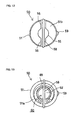
- FIG. 12 is a top view of the thermostat;
- FIG. 13 is a bottom view of the thermostat;
- FIG. 14 is a sectional view taken along lines XIV-XIV of FIG. 11;
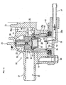
- FIG. 15 is an enlarged sectional view showing the mounting structure when the thermostat is set to a low temperature;
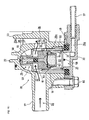
- FIG. 16 is an enlarged sectional view showing the mounting structure when the thermostat is set to a high temperature; and
- FIG. 17 is a sectional view showing a mounting structure of a conventional thermostat.
-
- An embodiment of the present invention will be described in further detail with reference to FIGS. 1 through 16.
The thermostat according to the embodiment is represented as an embeddedthermostat 50 applied to an internal combustion engine's cooling system. - As shown in FIG. 1, a
cam shaft 2 is rotatively supported on acylinder head 1. A drivensprocket 3 is tightened to an end of thecam shaft 2. A timing chain 4 is looped around the drivensprocket 3. The other end of the timing chain 4 is looped around a driving sprocket fit to a crank shaft (not shown). The timing chain 4 halves the number of revolutions of the crank shaft and transmits the revolution to thecam shaft 2. - The timing chain 4 is provided in a chain chamber 1a formed in the
cylinder head 1. A side wall forming the chain chamber 1a is provided with an aperture coaxial with thecam shaft 2. Apump body case 6 is inserted into the aperture. A water pump 5 is placed in thepump body case 6. - The
pump body case 6 for the water pump 5 comprises a bottomedcylinder section 6a and alarge aperture section 6b. The bottomedcylinder section 6a contains a driven magnet 8 supported by a rotating shaft 7. Thelarge aperture section 6b contains an impeller 9 fit to the rotating shaft 7. Apump cover case 20 covers thelarge aperture section 6b and axially supports one end of the rotating shaft 7 to rotatively support the driven magnet 8 and the impeller 9. - A driving magnet 11 is provided around the
pump body case 6 inserted into the chain chamber 1a of thecylinder head 1. The driving magnet 11 is fit to an inner peripheral surface of thecylindrical support member 10 tightened with the drivensprocket 3 at the end of thecam shaft 2. The driving magnet 11 rotates with thecam shaft 2 to subsequently rotate the driven magnet 8 of the water pump 5 separated by thepump body case 6 and to rotate the impeller 9. - The
pump cover case 20 is fit into thelarge aperture section 6b of thepump body case 6 and has a protrudingannular rib 22 constituting ascroll chamber 21 in which the impeller 9 rotates.Abearing section 23 of the rotating shaft 7 protrudes at the center of the pump cover case 20 (see FIGS. 1 and 3). - As shown in FIGS. 2 through 4, the
pump cover case 20 is also used as a thermostat case and has amating face 24 with thethermostat cover 30 at the opposite side of thescroll chamber 21. Athermostat chamber 25 is largely bored into themating face 24 so as to be used as an embedding hole for thethermostat 50. Thethermostat 50 is inserted into thethermostat chamber 25. - The
mating face 24 with thethermostat cover 30 hasscrew holes 24a in approximately opposite directions along an extension from thethermostat chamber 25. - The
thermostat chamber 25 forms a slightly tapered innerperipheral surface 25a having a gradually decreasing inside diameter from themating face 24. The innermost part forms an approximatehemispheric surface 25b.
Aslot 25c is partly formed on the tapered innerperipheral surface 25a from the aperture end to the innermost. - A
coolant suction channel 26 opens against the inner tapered surface of thethermostat chamber 25 and is formed orthogonally to thethermostat chamber 25. An upstream side portion of thecoolant suction channel 26 protrudes as asuction connection pipe 27. The other downstream portion leads to anannular suction channel 26a formed along an outside periphery of thebearing section 23.
That is to say, thethermostat chamber 25 is formed across thecoolant suction channel 26. - An
exhaust connection pipe 28 protrudes parallel to thesuction connection pipe 27 and forms acoolant exhaust channel 29 as shown in FIG. 4. Thecoolant exhaust channel 29 leads to thescroll chamber 21 formed externally around the impeller 9. - The
thermostat 50 is inserted into thethermostat chamber 25 of thepump cover case 20 and is structured as shown in FIGS. 10 through 14. There are formed anentry aperture 52 and anexit aperture 53 on a surrounding wall of the slightly taperedcylindrical valve body 51. These apertures are rectangular and are opposite to each other. Further, a by-pass aperture 54 is formed below theexit aperture 53. - One end of the
valve body 51 forms anannular aperture end 51a. The other end forms abottom wall 51b. A bottomedcylinder section 55 having a small diameter protrudes from the center of thebottom wall 51b. -
Ribs 56 extend from the bottomedcylinder section 55 to both sides leading to thebottom wall 51b. Each end of theribs 56 is curved to smoothly make the same surface as the external surface of thevalve body 51, forming the same curved surface as thehemispheric surface 25b at the innermost of thethermostat chamber 25. - The bottomed
cylinder section 55 and theribs 56 are formed integrally with thevalve body 51. Theribs 56 are formed along a flat surface including the center axis of thevalve body 51 at the middle between theentry aperture 52 and theexit aperture 53 of thevalve body 51. - The
slot 57 is formed continuously along a line of intersection between a flat surface corresponding to the ridge line center of theribs 56 including the center axis of thevalve body 51 and the end of theribs 56, the end of the bottomedcylinder section 55, the outer peripheral surface of thevalve body 51, and theaperture end 51a of thevalve body 51. A rubber O-ring 58 is fit into theslot 57. - The O-
ring 58 rises from theslot 57 to halve the outside periphery of thevalve body 51 into the side of theentry aperture 52 and the side of theexit aperture 53.
A protrudedpiece 59 is formed near theaperture end 51a below the by-pass aperture 54 on the outer peripheral surface of thevalve body 51. - A
valving element 61 is slidably inserted into a columnar insidespace 60 of thevalve body 51. A small-diameter cylinder section 61a extends from thevalving element 61 and is slidably inserted into the bottomedcylinder section 55.
A hollowed surface is formed opposite the small-diameter cylinder section 61a of thevalving element 61 to form a concave portion. The concave portion continues to the inside space of the small-diameter cylinder section 61a. - A bottomed
cylindrical wax case 62 is fastened to thevalving element 61 via adiaphragm 63 by caulking the aperture edge so as to cover the concave portion of thevalving element 61. Thewax case 62 contains awax 64 as a thermal expansion material. A semifluid 65 is filled in the concave portion of thevalving element 61 on the other side of thediaphragm 63. - A
piston 68 is slidably inserted into the inside space of the small-diameter cylinder section 61a via arubber piston 66 contacting the semifluid 65 and abackup plate 67.
A C-ring 69 is fit into a circumferentially opening slot near theaperture end 51a on the inner peripheral surface of thevalve body 51. Aspring 70 is inserted between the C-ring 69 and thevalving element 61 to press thevalving element 61 against thebottom wall 51b of thevalve body 51. - At a low temperature, as shown in FIGS. 14 and 15, a force applied by the
spring 70 allows thevalving element 61 to touch thebottom wall 51b to close theentry aperture 52 and theexit aperture 53. At this time, the by-pass aperture 54 opens. - When the temperature rises, the
wax 64 expands to swell thediaphragm 63 and push therubber piston 66 via thesemifluid 65. This pressing force is transmitted to thepiston 68 via thebackup plate 67 to push thepiston 68 out of the small-diameter cylinder section 61a. - However, the
piston 68 is stationed to a specified position always incontactwith thebottomof the bottomedcylinder section 55. As a reaction, thevalving element 61 moves against thespring 70 to open theentry aperture 52 and theexit aperture 53 as shown in FIG. 16 so that both apertures can communicate with each other.
At this time, the by-pass aperture 54 closes. - The above-mentioned
thermostat 50 is inserted into thethermostat chamber 25 of thepump cover case 20.
At the same time, the protrudedpiece 59 outside thevalve body 51 is inserted into theslot 25c on the inside periphery of thethermostat chamber 25. This enables positioning along the rotative direction around the center axis of thevalve body 51. After the insertion, theentry aperture 52 and theexit aperture 53 face to thecoolant suction channel 26. - At the same time, the by-
pass aperture 54 faces to thecoolant suction channel 26 like theexit aperture 53.
The O-ring 58 provided around thevalve body 51 is pressed by the innerperipheral surface 25a and thehemispheric surface 25b of thethermostat chamber 25. Consequently, the O-ring 58 partitions a space between the innerperipheral surface 25a and thevalve body 51 into the side of theentry aperture 52 and the side of theexit aperture 53 together with theribs 56 of thethermostat 50. - The thermostat cover 30 covers the aperture of the
thermostat chamber 25 inserted with thethermostat 50.
As shown in FIGS. 5 through 7, thethermostat cover 30 is provided with a coaxial circularouter wall 32 and a slightly higher innercircular rib 33 vertically on amating face 31 corresponding to themating face 24 of thepump cover case 20. Acircular groove 34 is formed between theouter wall 32 and the innercircular rib 33. Aconcave portion 35 is formed inside the innercircular rib 33. - A by-
pass channel 36a connects to theconcave portion 35 and comprises a by-pass pipe 36 that extends to one side. Aconnection pipe 37 is pressed into the by-pass pipe 36.
Themating face 31 comprises an end face of theouter wall 32 and end faces ofextended sections extended sections holes - The inner
circular rib 33 is higher than theouter wall 32 and protrudes from themating face 31. An outside diameter of the innercircular rib 33 equals an inside diameter of theaperture end 51a of thevalve body 51 in thethermostat 50. The innercircular rib 33 can be inserted into thevalve body 51 along the innerperipheral surface 51a. - A pair of
notches 33a are formed opposite to each other at specified positions on an edge of the innercircular rib 33. The width between the notches corresponds to the diameter of the O-ring 58 provided around thevalve body 51 in thethermostat 50. - The depth of the
notches 33a is approximately equals the protrusion of themating face 31 from the innercircular rib 33. The bottom of each of therounded notches 33a almost levels the mating face 31 (see FIG. 7). - A
circular rubber seal 40 is fit into thecircular groove 34 between the innercircular rib 33 and theouter wall 32.
FIGS. 8 and 9 illustrate the shape of therubber seal 40. - The
rubber seal 40 is circular andhas a rectangular section.Protruded pieces rubber seal 40. A protrudedpiece 43 is formed along an outer periphery on the other side thereof.
Small slots are formed along the protrudedpiece - The
rubber seal 40 is fit into thecircular groove 34 of thethermostat cover 30. The thermostat cover 30 can be aligned so as to cover thethermostat chamber 25 of thepump cover case 20 inserted with thethermostat 50. In this case, the innercircular rib 33 protruding from themating face 31 of thethermostat cover 30 is inserted into thethermostat 50 along the inner peripheral surface at the aperture end of thevalve body 51. Thethermostat 50 can be centered with a simple structure. - The O-
ring 58 around thevalve body 51 crosses at the aperture end of thevalve body 51 along the diametric direction. When the innercircular rib 33 is engaged with the aperture end of thevalve body 51, the O-ring 58 is fit into the pair ofnotches 33a formed on the edge of the innercircular rib 33. The innercircular rib 33 can be attached without being obstructed by the O-ring 58. - The
rubber seal 40 is pressed across themating face 24 around thethermostat chamber 25 and the aperture end 21a of thevalve body 21 in thethermostat 50. In this manner, therubber seal 40 seals theinside space 60 of thevalve body 21 from the outside space. - The inner
circular rib 33 is inserted into the aperture end of thevalve body 51 in thethermostat 50 to accurately and reliably center thethermostat 50. Accordingly, it is possible to reliably protect thevalve body 21 against misalignment and improve the sealability. - The
thermostat cover 30 is fit to thepump cover case 20. Twobolts 80 are inserted into the mountingholes thermostat cover 30 and are screwed intoscrew holes 24a of thepump cover case 20. In this manner, thethermostat 30 is attached to thepump cover case 20 to house thethermostat 50. - As mentioned above, the O-
ring 58 is provided around thevalve body 51. The O-ring 58 is pressed against the innerperipheral surface 25a and thehemispheric surface 25b of thethermostat chamber 25. Further, the O-ring 58 is sandwiched between the aperture end 21a of thevalve body 21 and therubber seal 40. In this manner, the O-ring 58 completely partitions the innerperipheral surface 25a of thethermostat chamber 25, thevalve body 51, and gaps into the side of theentry aperture 52 and the side of theexit aperture 53 for sealing. - The
rubber seal 40 separates theinside space 60 of thevalve body 21 from the outside space, i.e., a gap space between thethermostat 50 and thethermostat chamber 25 for sealing. - As shown in FIG. 1, the coolant supplied from the water pump 5 flows into the internal combustion engine E. The coolant from the internal combustion engine E flows into the radiator R. The coolant supplied from the radiator R passes through the
coolant suction channel 26 of thepump cover case 20 and flows into theentry aperture 52 of thethermostat 50. On the other hand, the coolant from the internal combustion engine E passes through the by-pass channel 36a and flows into theinside space 60 of thethermostat 50. - Immediatelyaf ter the internal combustion engine E starts, the low-temperature coolant before warm-up circulates through the cooling system. The low temperature is transmitted from the coolant to the
wax 64 in thethermostat 50 via thevalving element 61 and thewax case 62. In this case, as shown in FIGS. 1 and 15, thevalving element 61 closesentry aperture 52 and theexit aperture 53 and opens the by-pass aperture 54. - After the coolant is supplied from the water pump 5 and circulates through the internal combustion engine E tobe heated, the coolant flows through a by-pass circulation path from the by-
pass channel 36a to theinside space 60 of thethermostat 50, through the by-pass aperture 54, then to the weather pump 5 as shown in FIG. 15. - Since the coolant circulates through only the internal combustion engine E without passing through the radiator R, the internal combustion engine E can be warmed up fast.
- With the lapse of time, the circulating coolant is heated. The
wax 64 in thewax case 62 of thethermostat 50 thermally expands to increase its volume. Consequently, an expansive force is applied to push thepiston 68 out of the small-diameter cylinder section 61a. As reaction, thevalving element 61 moves against thespring 70 to open theentry aperture 52 and theexit aperture 53 as shown in FIG. 16 to communicate with each other. At the same time, the by-pass aperture 54 closes. - During a normal operation, the coolant is supplied from the water pump 5, circulates through the internal combustion engine E to be heated, and flows into the radiator R. The coolant follows the circulation path so that is cooled in the radiator R, passes through the communicating apertures, i.e., the
entry aperture 52 and theexit aperture 53 of thethermostat 50, and then is absorbed in the waterpump 5. In this manner, the internal combustion engine E is cooled. - During warm-up, there is formed the coolant circulation path where the coolant circulates only the internal combustion engine E through the by-
pass channel 36a. In this case, if therubber seal 40 incompletely seals thethermostat 50, the coolant, cooled through the radiator R, leaks from the outside of thevalve body 51 to theinside space 60 of thethermostat 50. The cooled coolant mixes with the coolant circulating through the internal combustion engine E, thus preventing the coolant temperature from rising and prolonging the warm-up time. According to the embodiment, thethermostat 50 has such a mounting structure that the innercircular rib 33 of thethermostat cover 30 is inserted along the inner peripheral surface at the aperture end of thevalve body 51 for thethermostat 50. Consequently, thethermostat 50 is positioned accurately and reliably, thus ensuring high sealability. This structure almost completely prevents the coolant passing through the radiator R from leaking out to the circulation path through the internal combustion engine and can solve the problem of prolonged warm-up time. - The invention provides a simply structured thermostat mounting structure capable of reliably positioning an embedded thermostat and ensuring high sealability.
- There is provided a thermostat mounting structure as follows. A
coolant channel 26 is formed in acasing 20. An embeddinghole 25 is formed in thecasing 20 across thecoolant channel 26. There is provided athermostat 50 comprising acylindrical valve body 51 whose surrounding wall has anentry aperture 52 and anexit aperture 53. A valving element advances and retracts to open and close bothapertures thermostat 50 is inserted into the embeddinghole 25 so that bothapertures coolant channel 26. Acover member 30 covers the embeddinghole 25 via acircular rubber seal 40 seated in a groove of thecover member 30 and fixes thethermostat 50. There is provided apositioning structure 33 to position thethermostat 50 to a side of thecover member 30.
Claims (5)
- A thermostat mounting structure,
wherein a coolant channel (26) is formed in a casing (20);
wherein an embedding hole (25) is formed in the casing (20) across the coolant channel (26);
wherein there is provided a thermostat (50) comprising a cylindrical valve body (51) whose surrounding wall has an entry aperture and an exit aperture (53);
wherein a valving element (61) advances and retracts to open and close both apertures (52,53);
wherein the thermostat (50) is inserted into the embedding hole (25) so that both apertures (52,53) face the coolant channel (26);
wherein a cover member (30) covers the embedding hole (25) via a circular rubber seal (40) seated in a groove of the cover member (30) and fixes the thermostat (50); and
wherein there is provided a positioning structure (33) to position the thermostat (50) to a side of the cover member (30). - The thermostat mounting structure according to claim 1,
wherein the positioning structure (33) positions the thermostat (50) by engagedly supporting an aperture end (51a) of the cylindrical valve body (51). - The thermostat mounting structure according to claim 2,
wherein the positioning structure (33) positions the thermostat (50) by inserting a joint (33) into an inside periphery of an aperture end (51a) of the cylindrical valve body (51). - The thermostat mounting structure according to claim 3,
wherein the joint (33) is a circular rib (33); and
wherein the rib (33) is inserted along an inner peripheral surface of an aperture end (51a) of the cylindrical valve body (51) to position the thermostat (50). - The thermostat mounting structure according any one of claims 2 through 4,
wherein the positioning structure (33) is formed on the cover member (30).
Applications Claiming Priority (2)
| Application Number | Priority Date | Filing Date | Title |
|---|---|---|---|
| JP2003065549 | 2003-03-11 | ||
| JP2003065549A JP4179903B2 (en) | 2003-03-11 | 2003-03-11 | Thermostat mounting structure |
Publications (2)
| Publication Number | Publication Date |
|---|---|
| EP1457649A1 true EP1457649A1 (en) | 2004-09-15 |
| EP1457649B1 EP1457649B1 (en) | 2011-10-05 |
Family
ID=32767917
Family Applications (1)
| Application Number | Title | Priority Date | Filing Date |
|---|---|---|---|
| EP04004258A Expired - Lifetime EP1457649B1 (en) | 2003-03-11 | 2004-02-25 | Thermostat mounting structure |
Country Status (7)
| Country | Link |
|---|---|
| US (1) | US7175101B2 (en) |
| EP (1) | EP1457649B1 (en) |
| JP (1) | JP4179903B2 (en) |
| KR (1) | KR100578015B1 (en) |
| CN (1) | CN100489281C (en) |
| ES (1) | ES2370392T3 (en) |
| TW (1) | TWI233963B (en) |
Cited By (1)
| Publication number | Priority date | Publication date | Assignee | Title |
|---|---|---|---|---|
| CN112012824A (en) * | 2019-05-30 | 2020-12-01 | 江苏美多汽车配件有限公司 | A thermostat cover |
Families Citing this family (10)
| Publication number | Priority date | Publication date | Assignee | Title |
|---|---|---|---|---|
| GB2456795B (en) * | 2008-01-24 | 2010-03-31 | Siemens Magnet Technology Ltd | A limiter for limiting the motion of components in a cryostat |
| FI123327B (en) * | 2011-06-23 | 2013-02-28 | Waertsilae Finland Oy | Arrangements for a combustion piston engine and combustion piston engine |
| WO2013109262A1 (en) * | 2012-01-18 | 2013-07-25 | International Engine Intellectual Property Company, Llc | Modular water pump |
| KR101875622B1 (en) * | 2012-08-09 | 2018-07-06 | 현대자동차 주식회사 | Thermostat having elastic member |
| US20140097259A1 (en) * | 2012-10-09 | 2014-04-10 | Hyundai Motor Company | Thermostat |
| KR101371492B1 (en) * | 2012-12-27 | 2014-03-10 | 현대자동차주식회사 | Engine having thermostat and the system thereof |
| US9523465B2 (en) | 2013-04-24 | 2016-12-20 | GM Global Technology Operations LLC | Lubrication system thermostat, and method thereof |
| CN108005774B (en) * | 2016-10-27 | 2021-04-30 | 株式会社山田制作所 | Control valve |
| JP7058736B2 (en) * | 2018-07-05 | 2022-04-22 | 日立Astemo株式会社 | Control valve, flow control valve |
| KR102303183B1 (en) * | 2019-12-09 | 2021-09-23 | 인지컨트롤스 주식회사 | Thrmostat for vehicle |
Citations (3)
| Publication number | Priority date | Publication date | Assignee | Title |
|---|---|---|---|---|
| JPH0544468A (en) * | 1991-08-13 | 1993-02-23 | Kubota Corp | Cooling device of top valve water cooled engine |
| US5292064A (en) * | 1992-04-03 | 1994-03-08 | Behr-Thomson-Dehnstoffregler Gmbh & Co. | Cover for a housed thermostat |
| EP1067280A1 (en) * | 1999-01-27 | 2001-01-10 | Nippon Thermostat Co., Ltd. | Method and device for controlling flow of cooling medium |
Family Cites Families (1)
| Publication number | Priority date | Publication date | Assignee | Title |
|---|---|---|---|---|
| JP4558901B2 (en) | 2000-07-25 | 2010-10-06 | 日本サーモスタット株式会社 | Thermostat and mounting structure of thermostat |
-
2003
- 2003-03-11 JP JP2003065549A patent/JP4179903B2/en not_active Expired - Fee Related
-
2004
- 2004-02-25 ES ES04004258T patent/ES2370392T3/en not_active Expired - Lifetime
- 2004-02-25 TW TW093104813A patent/TWI233963B/en not_active IP Right Cessation
- 2004-02-25 EP EP04004258A patent/EP1457649B1/en not_active Expired - Lifetime
- 2004-03-09 CN CNB200410004682XA patent/CN100489281C/en not_active Expired - Fee Related
- 2004-03-09 KR KR1020040015814A patent/KR100578015B1/en not_active Expired - Fee Related
- 2004-03-10 US US10/796,039 patent/US7175101B2/en not_active Expired - Fee Related
Patent Citations (3)
| Publication number | Priority date | Publication date | Assignee | Title |
|---|---|---|---|---|
| JPH0544468A (en) * | 1991-08-13 | 1993-02-23 | Kubota Corp | Cooling device of top valve water cooled engine |
| US5292064A (en) * | 1992-04-03 | 1994-03-08 | Behr-Thomson-Dehnstoffregler Gmbh & Co. | Cover for a housed thermostat |
| EP1067280A1 (en) * | 1999-01-27 | 2001-01-10 | Nippon Thermostat Co., Ltd. | Method and device for controlling flow of cooling medium |
Non-Patent Citations (1)
| Title |
|---|
| PATENT ABSTRACTS OF JAPAN vol. 017, no. 346 (M - 1437) 30 June 1993 (1993-06-30) * |
Cited By (1)
| Publication number | Priority date | Publication date | Assignee | Title |
|---|---|---|---|---|
| CN112012824A (en) * | 2019-05-30 | 2020-12-01 | 江苏美多汽车配件有限公司 | A thermostat cover |
Also Published As
| Publication number | Publication date |
|---|---|
| KR100578015B1 (en) | 2006-05-11 |
| TW200424428A (en) | 2004-11-16 |
| CN1530525A (en) | 2004-09-22 |
| JP4179903B2 (en) | 2008-11-12 |
| EP1457649B1 (en) | 2011-10-05 |
| US20040178281A1 (en) | 2004-09-16 |
| KR20040081311A (en) | 2004-09-21 |
| JP2004270646A (en) | 2004-09-30 |
| CN100489281C (en) | 2009-05-20 |
| US7175101B2 (en) | 2007-02-13 |
| TWI233963B (en) | 2005-06-11 |
| ES2370392T3 (en) | 2011-12-15 |
Similar Documents
| Publication | Publication Date | Title |
|---|---|---|
| EP1457649B1 (en) | Thermostat mounting structure | |
| US6457652B1 (en) | Thermostat | |
| JP3284407B2 (en) | Cooling medium flow control method and device | |
| US8573164B2 (en) | Pump apparatus | |
| JP2001317355A (en) | Thermostat device | |
| GB2249819A (en) | Fan coupling device | |
| WO1995033920A1 (en) | A combined bypass and thermostat assembly | |
| US7055467B2 (en) | Cooling system for an engine | |
| EP1602809B1 (en) | Mounting structure of thermostat | |
| JP4368043B2 (en) | Thermostat mounting structure using seal member | |
| JP2000213353A (en) | Thermostat mounting structure | |
| JP4558901B2 (en) | Thermostat and mounting structure of thermostat | |
| US6062812A (en) | Liquid pump | |
| GB2290123A (en) | A combined bypass and thermostat assembly | |
| JP2001090620A (en) | Intake device for internal combustion engine | |
| US7757962B2 (en) | Thermostatic device and related method | |
| JP2002038950A (en) | Thermostat case structure | |
| RU2819125C2 (en) | Refrigerant compressor | |
| KR20050008602A (en) | A thermostat and its installing structure | |
| WO2005124110A1 (en) | Device for controlling valve opening/closing timing | |
| JP2002021561A (en) | Water-cooled engine cooling system | |
| JP2011102578A (en) | Engine with water pump | |
| CN105332786A (en) | Thermostat seat for engine | |
| JP2000213348A (en) | Engine cooling system | |
| TH66985A (en) | Thermostate bonding structure |
Legal Events
| Date | Code | Title | Description |
|---|---|---|---|
| PUAI | Public reference made under article 153(3) epc to a published international application that has entered the european phase |
Free format text: ORIGINAL CODE: 0009012 |
|
| AK | Designated contracting states |
Kind code of ref document: A1 Designated state(s): AT BE BG CH CY CZ DE DK EE ES FI FR GB GR HU IE IT LI LU MC NL PT RO SE SI SK TR |
|
| AX | Request for extension of the european patent |
Extension state: AL LT LV MK |
|
| 17P | Request for examination filed |
Effective date: 20041021 |
|
| AKX | Designation fees paid |
Designated state(s): DE ES FR IT |
|
| GRAP | Despatch of communication of intention to grant a patent |
Free format text: ORIGINAL CODE: EPIDOSNIGR1 |
|
| GRAS | Grant fee paid |
Free format text: ORIGINAL CODE: EPIDOSNIGR3 |
|
| RIN1 | Information on inventor provided before grant (corrected) |
Inventor name: KOBAYASHI, KOJI Inventor name: MORIYAMA, RYUJI Inventor name: YOGO, TOYOYUKI Inventor name: OKI, KENJI |
|
| GRAA | (expected) grant |
Free format text: ORIGINAL CODE: 0009210 |
|
| RAP1 | Party data changed (applicant data changed or rights of an application transferred) |
Owner name: HONDA MOTOR CO., LTD. |
|
| AK | Designated contracting states |
Kind code of ref document: B1 Designated state(s): DE ES FR IT |
|
| REG | Reference to a national code |
Ref country code: ES Ref legal event code: FG2A Ref document number: 2370392 Country of ref document: ES Kind code of ref document: T3 Effective date: 20111215 Ref country code: DE Ref legal event code: R096 Ref document number: 602004034615 Country of ref document: DE Effective date: 20111215 |
|
| PGFP | Annual fee paid to national office [announced via postgrant information from national office to epo] |
Ref country code: FR Payment date: 20120221 Year of fee payment: 9 |
|
| PGFP | Annual fee paid to national office [announced via postgrant information from national office to epo] |
Ref country code: IT Payment date: 20120218 Year of fee payment: 9 |
|
| PLBE | No opposition filed within time limit |
Free format text: ORIGINAL CODE: 0009261 |
|
| STAA | Information on the status of an ep patent application or granted ep patent |
Free format text: STATUS: NO OPPOSITION FILED WITHIN TIME LIMIT |
|
| 26N | No opposition filed |
Effective date: 20120706 |
|
| REG | Reference to a national code |
Ref country code: DE Ref legal event code: R097 Ref document number: 602004034615 Country of ref document: DE Effective date: 20120706 |
|
| REG | Reference to a national code |
Ref country code: DE Ref legal event code: R084 Ref document number: 602004034615 Country of ref document: DE Effective date: 20121113 |
|
| PGFP | Annual fee paid to national office [announced via postgrant information from national office to epo] |
Ref country code: DE Payment date: 20130220 Year of fee payment: 10 |
|
| PGFP | Annual fee paid to national office [announced via postgrant information from national office to epo] |
Ref country code: ES Payment date: 20120307 Year of fee payment: 9 |
|
| REG | Reference to a national code |
Ref country code: FR Ref legal event code: ST Effective date: 20131031 |
|
| PG25 | Lapsed in a contracting state [announced via postgrant information from national office to epo] |
Ref country code: FR Free format text: LAPSE BECAUSE OF NON-PAYMENT OF DUE FEES Effective date: 20130228 |
|
| REG | Reference to a national code |
Ref country code: ES Ref legal event code: FD2A Effective date: 20140408 |
|
| PG25 | Lapsed in a contracting state [announced via postgrant information from national office to epo] |
Ref country code: ES Free format text: LAPSE BECAUSE OF NON-PAYMENT OF DUE FEES Effective date: 20130226 |
|
| REG | Reference to a national code |
Ref country code: DE Ref legal event code: R119 Ref document number: 602004034615 Country of ref document: DE |
|
| REG | Reference to a national code |
Ref country code: DE Ref legal event code: R119 Ref document number: 602004034615 Country of ref document: DE Effective date: 20140902 |
|
| PG25 | Lapsed in a contracting state [announced via postgrant information from national office to epo] |
Ref country code: DE Free format text: LAPSE BECAUSE OF NON-PAYMENT OF DUE FEES Effective date: 20140902 |
|
| PG25 | Lapsed in a contracting state [announced via postgrant information from national office to epo] |
Ref country code: IT Free format text: LAPSE BECAUSE OF NON-PAYMENT OF DUE FEES Effective date: 20140225 |