EP1457648B1 - Dispositif de dilution des gaz d'échappement - Google Patents
Dispositif de dilution des gaz d'échappement Download PDFInfo
- Publication number
- EP1457648B1 EP1457648B1 EP04290578A EP04290578A EP1457648B1 EP 1457648 B1 EP1457648 B1 EP 1457648B1 EP 04290578 A EP04290578 A EP 04290578A EP 04290578 A EP04290578 A EP 04290578A EP 1457648 B1 EP1457648 B1 EP 1457648B1
- Authority
- EP
- European Patent Office
- Prior art keywords
- blades
- hub
- dilution
- cooling air
- exhaust gases
- Prior art date
- Legal status (The legal status is an assumption and is not a legal conclusion. Google has not performed a legal analysis and makes no representation as to the accuracy of the status listed.)
- Expired - Lifetime
Links
Images


Classifications
-
- F—MECHANICAL ENGINEERING; LIGHTING; HEATING; WEAPONS; BLASTING
- F01—MACHINES OR ENGINES IN GENERAL; ENGINE PLANTS IN GENERAL; STEAM ENGINES
- F01N—GAS-FLOW SILENCERS OR EXHAUST APPARATUS FOR MACHINES OR ENGINES IN GENERAL; GAS-FLOW SILENCERS OR EXHAUST APPARATUS FOR INTERNAL-COMBUSTION ENGINES
- F01N13/00—Exhaust or silencing apparatus characterised by constructional features
- F01N13/08—Other arrangements or adaptations of exhaust conduits
- F01N13/082—Other arrangements or adaptations of exhaust conduits of tailpipe, e.g. with means for mixing air with exhaust for exhaust cooling, dilution or evacuation
-
- F—MECHANICAL ENGINEERING; LIGHTING; HEATING; WEAPONS; BLASTING
- F02—COMBUSTION ENGINES; HOT-GAS OR COMBUSTION-PRODUCT ENGINE PLANTS
- F02K—JET-PROPULSION PLANTS
- F02K1/00—Plants characterised by the form or arrangement of the jet pipe or nozzle; Jet pipes or nozzles peculiar thereto
- F02K1/78—Other construction of jet pipes
- F02K1/82—Jet pipe walls, e.g. liners
- F02K1/822—Heat insulating structures or liners, cooling arrangements, e.g. post combustion liners; Infrared radiation suppressors
- F02K1/825—Infrared radiation suppressors
Definitions
- the technical sector of the present invention is that of devices intended to reduce the visible and infrared signatures of military vehicles, in terms of their exhaust gas.
- US Patent 2 112534 discloses a device for evacuating the combustion gases of a locomotive engine.
- This device comprises in particular a ventilation turbine, consisting of an electric motor and blades driven by the electric motor and connected to each other by a hub, semi-ovoid shape.
- the turbine makes it possible to generate a forced circulation of air from the inside of the enclosure to the outside of this enclosure.
- Such a device has the disadvantage of generating a forced circulation, which goes against the objective of the invention which aims to solve the technical problem of the dissipation and the rapid dilution of the exhaust gas.
- the blades used in this document must be of a form suitable for air entrainment, which form necessarily generates losses.
- the object of the present invention is to provide a device for rapidly dissipating and diluting the gases by splitting and deflecting the flow of the initial gaseous plume, without presenting any significant obstacle to it, to help it dissipate into the atmosphere. surrounding air.
- the subject of the invention is therefore a device for diluting and dispersing the exhaust gases and / or the engine cooling air of a vehicle, comprising blades and a hub, characterized in that the hub of the device comprises means for reducing losses of the gas stream.
- the means for reducing losses is constituted by at least one opening in the hub.
- the number of openings, their diameter and their disposition are determined according to the permeability that is to be imparted to the device.
- the pressure loss reduction means is constituted by a profiled element for bending the gas flow in the direction of the blades.
- the blades are fixed on a ring.
- the ring is free to rotate relative to the hub.
- the ring is integral with the hub.
- a first advantage of the device according to the invention lies in its ease of mounting on a vehicle, without requiring adaptation of the elements already equipping the vehicle.
- Another advantage lies in the ease of implementation of the device and in its relatively limited cost.
- Another advantage lies in the fact that this device has relatively little influence on the performance of the vehicle that it equips.
- FIG. 1a is a front view which represents a first exemplary embodiment of an exhaust gas dilution and dispersion device 1, also known as a jet disperser, according to the invention, intended to be mounted at the exit of an exhaust tube (not shown) of the engine gases of a vehicle, for example a military vehicle.
- Figure 1b shows the blades of the same jet disperser in view of three-quarters.
- this device can be mounted without significant modification in the duct for exhausting the cooling air from the engine or any other hot element of the vehicle.
- the jet disperser 1 is composed of blades 2, a ring 3, and a hub 4.
- the blades 2 are integral with the ring 3 which, in this embodiment, is free to rotate relative to the hub 4.
- the inclination of the blades 2 relative to their Z axis of rotation is between 20 ° and 75 °. This angle is a constant angle, in the case of flat blades. In the case of twisted blades, the inclination varies gradually over the radius.
- These blades 2 do not cover the entire circumference of the ring 3, between these blades free of any obstacle areas allow a minimum flow flow.
- the hub 4 is provided with circular openings 5.
- the number of openings and their diameter are determined according to the permeability that is to be given to the device.
- This embodiment makes it possible to combine a substantially unidirectional flux and a radially dispersed flux.
- the unidirectional flow is related to the openings 5 and the dispersed flow is linked to the blades 2.
- the dispersion of the gas flow by the blades is a function of the angle thereof.
- a high angle produces little back pressure in the duct exhaust, but a relatively limited dilution, while a low angle induces an excellent dilution but with a stronger back pressure, so more losses.
- the number of openings and their diameter make it possible to allow a more or less unidirectional flow. Indeed, if there is no opening, the unidirectional flow is zero. The losses are then high but the dilution of the flow is better.
- a large number of openings and / or openings of large diameter generate a large unidirectional flow, which reduces the pressure losses but attenuates the dilution of the gases.
- the number of openings, their arrangement and their diameter will therefore be calculated in order to adapt the dilution of the exhaust gas according to the desired stealth and the desired performance of the vehicle.
- Figure 2 is a three-quarter view showing a second embodiment of a jet disperser according to the invention.
- the central hub 4 has no opening but is provided with a conical profiled element 6 for orienting the gas flow to the blades 2.
- the blades 2 are either fixed on the central hub 4, or free in rotation around the Z axis and describe a volume V.
- the base of the cone is connected to the hub in a known manner, the tip being directed upstream of the flow.
- the shape of the profiled element 6 will therefore be defined according to the characteristics of the flow, the blades 2 and the desired results.
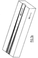
- FIG. 3a models a gas flow F coming from a cooling circuit of a vehicle not equipped with the dilution device according to the invention.
- the exhaust stream is substantially tubular and the core temperature of the stream remains high.
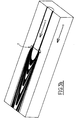
- FIG. 3b models the gas flow coming from the same cooling circuit but provided with the dilution device according to the invention.
- the dilution conditions were modeled to be the most unfavorable (the gas temperature is 160 ° C and the air temperature 30 ° C, the gas flow F and the wind V are oriented in the Same direction).
- the alternation of dark bands and light bands corresponds to gradients of 10 ° C.
- FIG. 3b shows that the invention makes it possible to rapidly reduce the temperature of the flow, both in its periphery and in its center.
- the conical profiled element of FIG. 2 may be replaced by a hemispherical, spiral-conical, hyperbolic, parabolic or semi-elliptical profiled element, or any other type of profile whose shape makes it possible to bend the gas flow towards the blades.
- the number of blades and their inclination will be determined according to the orientation that is desired to give the gas flow.
Landscapes
- Engineering & Computer Science (AREA)
- Chemical & Material Sciences (AREA)
- Combustion & Propulsion (AREA)
- Mechanical Engineering (AREA)
- General Engineering & Computer Science (AREA)
- Exhaust Gas After Treatment (AREA)
- Sampling And Sample Adjustment (AREA)
- Cylinder Crankcases Of Internal Combustion Engines (AREA)
- Exhaust Silencers (AREA)
Description
- Le secteur technique de la présente invention est celui des dispositifs destinés à réduire les signatures visible et infrarouge des véhicules militaires, au niveau de leur gaz d'échappement.
- L'évolution de la technologie des caméras et capteurs thermiques permet de détecter à de très grandes distances des sources chaudes dans l'environnement terrestre, tels des gaz d'échappement et de refroidissement du moteur d'un véhicule. Pour améliorer la furtivité face à l'évolution des capteurs infrarouges, il devient donc nécessaire de réduire le niveau d'énergie rayonnée par les flux d'échappement et de refroidissement des véhicules militaires.
- Il existe déjà des publications proposant un dispositif de dilution uniforme des gaz d'échappement d'un véhicule militaire. C'est le cas du brevet FR-2 776 705 qui décrit un dispositif où l'air est refroidi dans une aire de refroidissement puis rejeté vers l'extérieur par une sortie munie de persiennes. Ces dispositifs présentent cependant un inconvénient majeur. En effet, bien que la température des gaz éjectés soit largement diminuée, ces gaz demeurent repérables en raison de la forme de leur flux de sortie dont la trace est visible sous forme de panache par des équipements à vision infrarouges.
- Une solution pour dissiper rapidement ce panache consiste à appliquer à la sortie du tube d'échappement des gaz du véhicule un disperseur de jet dont les pales dispersent radialement le flux gazeux. Cependant, un inconvénient majeur de ce type de solution demeure dans le fait qu'un tel disperseur de jet constitue un obstacle au flux gazeux et diminue de ce fait les performances du véhicule (en particulier lors des phases d'accélération du véhicule).
- Le brevet US 2 112534 décrit un dispositif d'évacuation des gaz de combustion d'un moteur de locomotive. Ce dispositif comporte notamment une turbine de ventilation, composée d'un moteur électrique et de pales actionnées par le moteur électrique et reliées entre-elles par un moyeu, de forme semi-ovoïdale. La turbine permet de générer une circulation forcée d'air de l'intérieur de l'enceinte vers l'extérieur de cette enceinte.
- Un tel dispositif a pour inconvénient de générer une circulation forcée, ce qui va à l'encontre de l'objectif de l'invention qui vise à résoudre le problème technique de la dissipation et de la dilution rapide des gaz d'échappement. De plus les pales mises en oeuvre dans ce document doivent être d'une forme adéquate à l'entraînement d'air, forme qui engendre obligatoirement des pertes de charges.
- Le but de la présente invention est de fournir un dispositif permettant de dissiper et diluer rapidement les gaz en scindant et en déviant le flot du panache gazeux initial, sans pour autant lui opposer d'obstacle notable, pour l'aider à se dissiper dans l'air environnant.
- L'invention a donc pour objet un dispositif de dilution et de dispersion des gaz d'échappement et/ou de l'air de refroidissement du moteur d'un véhicule, comportant des pales et un moyeu, caractérisé en ce que le moyeu du dispositif comporte un moyen destiné à réduire des pertes de charges du flux gazeux.
- Selon une autre caractéristique de l'invention, le moyen de réduction de pertes de charges est constitué par au moins une ouverture dans le moyeu.
- Selon encore une autre caractéristique, le nombre d'ouvertures, leur diamètre et leur disposition sont déterminés en fonction de la perméabilité que l'on souhaite conférer au dispositif.
- Selon une autre caractéristique, le moyen de réduction de pertes de charges est constitué par un élément profilé permettant d'infléchir le flux gazeux en direction des pales.
- Selon une autre caractéristique, les pales sont fixées sur un anneau.
- Selon une autre caractéristique, l'anneau est libre en rotation par rapport au moyeu.
- Selon une autre caractéristique, l'anneau est solidaire du moyeu.
- Un tout premier avantage du dispositif selon l'invention réside dans sa facilité de montage sur un véhicule, sans nécessiter d'adaptation des éléments équipant déjà le véhicule.
- Un autre avantage réside dans la facilité de mise en oeuvre du dispositif et dans son coût relativement limité.
- Un autre avantage réside dans le fait que ce dispositif influe relativement peu sur les performances du véhicule qu'il équipe.
- D'autres caractéristiques, détails et avantages de l'invention ressortiront plus clairement de la description donnée ci-après à titre indicatif en relation avec des dessins dans lesquels :
- la figure 1a représente en vue de face un premier exemple de réalisation d'un dispositif selon l'invention,
- la figure 1b est une vue de trois-quarts des pales du dispositif selon le même exemple de réalisation,
- la figure 2 représente en vue de trois-quarts un second exemple de réalisation d'un dispositif selon l'invention,
- la figure 3a est une modélisation d'un flux de gaz de refroidissement d'un véhicule non-équipé du dispositif selon l'invention, et
- la figure 3b est une modélisation d'un flux de gaz de refroidissement d'un véhicule équipe du dispositif selon l'invention.
- La figure 1a est une vue de face qui représente un premier exemple de réalisation d'un dispositif de dilution et de dispersion des gaz d'échappement 1, également appelé disperseur de jet, selon l'invention, destiné à être monté à la sortie d'un tube d'échappement (non représenté) des gaz du moteur d'un véhicule, par exemple un véhicule militaire. La figure 1b représente les pales du même disperseur de jet en vue de trois-quarts. Bien entendu, ce dispositif peut être monté sans modification sensible dans le conduit d'évacuation de l'air de refroidissement du moteur ou de tout autre élément chaud du véhicule.
- Le disperseur de jet 1 est composé de pales 2, d'un anneau 3, et d'un moyeu 4. Les pales 2 sont solidaires de l'anneau 3 qui, dans cet exemple de réalisation, est libre en rotation par rapport au moyeu 4. L'inclinaison des pales 2 par rapport à leur axe Z de rotation est comprise entre 20° et 75°. Cet angle est un angle constant, dans le cas de pales planes. Dans le cas de pales vrillées, l'inclinaison varie progressivement au fil du rayon. Ces pales 2 ne couvrent pas la totalité de la circonférence de l'anneau 3, entre ces pales des secteurs libres de tout obstacle permettent une circulation minimale du flux.
- Le moyeu 4 est muni d'ouvertures circulaires 5. Le nombre d'ouvertures et leur diamètre sont déterminés en fonction de la perméabilité que l'on souhaite conférer au dispositif.
- Ce mode de réalisation permet de combiner un flux sensiblement unidirectionnel et un flux dispersé radialement. Le flux unidirectionnel est lié aux ouvertures 5 et le flux dispersé est lié aux pales 2. La dispersion du flux gazeux par les pales est fonction de l'angle de celles-ci. Un angle élevé produit peu de contre-pression dans le conduit d'échappement, mais une dilution relativement limitée, tandis qu'un angle faible induit une excellente dilution mais avec une contre-pression plus marquée, donc plus de pertes de charges. Le nombre d'ouvertures et leur diamètre permettent d'autoriser un flux unidirectionnel plus ou moins important. En effet, s'il n'y a aucune ouverture, le flux unidirectionnel est nul. Les pertes de charges sont alors élevées mais la dilution du flux est meilleure. Par contre, un nombre important d'ouvertures et/ou des ouvertures d'un diamètre important engendrent un flux unidirectionnel important, ce qui diminue les pertes de charges mais atténue la dilution des gaz.
- Le nombre d'ouvertures, leur disposition et leur diamètre seront donc calculés afin d'adapter la dilution des gaz d'échappement en fonction de la furtivité recherchée et du rendement que l'on souhaite obtenir du véhicule.
- La figure 2 est une vue de trois-quarts représentant un second exemple de réalisation d'un disperseur de jet selon l'invention.
- Dans cet exemple de réalisation, le moyeu central 4 ne comporte aucune ouverture mais est muni d'un élément profilé 6 conique destiné à orienter le flux gazeux vers les pales 2. Les pales 2 sont soit fixées sur le moyeu central 4, soit libres en rotation autour de l'axe Z et décrivent un volume V. La base du cône est reliée au moyeu de façon connue, la pointe étant dirigée vers l'amont du flux.
- Dans ce mode de réalisation, on cherche à dévier le flux F des gaz, initialement parallèle à l'axe Z, vers les pales 2 en minimisant les pertes de charges. La forme de l'élément profilé 6 sera donc définie en fonction des caractéristiques du flux, des pales 2 et des résultats recherchés.
- Les figures 3a et 3b représentent des modélisations d'un flux de gaz de refroidissement d'un véhicule. Ces figures illustrent la contribution apportée par l'invention telle que revendiquée à l'état de la technique. La figure 3a modélise un flux gazeux F issu d'un circuit de refroidissement d'un véhicule non muni du dispositif de dilution selon l'invention. Dans ce cas, le flux d'échappement est sensiblement tubulaire et la température centrale du flux reste élevée.
- La figure 3b modélise le flux gazeux issu du même circuit de refroidissement mais muni du dispositif de dilution selon l'invention. Dans ce cas, les conditions de dilutions ont été modélisées pour être les plus défavorables (la température des gaz est de 160 °C et la température de l'air de 30 °C, le flux gazeux F et le vent V sont orientés dans le même sens). L'alternance de bandes sombres et de bandes claires correspond à des gradients de 10 °C. La figure 3b montre que l'invention permet de réduire rapidement la température du flux, aussi bien dans sa périphérie qu'en son centre.
- Ces réalisations de l'invention ont été données à titre d'exemple. D'autres réalisations sont possibles. On pourra notamment remplacer l'élément profilé conique de la figure 2 par un élément profilé hémisphérique, spiralo-conique, hyperbolique, parabolique ou semi-elliptique, ou tout autre type de profil dont la forme permet d'infléchir le flux gazeux en direction des pales.
- Pour tous les modes de réalisations, on déterminera le nombre de pales et leur inclinaison selon l'orientation que l'on souhaite donner au flux gazeux.
Claims (7)
- Dispositif de dilution et de dispersion des gaz d'échappement et/ou de l'air de refroidissement du moteur d'un véhicule, comportant des pales (2) et un moyeu (4), caractérisé en ce que le moyeu (4) comporte un moyen (5, 6) de réduction des pertes de charges du flux gazeux.
- Dispositif de dilution et de dispersion des gaz d'échappement et/ou de l'air de refroidissement selon la revendication 1, caractérisé en ce que le moyen (5) de réduction de pertes de charges est constitué par une ou plusieurs ouvertures (5) dans le moyeu (4).
- Dispositif de dilution et de dispersion des gaz d'échappement et/ou de l'air de refroidissement selon la revendication 2, le nombre d'ouvertures (5), leur diamètre et leur disposition sont déterminés en fonction de la perméabilité que l'on souhaite conférer au dispositif.
- Dispositif de dilution et de dispersion des gaz d'échappement et/ou de l'air de refroidissement selon la revendication 1, caractérisé en ce que le moyen (6) de réduction de pertes de charges est constitué par un élément profilé (6) permettant d'infléchir le flux gazeux en direction des pales (2).
- Dispositif de dilution et de dispersion des gaz d'échappement et/ou de l'air de refroidissement selon l'une quelconque des revendications de l'air prédentes, caractérisé en ce que les pales (2) sont fixées sur un anneau (3).
- Dispositif de dilution et de dispersion des gaz d'échappement et/ou de l'air de refroidissement selon la revendication 5, caractérisé en ce que l'anneau (3) est libre en rotation par rapport au moyeu (4).
- Dispositif de dilution et de dispersion des gaz d'échappement et/ou de l'air de refroidissement selon la revendication 5, caractérisé en ce que l'anneau (3) est solidaire du moyeu (4).
Applications Claiming Priority (2)
| Application Number | Priority Date | Filing Date | Title |
|---|---|---|---|
| FR0303124A FR2852354B1 (fr) | 2003-03-13 | 2003-03-13 | Dispositif de dilution des gaz d'echappement |
| FR0303124 | 2003-03-13 |
Publications (2)
| Publication Number | Publication Date |
|---|---|
| EP1457648A1 EP1457648A1 (fr) | 2004-09-15 |
| EP1457648B1 true EP1457648B1 (fr) | 2006-02-01 |
Family
ID=32749789
Family Applications (1)
| Application Number | Title | Priority Date | Filing Date |
|---|---|---|---|
| EP04290578A Expired - Lifetime EP1457648B1 (fr) | 2003-03-13 | 2004-03-03 | Dispositif de dilution des gaz d'échappement |
Country Status (6)
| Country | Link |
|---|---|
| US (1) | US7690195B2 (fr) |
| EP (1) | EP1457648B1 (fr) |
| AT (1) | ATE317055T1 (fr) |
| DE (1) | DE602004000368T2 (fr) |
| ES (1) | ES2256825T3 (fr) |
| FR (1) | FR2852354B1 (fr) |
Families Citing this family (5)
| Publication number | Priority date | Publication date | Assignee | Title |
|---|---|---|---|---|
| FR2891008B1 (fr) | 2005-09-21 | 2010-06-25 | Giat Ind Sa | Dispositif de discretion infrarouge pour un conduit d'echappement d'un moteur de vehicule |
| JP5027880B2 (ja) * | 2006-09-07 | 2012-09-19 | ボルボ トラックス ノース アメリカ | 業務用トラックの排気ディフューザ |
| FR3030647B1 (fr) | 2014-12-22 | 2019-04-05 | Renault S.A.S | Pompe a huile a debit variable. |
| CA3055395C (fr) | 2018-09-17 | 2025-09-23 | Delta Faucet Company | Dispositif d`entree de distributeur-doseur |
| US20250276294A1 (en) * | 2024-03-04 | 2025-09-04 | Huaneng (Tianjin) Gas Power Co., Ltd. | Quench device and mixing method for improving mixing effect of quench gas and synthesis gas |
Family Cites Families (12)
| Publication number | Priority date | Publication date | Assignee | Title |
|---|---|---|---|---|
| US2112534A (en) * | 1935-04-20 | 1938-03-29 | John S Keen | Locomotive engine exhaust |
| US2518660A (en) * | 1944-09-07 | 1950-08-15 | Wright Aeronautical Corp | Internal-combustion engine and exhaust gas turbine therefor |
| US4352638A (en) * | 1979-11-05 | 1982-10-05 | Ford Motor Company | Rotor assembly for wave compression supercharger |
| US4875829A (en) * | 1988-08-31 | 1989-10-24 | Van Der Woude Plastic Corporation | Marine propeller |
| US4931026A (en) * | 1989-04-24 | 1990-06-05 | Woodland Sylvester L | Jet propeller |
| US4909346A (en) * | 1989-06-27 | 1990-03-20 | Nordam | Jet engine noise suppression system |
| US5941069A (en) * | 1993-10-22 | 1999-08-24 | Madison Combustion Associates | Exhaust apparatus |
| US5542249A (en) * | 1993-10-22 | 1996-08-06 | Madison Combustion Associates | Exhaust apparatus |
| US5709529A (en) * | 1995-11-14 | 1998-01-20 | Westinghouse Electric Corporation | Optimization of turbomachinery harmonics |
| US6158412A (en) * | 1999-09-21 | 2000-12-12 | Kim; Jay S. | Air turbulence generator of internal combustion engines |
| DE10230044A1 (de) * | 2002-07-04 | 2004-02-05 | 3W-Modellmotoren Gmbh | Schalldämpfer |
| US7028663B1 (en) * | 2005-01-26 | 2006-04-18 | Kim Jay S | Fluid swirling device |
-
2003
- 2003-03-13 FR FR0303124A patent/FR2852354B1/fr not_active Expired - Fee Related
-
2004
- 2004-03-03 AT AT04290578T patent/ATE317055T1/de active
- 2004-03-03 DE DE602004000368T patent/DE602004000368T2/de not_active Expired - Lifetime
- 2004-03-03 EP EP04290578A patent/EP1457648B1/fr not_active Expired - Lifetime
- 2004-03-03 ES ES04290578T patent/ES2256825T3/es not_active Expired - Lifetime
- 2004-03-11 US US10/797,014 patent/US7690195B2/en not_active Expired - Fee Related
Also Published As
| Publication number | Publication date |
|---|---|
| FR2852354B1 (fr) | 2006-08-04 |
| DE602004000368D1 (de) | 2006-04-13 |
| US7690195B2 (en) | 2010-04-06 |
| EP1457648A1 (fr) | 2004-09-15 |
| ES2256825T3 (es) | 2006-07-16 |
| DE602004000368T2 (de) | 2006-08-03 |
| US20050005594A1 (en) | 2005-01-13 |
| ATE317055T1 (de) | 2006-02-15 |
| FR2852354A1 (fr) | 2004-09-17 |
Similar Documents
| Publication | Publication Date | Title |
|---|---|---|
| EP2281108B1 (fr) | Dispositif de prélèvement d'air d'un compresseur d'une turbomachine | |
| EP1881179B1 (fr) | Système de ventilation de paroi de chambre de combustion dans une turbomachine | |
| EP3007977B1 (fr) | Ensemble de propulsion électrique pour aéronef | |
| EP1881182B2 (fr) | Système de refroidissement d'une cavité aval de rouet de compresseur centrifuge | |
| EP2657531A1 (fr) | Ventilateur axial avec redresseur à effet centripète ayant un moyeux de diamètre réduit | |
| EP2279341B1 (fr) | Dispositif de réduction du bruit généré par un réacteur d'aéronef à conduits de fluide coudés | |
| EP1138954A1 (fr) | Ventilateur centrifuge | |
| WO2020188191A1 (fr) | Module de refroidissement pour véhicule automobile électrique à turbomachine tangentielle | |
| WO2019092358A1 (fr) | Systeme de mise en mouvement d'air | |
| FR2852354A1 (fr) | Dispositif de dilution des gaz d'echappement | |
| EP2839165B1 (fr) | Ventilateur pour automobile a encombrement axial reduit | |
| FR2622637A1 (fr) | Buse d'echappement pour un dispositif de propulsion a helice propulsive | |
| EP4077012A1 (fr) | Module de dispositif de ventilation pour module de refroidissement de véhicule automobile, dispositif de ventilation comportant un tel module et module de refroidissement pour véhicule automobile comprenant un tel dispositif de ventilation | |
| FR2793530A1 (fr) | Assemblage de moteur a grand volume, basse pression | |
| WO2014114859A1 (fr) | Appareil d'assistance respiratoire avec turbine insonorisée | |
| FR3093763A1 (fr) | Module de refroidissement à zone sacrificielle pour véhicule automobile électrique | |
| EP2975270A1 (fr) | Dispositif de ventilation à encombrement axial réduit | |
| FR2784274A1 (fr) | Appareil seche-cheveux | |
| EP3938632A1 (fr) | Module de refroidissement pour véhicule automobile électrique à turbomachine tangentielle | |
| WO2026062342A1 (fr) | Machine electrique comprenant un dispositif de ventilation | |
| FR2564531A1 (fr) | Ventilateur centrifuge | |
| FR3166488A1 (fr) | Machine électrique comprenant des ailettes inclinables | |
| WO2013156257A1 (fr) | Ventilateur pour automobile comportant un stator en amont de l'helice | |
| FR3151353A1 (fr) | Bec de separation d’un flux pour une turbomachine d’aeronef | |
| FR3093764A1 (fr) | Module de refroidissement pour véhicule automobile électrique à turbomachine tangentielle |
Legal Events
| Date | Code | Title | Description |
|---|---|---|---|
| PUAI | Public reference made under article 153(3) epc to a published international application that has entered the european phase |
Free format text: ORIGINAL CODE: 0009012 |
|
| AK | Designated contracting states |
Kind code of ref document: A1 Designated state(s): AT BE BG CH CY CZ DE DK EE ES FI FR GB GR HU IE IT LI LU MC NL PL PT RO SE SI SK TR |
|
| AX | Request for extension of the european patent |
Extension state: AL HR LT LV MK |
|
| RIN1 | Information on inventor provided before grant (corrected) |
Inventor name: PIZON, BENOIT Inventor name: CARLIER, SYLVAIN Inventor name: BRUN, MICHEL |
|
| 17P | Request for examination filed |
Effective date: 20050118 |
|
| 17Q | First examination report despatched |
Effective date: 20050221 |
|
| AKX | Designation fees paid |
Designated state(s): AT BE BG CH CY CZ DE DK EE ES FI FR GB GR HU IE IT LI LU MC NL PL PT RO SE SI SK TR |
|
| GRAP | Despatch of communication of intention to grant a patent |
Free format text: ORIGINAL CODE: EPIDOSNIGR1 |
|
| GRAS | Grant fee paid |
Free format text: ORIGINAL CODE: EPIDOSNIGR3 |
|
| GRAA | (expected) grant |
Free format text: ORIGINAL CODE: 0009210 |
|
| AK | Designated contracting states |
Kind code of ref document: B1 Designated state(s): AT BE BG CH CY CZ DE DK EE ES FI FR GB GR HU IE IT LI LU MC NL PL PT RO SE SI SK TR |
|
| PG25 | Lapsed in a contracting state [announced via postgrant information from national office to epo] |
Ref country code: IE Free format text: LAPSE BECAUSE OF FAILURE TO SUBMIT A TRANSLATION OF THE DESCRIPTION OR TO PAY THE FEE WITHIN THE PRESCRIBED TIME-LIMIT Effective date: 20060201 Ref country code: NL Free format text: LAPSE BECAUSE OF FAILURE TO SUBMIT A TRANSLATION OF THE DESCRIPTION OR TO PAY THE FEE WITHIN THE PRESCRIBED TIME-LIMIT Effective date: 20060201 Ref country code: RO Free format text: LAPSE BECAUSE OF FAILURE TO SUBMIT A TRANSLATION OF THE DESCRIPTION OR TO PAY THE FEE WITHIN THE PRESCRIBED TIME-LIMIT Effective date: 20060201 Ref country code: SK Free format text: LAPSE BECAUSE OF FAILURE TO SUBMIT A TRANSLATION OF THE DESCRIPTION OR TO PAY THE FEE WITHIN THE PRESCRIBED TIME-LIMIT Effective date: 20060201 Ref country code: SI Free format text: LAPSE BECAUSE OF FAILURE TO SUBMIT A TRANSLATION OF THE DESCRIPTION OR TO PAY THE FEE WITHIN THE PRESCRIBED TIME-LIMIT Effective date: 20060201 Ref country code: PL Free format text: LAPSE BECAUSE OF FAILURE TO SUBMIT A TRANSLATION OF THE DESCRIPTION OR TO PAY THE FEE WITHIN THE PRESCRIBED TIME-LIMIT Effective date: 20060201 |
|
| REG | Reference to a national code |
Ref country code: GB Ref legal event code: FG4D Free format text: NOT ENGLISH |
|
| REG | Reference to a national code |
Ref country code: CH Ref legal event code: NV Representative=s name: ING. MARCO ZARDI C/O M. ZARDI & CO. S.A. Ref country code: CH Ref legal event code: EP |
|
| GBT | Gb: translation of ep patent filed (gb section 77(6)(a)/1977) |
Effective date: 20060201 |
|
| REG | Reference to a national code |
Ref country code: IE Ref legal event code: FG4D Free format text: LANGUAGE OF EP DOCUMENT: FRENCH |
|
| PG25 | Lapsed in a contracting state [announced via postgrant information from national office to epo] |
Ref country code: BE Free format text: LAPSE BECAUSE OF NON-PAYMENT OF DUE FEES Effective date: 20060331 Ref country code: MC Free format text: LAPSE BECAUSE OF NON-PAYMENT OF DUE FEES Effective date: 20060331 |
|
| REF | Corresponds to: |
Ref document number: 602004000368 Country of ref document: DE Date of ref document: 20060413 Kind code of ref document: P |
|
| PG25 | Lapsed in a contracting state [announced via postgrant information from national office to epo] |
Ref country code: BG Free format text: LAPSE BECAUSE OF FAILURE TO SUBMIT A TRANSLATION OF THE DESCRIPTION OR TO PAY THE FEE WITHIN THE PRESCRIBED TIME-LIMIT Effective date: 20060501 Ref country code: DK Free format text: LAPSE BECAUSE OF FAILURE TO SUBMIT A TRANSLATION OF THE DESCRIPTION OR TO PAY THE FEE WITHIN THE PRESCRIBED TIME-LIMIT Effective date: 20060501 |
|
| REG | Reference to a national code |
Ref country code: SE Ref legal event code: TRGR |
|
| NLV1 | Nl: lapsed or annulled due to failure to fulfill the requirements of art. 29p and 29m of the patents act | ||
| PG25 | Lapsed in a contracting state [announced via postgrant information from national office to epo] |
Ref country code: PT Free format text: LAPSE BECAUSE OF FAILURE TO SUBMIT A TRANSLATION OF THE DESCRIPTION OR TO PAY THE FEE WITHIN THE PRESCRIBED TIME-LIMIT Effective date: 20060703 |
|
| REG | Reference to a national code |
Ref country code: ES Ref legal event code: FG2A Ref document number: 2256825 Country of ref document: ES Kind code of ref document: T3 |
|
| REG | Reference to a national code |
Ref country code: IE Ref legal event code: FD4D |
|
| PLBE | No opposition filed within time limit |
Free format text: ORIGINAL CODE: 0009261 |
|
| STAA | Information on the status of an ep patent application or granted ep patent |
Free format text: STATUS: NO OPPOSITION FILED WITHIN TIME LIMIT |
|
| 26N | No opposition filed |
Effective date: 20061103 |
|
| BERE | Be: lapsed |
Owner name: GIAT INDUSTRIES Effective date: 20060331 |
|
| PG25 | Lapsed in a contracting state [announced via postgrant information from national office to epo] |
Ref country code: CZ Free format text: LAPSE BECAUSE OF FAILURE TO SUBMIT A TRANSLATION OF THE DESCRIPTION OR TO PAY THE FEE WITHIN THE PRESCRIBED TIME-LIMIT Effective date: 20060201 Ref country code: GR Free format text: LAPSE BECAUSE OF FAILURE TO SUBMIT A TRANSLATION OF THE DESCRIPTION OR TO PAY THE FEE WITHIN THE PRESCRIBED TIME-LIMIT Effective date: 20060502 |
|
| PG25 | Lapsed in a contracting state [announced via postgrant information from national office to epo] |
Ref country code: EE Free format text: LAPSE BECAUSE OF FAILURE TO SUBMIT A TRANSLATION OF THE DESCRIPTION OR TO PAY THE FEE WITHIN THE PRESCRIBED TIME-LIMIT Effective date: 20060201 |
|
| PG25 | Lapsed in a contracting state [announced via postgrant information from national office to epo] |
Ref country code: LU Free format text: LAPSE BECAUSE OF NON-PAYMENT OF DUE FEES Effective date: 20060303 Ref country code: HU Free format text: LAPSE BECAUSE OF FAILURE TO SUBMIT A TRANSLATION OF THE DESCRIPTION OR TO PAY THE FEE WITHIN THE PRESCRIBED TIME-LIMIT Effective date: 20060802 |
|
| PG25 | Lapsed in a contracting state [announced via postgrant information from national office to epo] |
Ref country code: CY Free format text: LAPSE BECAUSE OF FAILURE TO SUBMIT A TRANSLATION OF THE DESCRIPTION OR TO PAY THE FEE WITHIN THE PRESCRIBED TIME-LIMIT Effective date: 20060201 |
|
| REG | Reference to a national code |
Ref country code: CH Ref legal event code: PUE Owner name: NEXTER SYSTEMS Free format text: GIAT INDUSTRIES#13, ROUTE DE LA MINIERE#78000 VERSAILLES (FR) -TRANSFER TO- NEXTER SYSTEMS#34, BOULEVARD DE VALMY#42300 ROANNE (FR) |
|
| REG | Reference to a national code |
Ref country code: GB Ref legal event code: 732E Free format text: REGISTERED BETWEEN 20090625 AND 20090701 |
|
| REG | Reference to a national code |
Ref country code: CH Ref legal event code: NV Representative=s name: ING. MARCO ZARDI C/O M. ZARDI & CO. S.A. |
|
| PGFP | Annual fee paid to national office [announced via postgrant information from national office to epo] |
Ref country code: TR Payment date: 20120228 Year of fee payment: 9 |
|
| PGFP | Annual fee paid to national office [announced via postgrant information from national office to epo] |
Ref country code: IT Payment date: 20120223 Year of fee payment: 9 |
|
| PGFP | Annual fee paid to national office [announced via postgrant information from national office to epo] |
Ref country code: ES Payment date: 20130305 Year of fee payment: 10 Ref country code: SE Payment date: 20130226 Year of fee payment: 10 Ref country code: CH Payment date: 20130226 Year of fee payment: 10 Ref country code: FI Payment date: 20130222 Year of fee payment: 10 Ref country code: GB Payment date: 20130228 Year of fee payment: 10 Ref country code: DE Payment date: 20130221 Year of fee payment: 10 |
|
| PGFP | Annual fee paid to national office [announced via postgrant information from national office to epo] |
Ref country code: AT Payment date: 20130225 Year of fee payment: 10 |
|
| PGFP | Annual fee paid to national office [announced via postgrant information from national office to epo] |
Ref country code: FR Payment date: 20130429 Year of fee payment: 10 |
|
| REG | Reference to a national code |
Ref country code: DE Ref legal event code: R119 Ref document number: 602004000368 Country of ref document: DE |
|
| PG25 | Lapsed in a contracting state [announced via postgrant information from national office to epo] |
Ref country code: FI Free format text: LAPSE BECAUSE OF NON-PAYMENT OF DUE FEES Effective date: 20140303 |
|
| REG | Reference to a national code |
Ref country code: CH Ref legal event code: PL |
|
| REG | Reference to a national code |
Ref country code: SE Ref legal event code: EUG |
|
| REG | Reference to a national code |
Ref country code: AT Ref legal event code: MM01 Ref document number: 317055 Country of ref document: AT Kind code of ref document: T Effective date: 20140303 |
|
| REG | Reference to a national code |
Ref country code: DE Ref legal event code: R079 Ref document number: 602004000368 Country of ref document: DE Free format text: PREVIOUS MAIN CLASS: F01N0007080000 Ipc: F01N0013080000 |
|
| GBPC | Gb: european patent ceased through non-payment of renewal fee |
Effective date: 20140303 |
|
| PG25 | Lapsed in a contracting state [announced via postgrant information from national office to epo] |
Ref country code: SE Free format text: LAPSE BECAUSE OF NON-PAYMENT OF DUE FEES Effective date: 20140304 |
|
| REG | Reference to a national code |
Ref country code: DE Ref legal event code: R079 Ref document number: 602004000368 Country of ref document: DE Free format text: PREVIOUS MAIN CLASS: F01N0007080000 Ipc: F01N0013080000 Effective date: 20141118 Ref country code: DE Ref legal event code: R119 Ref document number: 602004000368 Country of ref document: DE Effective date: 20141001 |
|
| REG | Reference to a national code |
Ref country code: FR Ref legal event code: ST Effective date: 20141128 |
|
| PG25 | Lapsed in a contracting state [announced via postgrant information from national office to epo] |
Ref country code: GB Free format text: LAPSE BECAUSE OF NON-PAYMENT OF DUE FEES Effective date: 20140303 Ref country code: DE Free format text: LAPSE BECAUSE OF NON-PAYMENT OF DUE FEES Effective date: 20141001 Ref country code: LI Free format text: LAPSE BECAUSE OF NON-PAYMENT OF DUE FEES Effective date: 20140331 Ref country code: CH Free format text: LAPSE BECAUSE OF NON-PAYMENT OF DUE FEES Effective date: 20140331 Ref country code: FR Free format text: LAPSE BECAUSE OF NON-PAYMENT OF DUE FEES Effective date: 20140331 |
|
| PG25 | Lapsed in a contracting state [announced via postgrant information from national office to epo] |
Ref country code: AT Free format text: LAPSE BECAUSE OF NON-PAYMENT OF DUE FEES Effective date: 20140303 |
|
| PG25 | Lapsed in a contracting state [announced via postgrant information from national office to epo] |
Ref country code: IT Free format text: LAPSE BECAUSE OF NON-PAYMENT OF DUE FEES Effective date: 20140303 |
|
| PG25 | Lapsed in a contracting state [announced via postgrant information from national office to epo] |
Ref country code: ES Free format text: LAPSE BECAUSE OF NON-PAYMENT OF DUE FEES Effective date: 20140304 |
|
| PG25 | Lapsed in a contracting state [announced via postgrant information from national office to epo] |
Ref country code: TR Free format text: LAPSE BECAUSE OF NON-PAYMENT OF DUE FEES Effective date: 20140303 |