EP1456728B1 - Einrichtung mit steuerbarer impedanz - Google Patents
Einrichtung mit steuerbarer impedanz Download PDFInfo
- Publication number
- EP1456728B1 EP1456728B1 EP02803574A EP02803574A EP1456728B1 EP 1456728 B1 EP1456728 B1 EP 1456728B1 EP 02803574 A EP02803574 A EP 02803574A EP 02803574 A EP02803574 A EP 02803574A EP 1456728 B1 EP1456728 B1 EP 1456728B1
- Authority
- EP
- European Patent Office
- Prior art keywords
- control
- winding
- circuit component
- processing unit
- impedance
- Prior art date
- Legal status (The legal status is an assumption and is not a legal conclusion. Google has not performed a legal analysis and makes no representation as to the accuracy of the status listed.)
- Expired - Lifetime
Links
- 238000004804 winding Methods 0.000 claims abstract description 60
- 239000000463 material Substances 0.000 claims abstract description 7
- 230000033228 biological regulation Effects 0.000 claims description 28
- 238000012545 processing Methods 0.000 claims description 22
- 230000005540 biological transmission Effects 0.000 claims description 18
- 239000003990 capacitor Substances 0.000 claims description 16
- 230000008859 change Effects 0.000 claims description 9
- 238000005259 measurement Methods 0.000 claims description 6
- 230000035699 permeability Effects 0.000 claims description 3
- 230000001105 regulatory effect Effects 0.000 abstract description 7
- 230000001276 controlling effect Effects 0.000 abstract description 6
- 230000000052 comparative effect Effects 0.000 description 20
- 230000001965 increasing effect Effects 0.000 description 14
- 230000006870 function Effects 0.000 description 10
- 230000008901 benefit Effects 0.000 description 7
- 230000004907 flux Effects 0.000 description 5
- XEEYBQQBJWHFJM-UHFFFAOYSA-N Iron Chemical compound [Fe] XEEYBQQBJWHFJM-UHFFFAOYSA-N 0.000 description 4
- 230000001939 inductive effect Effects 0.000 description 3
- 238000013016 damping Methods 0.000 description 2
- 230000001419 dependent effect Effects 0.000 description 2
- 239000000696 magnetic material Substances 0.000 description 2
- 238000012423 maintenance Methods 0.000 description 2
- 230000009467 reduction Effects 0.000 description 2
- 230000006641 stabilisation Effects 0.000 description 2
- 230000003068 static effect Effects 0.000 description 2
- 239000004020 conductor Substances 0.000 description 1
- 238000012937 correction Methods 0.000 description 1
- 238000011161 development Methods 0.000 description 1
- 238000010586 diagram Methods 0.000 description 1
- 230000005611 electricity Effects 0.000 description 1
- 230000005284 excitation Effects 0.000 description 1
- 238000001914 filtration Methods 0.000 description 1
- 230000006872 improvement Effects 0.000 description 1
- 229910052742 iron Inorganic materials 0.000 description 1
- 238000003475 lamination Methods 0.000 description 1
- 230000003137 locomotive effect Effects 0.000 description 1
- 230000005415 magnetization Effects 0.000 description 1
- 229910044991 metal oxide Inorganic materials 0.000 description 1
- 150000004706 metal oxides Chemical class 0.000 description 1
- 230000008450 motivation Effects 0.000 description 1
- 230000007935 neutral effect Effects 0.000 description 1
- 230000010363 phase shift Effects 0.000 description 1
- 230000003019 stabilising effect Effects 0.000 description 1
- 239000013589 supplement Substances 0.000 description 1
- 230000001360 synchronised effect Effects 0.000 description 1
- 238000012546 transfer Methods 0.000 description 1
- 230000009466 transformation Effects 0.000 description 1
- 229910000859 α-Fe Inorganic materials 0.000 description 1
Images


Classifications
-
- G—PHYSICS
- G05—CONTROLLING; REGULATING
- G05F—SYSTEMS FOR REGULATING ELECTRIC OR MAGNETIC VARIABLES
- G05F1/00—Automatic systems in which deviations of an electric quantity from one or more predetermined values are detected at the output of the system and fed back to a device within the system to restore the detected quantity to its predetermined value or values, i.e. retroactive systems
- G05F1/10—Regulating voltage or current
- G05F1/12—Regulating voltage or current wherein the variable actually regulated by the final control device is AC
- G05F1/32—Regulating voltage or current wherein the variable actually regulated by the final control device is AC using magnetic devices having a controllable degree of saturation as final control devices
-
- H—ELECTRICITY
- H01—ELECTRIC ELEMENTS
- H01F—MAGNETS; INDUCTANCES; TRANSFORMERS; SELECTION OF MATERIALS FOR THEIR MAGNETIC PROPERTIES
- H01F29/00—Variable transformers or inductances not covered by group H01F21/00
- H01F29/14—Variable transformers or inductances not covered by group H01F21/00 with variable magnetic bias
-
- H—ELECTRICITY
- H02—GENERATION; CONVERSION OR DISTRIBUTION OF ELECTRIC POWER
- H02H—EMERGENCY PROTECTIVE CIRCUIT ARRANGEMENTS
- H02H9/00—Emergency protective circuit arrangements for limiting excess current or voltage without disconnection
- H02H9/08—Limitation or suppression of earth fault currents, e.g. Petersen coil
-
- H—ELECTRICITY
- H02—GENERATION; CONVERSION OR DISTRIBUTION OF ELECTRIC POWER
- H02H—EMERGENCY PROTECTIVE CIRCUIT ARRANGEMENTS
- H02H9/00—Emergency protective circuit arrangements for limiting excess current or voltage without disconnection
- H02H9/02—Emergency protective circuit arrangements for limiting excess current or voltage without disconnection responsive to excess current
- H02H9/021—Current limitation using saturable reactors
-
- H—ELECTRICITY
- H02—GENERATION; CONVERSION OR DISTRIBUTION OF ELECTRIC POWER
- H02J—CIRCUIT ARRANGEMENTS OR SYSTEMS FOR SUPPLYING OR DISTRIBUTING ELECTRIC POWER; SYSTEMS FOR STORING ELECTRIC ENERGY
- H02J3/00—Circuit arrangements for AC mains or AC distribution networks
- H02J3/18—Arrangements for adjusting, eliminating or compensating reactive power in networks
-
- Y—GENERAL TAGGING OF NEW TECHNOLOGICAL DEVELOPMENTS; GENERAL TAGGING OF CROSS-SECTIONAL TECHNOLOGIES SPANNING OVER SEVERAL SECTIONS OF THE IPC; TECHNICAL SUBJECTS COVERED BY FORMER USPC CROSS-REFERENCE ART COLLECTIONS [XRACs] AND DIGESTS
- Y02—TECHNOLOGIES OR APPLICATIONS FOR MITIGATION OR ADAPTATION AGAINST CLIMATE CHANGE
- Y02E—REDUCTION OF GREENHOUSE GAS [GHG] EMISSIONS, RELATED TO ENERGY GENERATION, TRANSMISSION OR DISTRIBUTION
- Y02E40/00—Technologies for an efficient electrical power generation, transmission or distribution
- Y02E40/30—Reactive power compensation
Definitions
- the invention relates to a circuit component with a controllable impedance of the type described in International patent application publication number WO O1/90835.
- a circuit component comprising a body of magnetisable material, a main winding that is wound round the body about a first axis and a control winding that is wound round the body about a second axis.
- US patent publication US 3 757 201 discloses an electric power controlling or regulating system comprising a transformer main magnet core portion which forms a first loop opening, a magnetic control core portion forming a second loop opening, a magnetically contracting and merging with said main core.
- the second opening is outside of and separate from the main core opening.
- Main primary and secondary windings are disposed on the main core portion and pass through the first opening.
- Control windings are disposed on the control core portion and pass through the second opening while staying free of the first opening.
- the magnetic flux interlinking the primary and secondary windings on the main core portion is controllable by varying the excitation of the control windings.
- the second core portion extends either in a plane normal to that of the first loop opening or it extends about the main core portion in the same plane as the latter and has larger dimensions so that the two loop openings are substantially in the same plane.
- International patent application number WO 94/11891 discloses an inductor with variable inductance based on the principle of orthogonal magnetization, that is, control of the permeability of the magnetic material with the aid of a cross-directional control field.
- the inductor has a main winding which is intended for alternating current and which surrounds a tubular core wound from tape-formed magnetic material.
- the core is composed of a plurality of ring cores which hare stacked coaxially one above the other and which are axially divided and angularly displaced relative to each other. Axially through the core extends a control winding intended for direct current.
- the permeability of the core is changed in its axial direction and hence also the inductance of the inductor.
- the eddy-current losses in the core can be considerably reduced by making the core conically tapering towards it ends or by arranging so-called flux funnels with radically bladed laminations near the ends of the core.
- the inductor is especially suitable for use in power plants, for example in tunable harmonic filters for high-voltage direct current.
- WO 97/34210 discloses a device for performing, individually or in combination with each other, the functions of voltage control, power factor correction, current limiting and harmonic filtering at a network, with a line voltage U 0 and a load voltage U, with the aid of a control voltage ⁇ U.
- the device comprises a controllable reactor comprising at least one control winding and at least one power winding for generating the control voltage ⁇ U, as well as a control unit which, via at least one power amplifier, delivers a control current Is to the control winding.
- the power winding is connected in series with the load and through it flows a load current I 0 .
- a measuring member senses the magnetic flux of the controllable reactor and delivers a flux voltage V ⁇ proportional thereto.
- those signals which correspond to the line voltage U 0 , the load voltage U, the control voltage ⁇ U, the load current I 0 and the flux voltage V ⁇ are fed back to the control unit which, in dependence thereon, via the power amplifier(s), delivers such a control current I s to the control winding that the control voltage ⁇ U induced in the power winding supplements the line voltage U 0 such that the relevant functions or function are/is achieved.
- the invention relates to a system for controlling the impedance of a transmission line according to claim 1.
- Optional features of the invention are defined in the dependent claims.
- a major advantage of the invention is that it does not require movable parts or complicated circuits for controlling the impedance value.
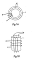
- FIG. 1 The principle behind the invention is illustrated in figure 1.
- a body 1 of a magnetisable material which may be ferrite or iron or other suitable magnetisable materials.
- A1 is wound in a first direction, which in the case illustrated in figure 1A coincides with the body's 1 circumference.
- a second winding, the control winding A2 is also wound around the body 1, but the winding axis is at right angles (perpendicular) to the winding axis for A1, thereby largely avoiding transformative connection between A1 and A2, with the only connection taking place within the magnetisable material.
- connection will be manifested as a change in the material's ⁇ r .
- Rm 1/ ⁇ r ⁇ 0 A
- L N 2 /Rm
- X L jwL
- This characteristic of the invention is particularly useful with regard to regulation, which at the present time is carried out by means of power electronics.
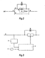
- a comparative example of an implementation of the circuit component disclosed herein is for series compensation in transmission lines (figure 2).
- Series compensation is employed in the case of a power line 12 where connection of various equipment causes the line's total impedance to have an excessively high inductive factor.
- capacitors C1 are inserted.
- the component L1 will then be connected in series to the line 12 where the compensation is to be performed (i.e. the main winding A1 in the component L1 is connected in series to the line 12).
- the component L1 will be connected in parallel to a capacitor or a capacitor battery C1.
- control winding A2 in L1 it will be possible to control the component's L1 impedance from a very low value (where the current in the line 12 passes through the component L1 and not through the capacitor C1) to a high value (where the current in the line 12 largely passes through the capacitor C 1).
- a second application of series compensation is in order to change the impedance value for a transmission line and thereby control power flow between several parallel lines.
- the component L1 it will be possible by means of the component L1 to control the impedance in the line 12 and thereby the load distribution between the lines 12 and 13. According to the prior art it is possible by this means to perform load flow regulation (current limiting or redistribution of power flow) and stability control.
- a series compensation of this kind is carried out by means of a thyristor-controlled or thyristor-connected series capacitor (CSCS, TSSC).
- CSCS thyristor-controlled or thyristor-connected series capacitor
- TSSC thyristor-connected series capacitor
- An embodiment of the invention comprises a measuring unit 2 for measuring parameters concerning the line's operation (U, I cos ⁇ , P, Q, S, f), a processing unit with inputs and outputs where a first input is connected to the measuring unit so that the results of the measurement are transmitted to the processing unit, a second input is connected to an input unit for input of desired values, and at least one output, where the output signal is converted to a current control signal with a desired frequency (this current may be direct current or alternating current) and intensity, and a circuit component with controllable impedance comprising a main winding for connecting to the transmission line and a control winding for connecting to the processing unit, with the result that the processing unit controls the component's impedance on the basis of the ratio between the measurement results and the desired values.
- a measuring unit 2 for measuring parameters concerning the line's operation (U, I cos ⁇ , P, Q, S, f)
- a processing unit with inputs and outputs where a first input is connected to the measuring unit so that
- FIG. 3 A simplified block diagram of an embodiment of the invention is illustrated in figure 3.
- the system comprises a measuring unit 2 for connecting to a transmission line 12, which has to be series compensated, and which will measure the line's operating parameters, such as voltage, current, cos ⁇ .
- the measured values are transmitted to a processing unit 4, which in an embodiment of the invention is also fed with desired values.
- the processing unit Based on the input values the processing unit computes a desired value for the impedance of the component L1 and thereby the necessary control current value that will be applied to the control winding A2 in the component.
- the embodiment constitutes a controllable series reactor that may be employed in combination with a series battery.
- the invention has great utilitarian value since it will lead to increased network utilisation (increased load limits) as a result of the ability to regulate power flow (in normal operation or after a fault), or as a result of increased stability limits.
- the maximum output may preferably be of the order of 3000 A, with an impedance of 10-50 ohm.
- the regulating system (which in the described example is provided in the processing unit 4) should be able to follow power changes with a frequency of up to 10 Hz if the unit is to be used for stability control. If it is to be used for compensation of subsynchronous resonance it will have to be raised to 30-50 Hz.
- a comparative example of an implementation of the circuit component disclosed herein is as a shunt compensator in transmission lines, i.e. as a controllable shunt reactor possibly in combination with a shunt battery.
- this kind of shunt compensation is performed by means of thyristor-controlled reactors (TCR), with all the drawbacks this entails.
- TCR thyristor-controlled reactors
- the shunt compensation is implemented by means of a circuit component L1 with a main winding A1, which is connected on one side to a transmission line 13 and on the other side is connected to a capacitor C1.
- the capacitor C1 in turn is connected to earth.
- the compensation is carried out by changing the impedance of the circuit component L1 by means of the control winding A2 and thereby changing the total impedance of the series L1-C1.
- the total impedance for the series connection will therefore vary from purely inductive (high value of impedance for the component L1) to zero (series resonance between L1 and C1) and thereafter to purely capacitive (low value of impedance for the circuit component L1).
- the system comprises a system for shunt compensation, with a measuring unit, a processing unit and a controllable circuit component, where the main winding A1 is arranged for connection in parallel with the transmission line 13, and where the system further comprises a capacitor or a capacitor battery C1 connected in series with the circuit component's L1 main winding A1 for shunt compensation of the transmission line 13.
- the function of this embodiment of the invention will be reactive compensation and voltage regulation in the transmission line.
- output for the shunt reactor this will be of the order of 80-150MV Ar (300kV, 420kV).
- the requirements for regulation of the processing unit will be similar to those for an SVC unit (band width 10-20 Hz).
- MOA metal-oxide-semiconductor
- a comparative example of an implementation of the circuit component disclosed herein is for earth fault compensation.
- the prior art in this field comprises the use of a so-called Petersen coil for limiting earth fault current.
- a Petersen coil is a reactor with an iron core and air gap, which is connected between the network's neutral point and earth.
- Petersen coils are extremely expensive, in addition to which they have to be adjusted mechanically.
- the Petersen coil has to be regulated at all times to resonate with the rest of the system to which it is connected. Impedance changes in the system will therefore lead to the need for a new, mechanical adjustment of the coil. This is cumbersome and expensive, and substantially limits the use of such a coil.
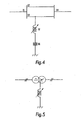
- This comparative example is illustrated schematically in figures 5 and 6.
- Figure 5 illustrates a three-phase converter where the primary windings are connected in delta configuration while the secondary windings are connected in radial configuration.
- the circuit component L1 disclosed herein is therefore arranged between the radial configuration's zero point and earth. By changing the impedance of the circuit component L1 it will be possible to control the earth fault back or return current.
- FIG. 1 Another comparative example of an implementation of the circuit component disclosed herein is in a system for earth fault compensation i.e. for regulating earth fault impedance
- a system for earth fault compensation i.e. for regulating earth fault impedance
- a measuring unit 2 for measuring earth fault back or return current together with other parameters for an electrical component T1
- a processing unit 4 with at least one input and one output, where the input is connected to the measuring unit 2, and in which processing unit the measurement values are compared with desired values for earth fault back current values in order to derive an output signal constituting a control current signal
- this will preferably be up to 200 A.
- This comparative example system has no special protection requirements, and the losses will not be important since the voltage across the circuit component will normally be low.
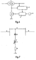
- a further comparative example of an implementation of the circuit component disclosed herein is as a filter, for example as shunt or series compensation with very rapid regulation.
- This rapid regulation will be achieved by simply providing a rapid change in the control current.
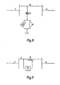
- the above comparative example filter comprises a filter (figure 7 for band-pass filter, figure 8 for high-pass filter) comprising a shunt or series compensator with a main winding for connecting to the main circuit and a control winding for connecting to a control unit.
- a filter figure 7 for band-pass filter, figure 8 for high-pass filter
- the circuit component included in the filter will be able to change the filter's characteristics as required simply by changing the characteristics of the control current.
- FIG. 1 Another comparative example implementing the circuit component disclosed herein is in a filter system, which comprises a filter with the circuit component, together with a measuring and a processing unit for controlling the component's inductance.
- the system's function will be compensation in order to reduce harmonic, phase asymmetry and flicker in addition to reactive compensation.
- FIG. 9 Another comparative example implementing the circuit component disclosed herein is as a current limiter "generator switch”, such as for example a controlled series reactor for current limiting in connection with an electrical load device.
- This example is illustrated in figure 9, and is similar on the whole to that illustrated in figure 3, except that the control will be exclusively conducted on the basis of desired current values.
- the example will also comprise a current limiting system, where it will be possible to provide a switch by means of the circuit component. The switch will then be able to move from an open state (i.e. very high impedance) to a closed state (i.e. - impedance equal to zero) steplessly by means of the control current.
- an open state i.e. very high impedance
- a closed state i.e. - impedance equal to zero
- the function of the system will be current limiting by introducing higher or lower impedance depending on the requirement.
- the invention will represent an alternative to an Is limiter.
- the converter sets in Norway consist mainly of mechanically connected synchronous motor-synchronous generator sets that supply the traction power network with single-phase alternating voltage of approximately 15 kV and frequency equal to 16 2/3 Hz. Stability problems Associated with the converter sets are experienced more and more frequently as a result of the fact that the locomotives are becoming more powerful and more rapidly regulating.
- the problem is due to an inherently poor damping in the converter sets resulting in power fluctuations on the three-phase side (the network side) and thereby a reduction in the quality of electricity. In addition the fluctuations cause increased mechanical wear on the actual sets.
- a comparative example controlled series reactor in connection with the transformer that supplies the converter sets from the network side may be a very effective measure for stabilising its operation.
- the control system must be flexible and configurable, thus enabling the unit to be used for different purposes, such as reactive compensation, active voltage regulation and voltage quality improvement or damping of power fluctuations.
- a transformer device i.e. a circuit component where there are two main windings and one, or possible two control windings, thus permitting the transformer's transformation ratio to be changed by means of one or more control current(s).
- FIG. 9 illustrates two three-phase transformers comprising adjustable circuit components.
- Figure 11 illustrates the principle behind this device.
- Around the magnetisable body 1 is an additional main winding A3 connected in such a manner that the windings A1 and A3 together with the connected body 1 form a transformer.
- the control winding A2 is still present and will regulate the transmission ratio of the transformer. It is also possible to wind the main windings A3 around the same axis as the control winding.
- the output for a circuit component as implemented above will be 200-2000 A. With regard to regulation requirements, there will be no need for rapid regulation, but a regulation of the order of 10 seconds to 1 minute will suffice.
- a major advantage of such transformer devices is that it will lead to much lower maintenance cost compared with today's tap changers.
- the comparative example transformer device can also be employed in connection with a phase angle regulator, which will thereby comprise a transformer component. By regulating the control current it will be possible to control the phase shift between the primary and the secondary side.
- a phase angle regulator of this type is illustrated in figure 12.
- an adjustable series transformer a series-connected transformer with voltage regulation
- the function of the phase angle regulator will be mainly load flow regulation, and possibly stabilisation.
- the power transfer will be of the order of 200-1000 MVA (132kV - 420kV). Regulation will depend on the function (static power distribution or also dynamic regulation and stabilisation). For pure load flow regulation the band width requirement will be in the area of seconds (0.1 - 1 Hz).
- a special advantage that may be mentioned in association with the above comparative example is greater flexibility in operation of the network.
- the voltage and phase angle regulator may advantageously form a part of a regulation system, where, as mentioned earlier, the system comprises a measuring unit, a processing unit and possibly a unit for manual input of desired values.
Landscapes
- Engineering & Computer Science (AREA)
- Power Engineering (AREA)
- Physics & Mathematics (AREA)
- Electromagnetism (AREA)
- General Physics & Mathematics (AREA)
- Radar, Positioning & Navigation (AREA)
- Automation & Control Theory (AREA)
- Control Of Electrical Variables (AREA)
- Networks Using Active Elements (AREA)
- Supply And Distribution Of Alternating Current (AREA)
- Control Of Voltage And Current In General (AREA)
- Emergency Protection Circuit Devices (AREA)
Claims (8)
- System zur Steuerung der Impedanz einer Übertragungsleitung (12), umfassend eine Messeinheit (2) zur Messung der Parameter, die den Betrieb der Leitung betreffen (U, I cos Φ, P, Q, S, f), eine Verarbeitungseinheit (4) mit mindestens einer Eingabe und einer Ausgabe, wobei die Eingabe mit der Messeinheit (2) verbunden ist, und in der Verarbeitungseinheit werden die Messwerte mit erwünschten Betriebswerten für die Leitung verglichen, um ein Ausgangssignal zu erlangen, das Steuerstromsignal bildet, und eine Schaltungskomponente (L1) mit steuerbarer Impedanz mit einer Hauptwicklung (A1) zur Verbindung der mit Übertragungsleitung und einer Steuerwicklung (A2) zur Verbindung mit der Verarbeitungseinheit, dadurch gekennzeichnet, dass die Haupt- und Steuerwicklungen rechtwinklig zueinander derart um ein und denselben Körper gewickelt sind, dass eine transformative Verbindung zwischen den Haupt- und Steuerwicklungen größtenteils vermieden wird, und die Steuerwicklung ist betriebsfähig, die Änderung der relativen Permeabilität des Materials des Körpers zu ändern, wodurch die Impedanz der Schaltungskomponente geändert wird, wenn das Steuerstromsignal von der Verarbeitungseinheit in die Steuerwicklung geführt wird, wodurch der Betrieb der Leitung auf Basis des Verhältnisses zwischen den Messergebnissen und den erwünschten Werten gesteuert wird.
- System nach Anspruch 1, wobei die erwünschten Werte für die Leitung hauptsächlich durch einen Bediener eingegeben werden können.
- System nach Anspruch 1 oder 2, wobei die Hauptwicklung (A1) zur Verbindung in Reihe mit der Übertragungsleitung (12) angeordnet sind und das System umfasst ferner einen Kondensator oder eine Kondensatorbatterie (C1) parallel verbunden mit der Hauptwicklung (A1) der Schaltungskomponente (L1) für Reihenausgleich der Übertragungsleitung (12).
- System nach Anspruch 1, wobei die Verarbeitungseinheit eingerichtet ist, Leistungsänderungen mit einer Frequenz von bis zu 10 Hz bei Stabilitätssteuerung und 30-50 Hz beim Ausgleich subsynchroner Resonanz zu folgen.
- System nach Anspruch 1 oder 2, wobei die Hauptwicklung (A1) zur Verbindung parallel mit der Übertragungsleitung (12) angeordnet sind und das System umfasst ferner einen Kondensator oder eine Kondensatorbatterie (C1) in Reihe verbunden mit der Hauptwicklung (A1) der Schaltungskomponente (L1) für Nebenanschlussausgleich der Übertragungsleitung (12).
- System nach Anspruch 5, wobei die Verarbeitungseinheit zur Bereitstellung von Regulierung mit einer Bandbreite von 10-20 Hz eingerichtet ist.
- System nach beliebigen der vorangegangenen Ansprüche, wobei der Körper eine durchgehende Öffnung aufweist.
- System nach Anspruch 7, wobei die Hauptwicklung durch die Öffnung gewunden ist.
Applications Claiming Priority (5)
| Application Number | Priority Date | Filing Date | Title |
|---|---|---|---|
| NO20015690A NO318397B1 (no) | 2001-11-21 | 2001-11-21 | System for styring av impedans i en arbeidskrets |
| NO20015690 | 2001-11-21 | ||
| US33256901P | 2001-11-26 | 2001-11-26 | |
| US332569P | 2001-11-26 | ||
| PCT/NO2002/000434 WO2003044612A1 (en) | 2001-11-21 | 2002-11-21 | Device with controllable impedance |
Publications (2)
| Publication Number | Publication Date |
|---|---|
| EP1456728A1 EP1456728A1 (de) | 2004-09-15 |
| EP1456728B1 true EP1456728B1 (de) | 2006-12-27 |
Family
ID=26649335
Family Applications (1)
| Application Number | Title | Priority Date | Filing Date |
|---|---|---|---|
| EP02803574A Expired - Lifetime EP1456728B1 (de) | 2001-11-21 | 2002-11-21 | Einrichtung mit steuerbarer impedanz |
Country Status (11)
| Country | Link |
|---|---|
| EP (1) | EP1456728B1 (de) |
| JP (1) | JP2005510076A (de) |
| KR (1) | KR100925300B1 (de) |
| CN (1) | CN100397277C (de) |
| AT (1) | ATE349730T1 (de) |
| AU (1) | AU2002366185A1 (de) |
| CA (1) | CA2467986C (de) |
| DE (1) | DE60217173T2 (de) |
| ES (1) | ES2279902T3 (de) |
| PT (1) | PT1456728E (de) |
| WO (1) | WO2003044612A1 (de) |
Cited By (4)
| Publication number | Priority date | Publication date | Assignee | Title |
|---|---|---|---|---|
| CN102148503A (zh) * | 2010-02-08 | 2011-08-10 | 芮骏 | 电能质量自动调控装置 |
| RU2508589C2 (ru) * | 2008-11-14 | 2014-02-27 | Дженерал Электрик Компани | Система и способ для подавления резонанса |
| CN103762597A (zh) * | 2014-02-18 | 2014-04-30 | 中国船舶重工集团公司第七0四研究所 | 一种无谐波检测的并联型电能质量调节器控制方法 |
| CN104009476A (zh) * | 2014-05-07 | 2014-08-27 | 燕山大学 | 电能质量调节器及控制方法 |
Families Citing this family (8)
| Publication number | Priority date | Publication date | Assignee | Title |
|---|---|---|---|---|
| GB2407214A (en) * | 2003-10-14 | 2005-04-20 | Magtech A S | Variable inductor |
| NO322286B1 (no) * | 2004-12-23 | 2006-09-11 | Magtech As | Anordning og fremgangsmate for reduksjon av harmoniske i en trefaset spenningsforsyning |
| DE102010006598B4 (de) | 2009-03-03 | 2021-07-22 | Sew-Eurodrive Gmbh & Co Kg | Verfahren zum Betreiben einer Leitungsabschlusseinrichtung und Leitungsabschlusseinrichtung |
| WO2011122929A1 (en) * | 2010-03-30 | 2011-10-06 | Sang Boon Lam | Device and method of improving electricity |
| DE102011076877A1 (de) * | 2011-06-01 | 2012-12-06 | Siemens Aktiengesellschaft | Adaptiver Netzfilter |
| WO2013029688A1 (en) * | 2011-09-02 | 2013-03-07 | Alstom Technology Ltd | Current limiter |
| SE537081C2 (sv) * | 2012-08-03 | 2014-12-30 | Swedish Neutral Ab | En anordning innefattande en reglerbar jordningstransformator |
| JP6793930B2 (ja) * | 2016-03-31 | 2020-12-02 | 国立大学法人東海国立大学機構 | 磁気センサ、及び、磁気計測装置 |
Family Cites Families (12)
| Publication number | Priority date | Publication date | Assignee | Title |
|---|---|---|---|---|
| US3757201A (en) * | 1972-05-19 | 1973-09-04 | L Cornwell | Electric power controlling or regulating system |
| US4210859A (en) * | 1978-04-18 | 1980-07-01 | Technion Research & Development Foundation Ltd. | Inductive device having orthogonal windings |
| SE462244B (sv) * | 1988-09-21 | 1990-05-21 | Asea Brown Boveri | Elektrodlinjeskydd foer detektering av jordfel |
| SE9203331L (sv) * | 1992-11-09 | 1994-05-10 | Asea Brown Boveri | Styrbar induktor samt användning av en sådan |
| JP3384014B2 (ja) * | 1993-03-10 | 2003-03-10 | ソニー株式会社 | スイッチング電源装置 |
| US5684678A (en) * | 1995-12-08 | 1997-11-04 | Delco Electronics Corp. | Resonant converter with controlled inductor |
| SE515458C2 (sv) * | 1996-03-15 | 2001-08-06 | Abb Research Ltd | Styrbar reaktor med återkopplad styrlindning |
| JP2001035723A (ja) * | 1999-05-20 | 2001-02-09 | Fuji Elelctrochem Co Ltd | ドラムコア,ドラム型直交コア及びそれらを用いた可変型リニアリティーチョークコイル,ベース付き可変型リニアリティーチョークコイル並びに直交トランス |
| JP3439692B2 (ja) * | 1999-05-21 | 2003-08-25 | 東北電力株式会社 | 磁束制御形電磁機器 |
| NO317045B1 (no) * | 2000-05-24 | 2004-07-26 | Magtech As | Magnetisk pavirkbar strom- eller spenningsregulerende anordning |
| JP2004227185A (ja) | 2003-01-21 | 2004-08-12 | Toshiba Corp | アンテナユニットとカード処理システム |
| US7176742B2 (en) | 2005-03-08 | 2007-02-13 | Texas Instruments Incorporated | Bootstrapped switch with an input dynamic range greater than supply voltage |
-
2002
- 2002-11-21 CA CA2467986A patent/CA2467986C/en not_active Expired - Fee Related
- 2002-11-21 WO PCT/NO2002/000434 patent/WO2003044612A1/en not_active Ceased
- 2002-11-21 PT PT02803574T patent/PT1456728E/pt unknown
- 2002-11-21 ES ES02803574T patent/ES2279902T3/es not_active Expired - Lifetime
- 2002-11-21 DE DE60217173T patent/DE60217173T2/de not_active Expired - Lifetime
- 2002-11-21 CN CNB028274105A patent/CN100397277C/zh not_active Expired - Fee Related
- 2002-11-21 EP EP02803574A patent/EP1456728B1/de not_active Expired - Lifetime
- 2002-11-21 AU AU2002366185A patent/AU2002366185A1/en not_active Abandoned
- 2002-11-21 AT AT02803574T patent/ATE349730T1/de active
- 2002-11-21 JP JP2003546183A patent/JP2005510076A/ja active Pending
- 2002-11-21 KR KR1020047007823A patent/KR100925300B1/ko not_active Expired - Fee Related
Cited By (5)
| Publication number | Priority date | Publication date | Assignee | Title |
|---|---|---|---|---|
| RU2508589C2 (ru) * | 2008-11-14 | 2014-02-27 | Дженерал Электрик Компани | Система и способ для подавления резонанса |
| CN102148503A (zh) * | 2010-02-08 | 2011-08-10 | 芮骏 | 电能质量自动调控装置 |
| CN103762597A (zh) * | 2014-02-18 | 2014-04-30 | 中国船舶重工集团公司第七0四研究所 | 一种无谐波检测的并联型电能质量调节器控制方法 |
| CN104009476A (zh) * | 2014-05-07 | 2014-08-27 | 燕山大学 | 电能质量调节器及控制方法 |
| CN104009476B (zh) * | 2014-05-07 | 2016-08-24 | 燕山大学 | 电能质量调节器及控制方法 |
Also Published As
| Publication number | Publication date |
|---|---|
| KR20050044584A (ko) | 2005-05-12 |
| WO2003044612A1 (en) | 2003-05-30 |
| EP1456728A1 (de) | 2004-09-15 |
| HK1076516A1 (zh) | 2006-01-20 |
| KR100925300B1 (ko) | 2009-11-04 |
| CN1618049A (zh) | 2005-05-18 |
| ATE349730T1 (de) | 2007-01-15 |
| DE60217173T2 (de) | 2007-10-04 |
| CA2467986A1 (en) | 2003-05-30 |
| AU2002366185A1 (en) | 2003-06-10 |
| PT1456728E (pt) | 2007-03-30 |
| JP2005510076A (ja) | 2005-04-14 |
| DE60217173D1 (de) | 2007-02-08 |
| ES2279902T3 (es) | 2007-09-01 |
| CA2467986C (en) | 2012-04-10 |
| CN100397277C (zh) | 2008-06-25 |
Similar Documents
| Publication | Publication Date | Title |
|---|---|---|
| EP1456728B1 (de) | Einrichtung mit steuerbarer impedanz | |
| US20040100230A1 (en) | Device and a method for control of power flow in a transmission line | |
| US4661763A (en) | Phase shifter | |
| CN113904339B (zh) | 一种移相变压器 | |
| US6965291B2 (en) | Circuit component and transformer device with controllable impedance and with systems equipped with such devices | |
| JP2001044051A (ja) | 可変変圧器 | |
| EP0082160B1 (de) | Statischer blindleistungskompensator | |
| JP5520613B2 (ja) | 磁束制御型可変変圧器 | |
| SU1781711A1 (ru) | Tpexфaзhый hacыщaющийcя peaktop | |
| WO1997034210A1 (en) | Controllable reactor with feedback control winding | |
| RU2360316C2 (ru) | Управляемый шунтирующий реактор-трансформатор | |
| RU2352010C2 (ru) | Управляемый шунтирующий реактор-автотрансформатор | |
| RU2308779C2 (ru) | Управляемый реактор-автотрансформатор | |
| HK1076516B (en) | Device with controllable impedance | |
| CN1167178C (zh) | 静止无功补偿装置 | |
| CN2387654Y (zh) | 静止无功补偿装置 | |
| RU2066083C1 (ru) | Статический компенсатор реактивной мощности | |
| EP0885477B1 (de) | Ausgleicher ausgeführt mit z-windungen | |
| JPH05159948A (ja) | 負荷時タップ切換単相単巻変圧器 | |
| Bryantsev et al. | Arc-quenching magnetically controlled reactors (AQMCRs) with automatic ground fault capacitive current compensation for 6 to 35 kV networks | |
| JPS5952820A (ja) | 単相変圧器 | |
| JPH0793213B2 (ja) | タツプ付変圧器 | |
| Cotton | The Transformer | |
| JPS5850011B2 (ja) | 変圧器 | |
| CS202806B1 (cs) | Zapojení autotransformátoru velkého výkonu |
Legal Events
| Date | Code | Title | Description |
|---|---|---|---|
| PUAI | Public reference made under article 153(3) epc to a published international application that has entered the european phase |
Free format text: ORIGINAL CODE: 0009012 |
|
| 17P | Request for examination filed |
Effective date: 20040621 |
|
| AK | Designated contracting states |
Kind code of ref document: A1 Designated state(s): AT BE BG CH CY CZ DE DK EE ES FI FR GB GR IE IT LI LU MC NL PT SE SK TR |
|
| AX | Request for extension of the european patent |
Extension state: AL LT LV MK RO SI |
|
| 17Q | First examination report despatched |
Effective date: 20050520 |
|
| GRAP | Despatch of communication of intention to grant a patent |
Free format text: ORIGINAL CODE: EPIDOSNIGR1 |
|
| GRAS | Grant fee paid |
Free format text: ORIGINAL CODE: EPIDOSNIGR3 |
|
| GRAA | (expected) grant |
Free format text: ORIGINAL CODE: 0009210 |
|
| AK | Designated contracting states |
Kind code of ref document: B1 Designated state(s): AT BE BG CH CY CZ DE DK EE ES FI FR GB GR IE IT LI LU MC NL PT SE SK TR |
|
| AX | Request for extension of the european patent |
Extension state: LT LV SI |
|
| PG25 | Lapsed in a contracting state [announced via postgrant information from national office to epo] |
Ref country code: CZ Free format text: LAPSE BECAUSE OF FAILURE TO SUBMIT A TRANSLATION OF THE DESCRIPTION OR TO PAY THE FEE WITHIN THE PRESCRIBED TIME-LIMIT Effective date: 20061227 Ref country code: NL Free format text: LAPSE BECAUSE OF FAILURE TO SUBMIT A TRANSLATION OF THE DESCRIPTION OR TO PAY THE FEE WITHIN THE PRESCRIBED TIME-LIMIT Effective date: 20061227 Ref country code: SK Free format text: LAPSE BECAUSE OF FAILURE TO SUBMIT A TRANSLATION OF THE DESCRIPTION OR TO PAY THE FEE WITHIN THE PRESCRIBED TIME-LIMIT Effective date: 20061227 Ref country code: DK Free format text: LAPSE BECAUSE OF FAILURE TO SUBMIT A TRANSLATION OF THE DESCRIPTION OR TO PAY THE FEE WITHIN THE PRESCRIBED TIME-LIMIT Effective date: 20061227 Ref country code: BE Free format text: LAPSE BECAUSE OF FAILURE TO SUBMIT A TRANSLATION OF THE DESCRIPTION OR TO PAY THE FEE WITHIN THE PRESCRIBED TIME-LIMIT Effective date: 20061227 |
|
| REG | Reference to a national code |
Ref country code: GB Ref legal event code: FG4D |
|
| REG | Reference to a national code |
Ref country code: IE Ref legal event code: FG4D |
|
| REF | Corresponds to: |
Ref document number: 60217173 Country of ref document: DE Date of ref document: 20070208 Kind code of ref document: P |
|
| PG25 | Lapsed in a contracting state [announced via postgrant information from national office to epo] |
Ref country code: BG Free format text: LAPSE BECAUSE OF FAILURE TO SUBMIT A TRANSLATION OF THE DESCRIPTION OR TO PAY THE FEE WITHIN THE PRESCRIBED TIME-LIMIT Effective date: 20070327 |
|
| REG | Reference to a national code |
Ref country code: PT Ref legal event code: SC4A Free format text: AVAILABILITY OF NATIONAL TRANSLATION Effective date: 20070319 |
|
| REG | Reference to a national code |
Ref country code: SE Ref legal event code: TRGR |
|
| REG | Reference to a national code |
Ref country code: GR Ref legal event code: EP Ref document number: 20070400980 Country of ref document: GR |
|
| REG | Reference to a national code |
Ref country code: CH Ref legal event code: NV Representative=s name: PATENTANWAELTE SCHAAD, BALASS, MENZL & PARTNER AG |
|
| NLV1 | Nl: lapsed or annulled due to failure to fulfill the requirements of art. 29p and 29m of the patents act | ||
| LTIE | Lt: invalidation of european patent or patent extension |
Effective date: 20061227 |
|
| ET | Fr: translation filed | ||
| REG | Reference to a national code |
Ref country code: ES Ref legal event code: FG2A Ref document number: 2279902 Country of ref document: ES Kind code of ref document: T3 |
|
| PLBE | No opposition filed within time limit |
Free format text: ORIGINAL CODE: 0009261 |
|
| STAA | Information on the status of an ep patent application or granted ep patent |
Free format text: STATUS: NO OPPOSITION FILED WITHIN TIME LIMIT |
|
| 26N | No opposition filed |
Effective date: 20070928 |
|
| PG25 | Lapsed in a contracting state [announced via postgrant information from national office to epo] |
Ref country code: MC Free format text: LAPSE BECAUSE OF NON-PAYMENT OF DUE FEES Effective date: 20071130 |
|
| PG25 | Lapsed in a contracting state [announced via postgrant information from national office to epo] |
Ref country code: EE Free format text: LAPSE BECAUSE OF FAILURE TO SUBMIT A TRANSLATION OF THE DESCRIPTION OR TO PAY THE FEE WITHIN THE PRESCRIBED TIME-LIMIT Effective date: 20061227 |
|
| PG25 | Lapsed in a contracting state [announced via postgrant information from national office to epo] |
Ref country code: CY Free format text: LAPSE BECAUSE OF FAILURE TO SUBMIT A TRANSLATION OF THE DESCRIPTION OR TO PAY THE FEE WITHIN THE PRESCRIBED TIME-LIMIT Effective date: 20061227 Ref country code: LU Free format text: LAPSE BECAUSE OF NON-PAYMENT OF DUE FEES Effective date: 20071121 |
|
| REG | Reference to a national code |
Ref country code: GB Ref legal event code: 732E Free format text: REGISTERED BETWEEN 20141002 AND 20141008 |
|
| REG | Reference to a national code |
Ref country code: FR Ref legal event code: PLFP Year of fee payment: 14 |
|
| PGFP | Annual fee paid to national office [announced via postgrant information from national office to epo] |
Ref country code: IT Payment date: 20151125 Year of fee payment: 14 Ref country code: FI Payment date: 20151111 Year of fee payment: 14 Ref country code: GB Payment date: 20151118 Year of fee payment: 14 Ref country code: CH Payment date: 20151118 Year of fee payment: 14 Ref country code: IE Payment date: 20151119 Year of fee payment: 14 Ref country code: GR Payment date: 20151112 Year of fee payment: 14 Ref country code: TR Payment date: 20151113 Year of fee payment: 14 Ref country code: DE Payment date: 20151119 Year of fee payment: 14 |
|
| PGFP | Annual fee paid to national office [announced via postgrant information from national office to epo] |
Ref country code: PT Payment date: 20151117 Year of fee payment: 14 Ref country code: AT Payment date: 20151119 Year of fee payment: 14 Ref country code: ES Payment date: 20151111 Year of fee payment: 14 Ref country code: FR Payment date: 20151119 Year of fee payment: 14 Ref country code: SE Payment date: 20151118 Year of fee payment: 14 |
|
| REG | Reference to a national code |
Ref country code: DE Ref legal event code: R119 Ref document number: 60217173 Country of ref document: DE |
|
| REG | Reference to a national code |
Ref country code: CH Ref legal event code: PL |
|
| REG | Reference to a national code |
Ref country code: SE Ref legal event code: EUG |
|
| REG | Reference to a national code |
Ref country code: AT Ref legal event code: MM01 Ref document number: 349730 Country of ref document: AT Kind code of ref document: T Effective date: 20161121 |
|
| GBPC | Gb: european patent ceased through non-payment of renewal fee |
Effective date: 20161121 |
|
| PG25 | Lapsed in a contracting state [announced via postgrant information from national office to epo] |
Ref country code: GR Free format text: LAPSE BECAUSE OF NON-PAYMENT OF DUE FEES Effective date: 20170612 Ref country code: FI Free format text: LAPSE BECAUSE OF NON-PAYMENT OF DUE FEES Effective date: 20161121 Ref country code: LI Free format text: LAPSE BECAUSE OF NON-PAYMENT OF DUE FEES Effective date: 20161130 Ref country code: CH Free format text: LAPSE BECAUSE OF NON-PAYMENT OF DUE FEES Effective date: 20161130 |
|
| REG | Reference to a national code |
Ref country code: IE Ref legal event code: MM4A |
|
| REG | Reference to a national code |
Ref country code: FR Ref legal event code: ST Effective date: 20170731 |
|
| PG25 | Lapsed in a contracting state [announced via postgrant information from national office to epo] |
Ref country code: PT Free format text: LAPSE BECAUSE OF NON-PAYMENT OF DUE FEES Effective date: 20170522 Ref country code: SE Free format text: LAPSE BECAUSE OF NON-PAYMENT OF DUE FEES Effective date: 20161122 Ref country code: AT Free format text: LAPSE BECAUSE OF NON-PAYMENT OF DUE FEES Effective date: 20161121 |
|
| PG25 | Lapsed in a contracting state [announced via postgrant information from national office to epo] |
Ref country code: FR Free format text: LAPSE BECAUSE OF NON-PAYMENT OF DUE FEES Effective date: 20161130 Ref country code: IT Free format text: LAPSE BECAUSE OF NON-PAYMENT OF DUE FEES Effective date: 20161121 |
|
| PG25 | Lapsed in a contracting state [announced via postgrant information from national office to epo] |
Ref country code: GB Free format text: LAPSE BECAUSE OF NON-PAYMENT OF DUE FEES Effective date: 20161121 Ref country code: DE Free format text: LAPSE BECAUSE OF NON-PAYMENT OF DUE FEES Effective date: 20170601 Ref country code: IE Free format text: LAPSE BECAUSE OF NON-PAYMENT OF DUE FEES Effective date: 20161121 |
|
| PG25 | Lapsed in a contracting state [announced via postgrant information from national office to epo] |
Ref country code: ES Free format text: LAPSE BECAUSE OF NON-PAYMENT OF DUE FEES Effective date: 20161122 |
|
| REG | Reference to a national code |
Ref country code: ES Ref legal event code: FD2A Effective date: 20181119 |
|
| PG25 | Lapsed in a contracting state [announced via postgrant information from national office to epo] |
Ref country code: TR Free format text: LAPSE BECAUSE OF NON-PAYMENT OF DUE FEES Effective date: 20161121 |