EP1456707B1 - Slide case with removable rack - Google Patents
Slide case with removable rack Download PDFInfo
- Publication number
- EP1456707B1 EP1456707B1 EP02795830A EP02795830A EP1456707B1 EP 1456707 B1 EP1456707 B1 EP 1456707B1 EP 02795830 A EP02795830 A EP 02795830A EP 02795830 A EP02795830 A EP 02795830A EP 1456707 B1 EP1456707 B1 EP 1456707B1
- Authority
- EP
- European Patent Office
- Prior art keywords
- slides
- rack
- base
- frame
- cover
- Prior art date
- Legal status (The legal status is an assumption and is not a legal conclusion. Google has not performed a legal analysis and makes no representation as to the accuracy of the status listed.)
- Expired - Lifetime
Links
- 238000000034 method Methods 0.000 claims description 14
- 229910003460 diamond Inorganic materials 0.000 claims description 7
- 239000010432 diamond Substances 0.000 claims description 7
- 239000012530 fluid Substances 0.000 claims description 3
- 230000001154 acute effect Effects 0.000 claims 2
- 230000008569 process Effects 0.000 description 5
- 239000007788 liquid Substances 0.000 description 4
- 239000000463 material Substances 0.000 description 4
- 239000000969 carrier Substances 0.000 description 3
- 238000010276 construction Methods 0.000 description 3
- 239000011521 glass Substances 0.000 description 3
- 238000007781 pre-processing Methods 0.000 description 3
- 230000004888 barrier function Effects 0.000 description 2
- 238000001035 drying Methods 0.000 description 2
- 230000002093 peripheral effect Effects 0.000 description 2
- 230000004568 DNA-binding Effects 0.000 description 1
- 239000004743 Polypropylene Substances 0.000 description 1
- 230000002411 adverse Effects 0.000 description 1
- XAGFODPZIPBFFR-UHFFFAOYSA-N aluminium Chemical compound [Al] XAGFODPZIPBFFR-UHFFFAOYSA-N 0.000 description 1
- 229910052782 aluminium Inorganic materials 0.000 description 1
- 238000013459 approach Methods 0.000 description 1
- 239000011248 coating agent Substances 0.000 description 1
- 238000000576 coating method Methods 0.000 description 1
- 230000000881 depressing effect Effects 0.000 description 1
- 238000007598 dipping method Methods 0.000 description 1
- 230000000694 effects Effects 0.000 description 1
- 239000011888 foil Substances 0.000 description 1
- 229920001903 high density polyethylene Polymers 0.000 description 1
- 239000004700 high-density polyethylene Substances 0.000 description 1
- 238000002372 labelling Methods 0.000 description 1
- 238000004519 manufacturing process Methods 0.000 description 1
- 230000007246 mechanism Effects 0.000 description 1
- 238000012986 modification Methods 0.000 description 1
- 230000004048 modification Effects 0.000 description 1
- 239000004033 plastic Substances 0.000 description 1
- 229920003023 plastic Polymers 0.000 description 1
- 229920000515 polycarbonate Polymers 0.000 description 1
- 239000004417 polycarbonate Substances 0.000 description 1
- -1 polypropylene Polymers 0.000 description 1
- 229920001155 polypropylene Polymers 0.000 description 1
- 230000004044 response Effects 0.000 description 1
- 239000000126 substance Substances 0.000 description 1
- 238000005019 vapor deposition process Methods 0.000 description 1
Images

Classifications
-
- B—PERFORMING OPERATIONS; TRANSPORTING
- B65—CONVEYING; PACKING; STORING; HANDLING THIN OR FILAMENTARY MATERIAL
- B65D—CONTAINERS FOR STORAGE OR TRANSPORT OF ARTICLES OR MATERIALS, e.g. BAGS, BARRELS, BOTTLES, BOXES, CANS, CARTONS, CRATES, DRUMS, JARS, TANKS, HOPPERS, FORWARDING CONTAINERS; ACCESSORIES, CLOSURES, OR FITTINGS THEREFOR; PACKAGING ELEMENTS; PACKAGES
- B65D25/00—Details of other kinds or types of rigid or semi-rigid containers
- B65D25/02—Internal fittings
- B65D25/10—Devices to locate articles in containers
- B65D25/107—Grooves, ribs, or the like, situated on opposed walls and between which the articles are located
-
- B—PERFORMING OPERATIONS; TRANSPORTING
- B65—CONVEYING; PACKING; STORING; HANDLING THIN OR FILAMENTARY MATERIAL
- B65D—CONTAINERS FOR STORAGE OR TRANSPORT OF ARTICLES OR MATERIALS, e.g. BAGS, BARRELS, BOTTLES, BOXES, CANS, CARTONS, CRATES, DRUMS, JARS, TANKS, HOPPERS, FORWARDING CONTAINERS; ACCESSORIES, CLOSURES, OR FITTINGS THEREFOR; PACKAGING ELEMENTS; PACKAGES
- B65D85/00—Containers, packaging elements or packages, specially adapted for particular articles or materials
- B65D85/30—Containers, packaging elements or packages, specially adapted for particular articles or materials for articles particularly sensitive to damage by shock or pressure
- B65D85/48—Containers, packaging elements or packages, specially adapted for particular articles or materials for articles particularly sensitive to damage by shock or pressure for glass sheets
-
- G—PHYSICS
- G02—OPTICS
- G02B—OPTICAL ELEMENTS, SYSTEMS OR APPARATUS
- G02B21/00—Microscopes
- G02B21/34—Microscope slides, e.g. mounting specimens on microscope slides
Definitions
- This invention relates generally to a container for storing specimen slides and, more particularly, to an improved container for storing and transporting specimen slides.
- the present invention provides a slide storage system that is simple in construction, flexible and durable in use.
- the slide storage system of the present invention secures the slides so that they do not chip in their supports, and the storage system is sufficiently durable that it can be used to transport the slides. Further, the storage system has a structure permitting slides to be processed while contained within the storage system. Thus, by substantially reducing the need and associated costs of removing and reloading the slides, the slide storage system of the present invention is especially useful in environments where slides are subjected to preprocessing and/or where the slides must be transported to another location.
- the invention provides a rack for holding specimen slides.
- the rack has a frame with a first support bar having an opening adapted to support one end of a specimen slide.
- the first support bar has a first edge connected to a first side of the frame, so that the first support bar is movable with respect to the frame.
- the rack has a second support bar disposed in the frame substantially parallel to the first support bar.
- the second support bar has an opening for supporting an opposite end of the specimen slide and a first edge connected to an opposite side of the frame, so that the second support bar is movable with respect to the frame.
- a slide case for holding and transporting specimen slides.
- the slide case has a base having a first latch portion and a rack positionable adjacent the base with a second latch portion. As the rack is positioned adjacent the base, the first and second latch portions are placed in juxtaposition to releasably secure the rack in the base.
- a cover is positionable over the base such that the base and cover fully enclose the rack.
- one of the first and second latch portions is a projecting detent and the other latch portion is a recess.
- the latch being formed by the projecting detent being captured in the recess.
- the cover has a rib that engages upper edges of the slides upon the cover being placed on the base. As the cover is fully engaged, the slides are pushed against a cantilevered support to slightly deflect the support and securely capture or clamp the specimen slides within the slide case. So secured, the case of specimen slides may then be shipped using commercial carriers without breaking or chipping the specimen slides.
- a method for inserting specimen slides into opposed supports, one of the supports having one edge attached to, and being movable with respect to, one side of a rack.
- the rack holding the specimen slides is inserted into a base; and a cover is placed over the base so that the cover contacts upper edges of the specimen slides.
- the cover As the cover is further moved toward the base, the cover simultaneously pushes the specimen slides against the one of the supports so that the one of the supports deflects, thereby securing the specimen slides in the slide case between the cover and the one of the supports.
- a slide case 20 is comprised of a lower case or base 22 that removably receives and supports a slide rack 24.
- the rack 24 individually supports and stores a plurality of flat, planar, rectangular slides 26, for example, glass specimen slides often used in laboratories.
- the rack 24 has handles 79 formed by upward extending tabs 80 and holes 81.
- An upper case or cover 28 fits over the slide rack 24 and when secured, abuts against the base 22, thereby providing the enclosed slide case 20.
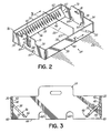
- the rack 24 has a quadrilateral frame 30 with two opposed longitudinally extending side walls 32 and opposed end walls 34.
- the rack 24 has no bottom or lower wall, and thus, fluids are able to pass through the rack 24.
- Two opposed support bars 36 are rigidly connected to the sides 32.
- the support bars 36 have a series of generally diamond shaped openings 38, and each of the openings 38 provides a subjacent support at one end of a lower edge 25 of a slide 26 shown in phantom.
- the diamond shape of the openings 38 minimizes contact between the slides 26 and the support bars 36.
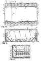
- each of the support bars 36 has an upper edge 40 that is rigidly connected to an inside surface 42 of the rack sides 32.
- the ends 41 of the support bars 36 do not extend to or contact the end walls 34, so that there is a small space 43 between the support bar ends 41 and the rack end walls 34.
- the support bar upper edge 40 is the only connection of the support bar 36 to the rack 24; and hence, the support bars 36 are cantilevered from the side walls 32.
- the support bars 36 extend angularly inward and downward from respective side wall inside surfaces 42 toward a bottom edge 48 of the side walls 32.
- each of the support bars 36 is movable or resiliently deflectable in response to a downward force to a distal end 46 of a respective support bar 36.
- the ends 34 of the rack 24 have a greater height than the sides 32; and therefore, the lower edges 44 of the ends 34 extend below the lower edges 48 of the sides 32.
- an opening or space 50 is provided over a length of the sides 32 between the side lower edge 48 and a plane defined by the lower edges 44 of the ends 34.
- the base 22 and cover 28 are substantially identical in construction.
- the base 22 and cover 28 may have different labeling either molded in or applied thereto.
- Each of the base 22 and the cover 28 has a major containment wall 55 with side walls 56 and end walls 58 extending around a periphery of the wall 55, thereby defining a cavity 61.
- each of the base 22 and cover 28 has a pair of spaced apart ribs 54 disposed on an inner surfaces 57 within the cavity 61.
- each of the base 22 and cover 28 has a first latch portion 60, for example, a projection or detent, extending inwardly from an inner surface 62 of each of the end walls 58.
- the rack 24 has a second latch portion 64, for example, a dimple or recess, disposed on an outer surface 66 of each of the end walls 34.
- the rack ends 34 have arched openings or notches 68 that reduce their stiffness and provide the rack ends 34 with some resiliency. Therefore, as the rack 24 is placed into the base 22, the rack ends 34 and/or the base ends 58 deflect slightly so that projections 60 ride over respective rack end surfaces 66 until the projections 60 snap into respective recesses 64. With the projections 60 disposed in the recesses 64 as shown in Fig. 6 , the rack 24 is now securely mounted in, and partially enclosed by, the base 22. There is sufficient clearance 65 between the ends of the ribs 54 and the rack ends 34 so that the lower edges 44 of the rack ends 34 rest directly on the inner surface 57 of the base wall 55.
- Each rack end 34 has a lower edge segment 69 that is slightly beveled downward and inward from an end wall outer surface 66 to a lower edge 44, so that the first latch portion or detent 60 more readily slides over the outer surface 66 toward the second latch portion or recess 64.
- the cover 28 With the rack 24 mounted in the base 22, the cover 28 is aligned with the base 22 and placed over the rack 24 and slides 26. The cover 28 is moved toward the base 22 while maintaining its alignment with the base 22. Referring to Fig. 5 , as a lower peripheral edge 74 of the cover 28 approaches, but before it contacts, an upper peripheral edge 76 of the base 22, the ribs 54 on a cover inner surface 59 contact upper edges 78 of the slides 26. In this embodiment, when the cover lower edge 74 is approximately 0.005 inches from the base upper edge 76, the ribs 54 contact the slide upper edges 78.
- the force of the ribs 54 contacting the slide upper edges 78 causes the resiliently cantilevered support bars 36 to deflect slightly downward toward the lower edge 48 of the rack side walls 32.
- the cover 28 is further moved until the cover lower edge 74 contacts the base upper edge 76, thereby limiting the force applied to the slide upper edges 78 and the deflection of the support bars 36.
- the slides 26 are clamped or secured between the cover ribs 54 and the support bars 36 of the rack 24.
- the rack 24 can be removed from the base 22 by either, direct manual manipulation or, a carrier can be inserted into the holes 81 and used to lift the rack 24 from the base 22.
- a carrier can be inserted into the holes 81 and used to lift the rack 24 from the base 22.
- the upper extending tabs 80 ( Fig. 1 ) on the rack ends 34 are pressed inward toward each other. The size of notches 68 determines the force necessary to slightly warp or bend the rack ends 34.
- the tabs 80 are pressed inward until the lower edges 70 of respective recesses 64 are clear of respective projections 60, and the rack 24 is moved out of the base 22. In that process, the lower edges 70 of the recesses 64 move past the latch projections 60 on the base 22, thereby unlatching the rack 24 from the base 22.
- the base 22 and cover 28 serve different functions, but they are substantially identical in construction. Therefore, as will be appreciated from the above description, the ribs 54 on the base 22 and the first latch portion 60 of the cover 28 ( Fig. 1 ) serve no purpose.
- the base 22, rack 24 and cover 28 are normally molded from a high density polyethylene material. However, as will be appreciated, those parts may be made of polypropylene, polycarbonate or any other plastic material that does not outgas. As will be appreciated, the parts can be made of other materials that are suitable for the intended use.
- the base 22, rack 24 and cover 28 are often made to be opaque in order to protect the slides from the adverse effects of light, if any.
- the supplier of the slides cuts the slides to the desired size, and cleans and dries them.
- the glass slides are used as specimen slides to hold and/or store samples of DNA.
- the supplier of the glass slides may coat the specimen slides in a liquid or vapor deposition process in which a DNA binding chemical provides the desired coating.
- the specimen slides 26 are loaded in the rack 24; and using the handles 79, the rack 24 is placed in a base 22.
- the latching members 60, 64 secure the rack 24 in the base 22 as previously described.
- the cover 28 is placed on the base 22 and the case 20 filled with slides 26 is vacuum sealed in a barrier bag, for example, an aluminum foil bag, so that the cover 28 is held firmly against the base 22. With the cover 28 firmly closed against the base 22, the slides 26 are clamped within the case 20; and the sealed case with the slides may be shipped to a customer using known commercial carriers.
- the vacuum package When received by a customer, for example, a DNA laboratory, the vacuum package is opened and the cover 28 is removed.
- the rack 24 with the slides 26 may then be removed from the base by depressing the ends 34 to release the latch members 60, 64.
- the handles 79 or a carrier (not shown) inserted into the handle holes 81 is used to pull the rack 24 from the base 22 and carry the rack 24 from one location to another.
- there are numerous procedures for processing the slides in the rack 24 The following are only a few examples of the processing options.
- the customer is able to preprocess the specimen slides while still in the rack 24. In this example, the rack 24 with the specimen slides 26 is dipped in one or more liquids.
- the rack 24 Prior to being placed in the centrifuge, the rack 24 is reinserted in a base 22.
- the base may be the same one that was used to ship the rack 24. Alternatively, it may be desirable to keep that base clean, and a different base can be used to hold the rack while in the centrifuge.
- the slides are often removed from the rack and placed in other equipment to be spotted, hybridized and scanned. If at any time during those processes, it is necessary to store the slides, they can again be placed in the rack 24.
- the rack is than placed in the base 22, and the cover 28 is placed on the base 22 to form a closed case 20.
- the cover 28 can be temporarily secured on the base by a surrounding tie or band, or the case can again be placed in a vacuum sealed package.
- the case can also be placed in the barrier bag in which it was received by the customer.
- the slide case 20 has a structure permitting slides to be preprocessed while contained within the rack 24. Further, when the cover 28 is applied over the base 22, the slides 26 are immobilized in the slide case 20. That immobilization in combination with the durability of the slide case 20 make it a suitable container for transporting the slides using commercial carriers. Thus, by substantially reducing the need and associated costs of removing and reloading the slides, the slide case 20 with the rack 24 is especially useful in environments where slides are subjected to preprocessing and/or where the slides must be transported to another location. As will be appreciated, the ability to process batches of slides in a rack 24 by the slide supplier as well as the customer, represents a substantial opportunity for cost savings. Further, the substantially identical structure of the base 22 and cover 28 permits both parts to be made from a single mold, thereby substantially reducing the cost of the molds needed to manufacture the case 20.
- the ribs 54 contact the slide upper edges 78 with an about 0.005 inch spacing between the cover lower edge 74 and the base upper edge 76.
- the spacing may vary depending on the size of the slides 26 and the case 20, the resiliency of the support bars 36, the desired securing force to be applied to the slide top edges 78, etc.
- the ribs 54 are shown as being of a continuous length and substantially parallel to the sides 32.
- the ribs may take the form of any shaped projections that are positioned so that they contact the slide upper edges.
- the ribs 54 or other projections can be continuous or discontinuous and oriented in any direction on the wall 55 of the cover 28, for example, the ribs can extend diagonally from corner to corner.
- two ribs 54 are shown, in an alternative embodiment, only one rib can be used.
- the ribs 54 can be eliminated and the inside surface of the wall 55 of the cover 28 used to contact the slide upper edges 78.
- the latch between the rack 24 and the base 22 is comprised of a projection on the base end wall 58 and a recess on the rack end wall 34.
- the location of those parts can be reversed with the projection being on the rack end wall 34 and the recess being on the base end wall 58.
- other latch mechanisms may be used, for example, the base may have a resilient finger that extends over an upper edge 76 of the rack end walls 34. While a latch is shown at the ends of the rack 24, in alternative embodiments, one or more latches may be operative with the rack sides 32 or a combination of the rack ends and sides. In further embodiments, fewer or more than two latches may be used to secure the rack 24 in the base 22.
- the sides 32 have a lesser height than the ends 34; and thus, a passage or space 50 for fluid drainage exists beneath the sides 32.
- the space 50 may be provided under only one of the sides walls 32 or under one or both of the end walls 34.
- both of the support bars 36 are described as being cantilevered from a side wall 32 by having only one edge connected to the side wall. Further, the diamond shaped openings in the support bars 36 may be replaced by any shaped hole or opening that supports the slides 26 in a desired manner.
- only a single movable support bar 36 can be used to support one end of the specimen slide and a fixed support is used to support the opposite end of the specimen slide.
- the fixed support can be a fixed support bar or other fixed supports such as V-shaped notches or slots molded on the inside surface of a rack side 32.
Landscapes
- Engineering & Computer Science (AREA)
- Mechanical Engineering (AREA)
- Physics & Mathematics (AREA)
- Chemical & Material Sciences (AREA)
- Analytical Chemistry (AREA)
- General Physics & Mathematics (AREA)
- Optics & Photonics (AREA)
- Sampling And Sample Adjustment (AREA)
Description
- This invention relates generally to a container for storing specimen slides and, more particularly, to an improved container for storing and transporting specimen slides.
- There are known storage containers for the bulk storage of frangible sheet material, such as specimen slides, e.g.
JP 52-118390 - In other situations, the slides must be shipped to another location. Known bulk storage containers are not able to protect the slides from the rigors of commercial shipping and transportation that are widely used to ship other items. Therefore, the slides must be removed from the bulk storage container and repackaged for shipment. Such special handling is not cost effective in most commercial environments. Thus, the repeated handling of each individual slide required by known bulk storage containers adds substantial cost to processes to which the slide is subjected.
- Consequently, there is a need for a bulk storage container that overcomes the disadvantages of known slide storage containers discussed above..
- The present invention provides a slide storage system that is simple in construction, flexible and durable in use. The slide storage system of the present invention secures the slides so that they do not chip in their supports, and the storage system is sufficiently durable that it can be used to transport the slides. Further, the storage system has a structure permitting slides to be processed while contained within the storage system. Thus, by substantially reducing the need and associated costs of removing and reloading the slides, the slide storage system of the present invention is especially useful in environments where slides are subjected to preprocessing and/or where the slides must be transported to another location.
- According to the principles of the present invention and in accordance with the described embodiments, the invention provides a rack for holding specimen slides. The rack has a frame with a first support bar having an opening adapted to support one end of a specimen slide. The first support bar has a first edge connected to a first side of the frame, so that the first support bar is movable with respect to the frame.
- In one aspect of this invention, the rack has a second support bar disposed in the frame substantially parallel to the first support bar. The second support bar has an opening for supporting an opposite end of the specimen slide and a first edge connected to an opposite side of the frame, so that the second support bar is movable with respect to the frame.
- In another embodiment of the invention, a slide case is provided for holding and transporting specimen slides. The slide case has a base having a first latch portion and a rack positionable adjacent the base with a second latch portion. As the rack is positioned adjacent the base, the first and second latch portions are placed in juxtaposition to releasably secure the rack in the base. A cover is positionable over the base such that the base and cover fully enclose the rack.
- In one aspect of this invention, one of the first and second latch portions is a projecting detent and the other latch portion is a recess. The latch being formed by the projecting detent being captured in the recess. In another embodiment of this invention, the cover has a rib that engages upper edges of the slides upon the cover being placed on the base. As the cover is fully engaged, the slides are pushed against a cantilevered support to slightly deflect the support and securely capture or clamp the specimen slides within the slide case. So secured, the case of specimen slides may then be shipped using commercial carriers without breaking or chipping the specimen slides.
- In another embodiment of the invention, a method is provided for inserting specimen slides into opposed supports, one of the supports having one edge attached to, and being movable with respect to, one side of a rack. Next, the rack holding the specimen slides is inserted into a base; and a cover is placed over the base so that the cover contacts upper edges of the specimen slides. As the cover is further moved toward the base, the cover simultaneously pushes the specimen slides against the one of the supports so that the one of the supports deflects, thereby securing the specimen slides in the slide case between the cover and the one of the supports.
- These and other objects and advantages of the present invention will become more readily apparent during the following detailed description taken in conjunction with the drawings herein.
-
-
Fig. 1 is a disassembled perspective view of a slide case in accordance with the principles of the present invention. -
Fig. 2 is perspective view of a slide rack used with the slide case ofFig. 1 . -
Fig. 3 is a cross-sectional view taken along line 3-3 ofFig. 2 and illustrates an end view of the slide rack. -
Fig. 4 is a top plan view of the slide rack ofFig. 2 . -
Fig. 5 is a cross-sectional end view of the assembled slide case ofFig. 1 . -
Fig. 6 is a centerline cross-sectional view of an end of the assembled slide case that illustrates the slide rack latch. - Referring to
Fig. 1 , aslide case 20 is comprised of a lower case orbase 22 that removably receives and supports aslide rack 24. Therack 24 individually supports and stores a plurality of flat, planar,rectangular slides 26, for example, glass specimen slides often used in laboratories. To facilitate picking up and carrying therack 24, therack 24 hashandles 79 formed by upward extendingtabs 80 andholes 81. An upper case or cover 28 fits over theslide rack 24 and when secured, abuts against thebase 22, thereby providing the enclosedslide case 20. Referring toFig. 2 , therack 24 has aquadrilateral frame 30 with two opposed longitudinally extendingside walls 32 and opposedend walls 34. Therack 24 has no bottom or lower wall, and thus, fluids are able to pass through therack 24. Twoopposed support bars 36 are rigidly connected to thesides 32. Thesupport bars 36 have a series of generally diamond shapedopenings 38, and each of theopenings 38 provides a subjacent support at one end of a lower edge 25 of aslide 26 shown in phantom. The diamond shape of theopenings 38 minimizes contact between theslides 26 and thesupport bars 36. - Referring to
Figs. 3 and4 , each of thesupport bars 36 has anupper edge 40 that is rigidly connected to aninside surface 42 of therack sides 32. However, theends 41 of thesupport bars 36 do not extend to or contact theend walls 34, so that there is asmall space 43 between thesupport bar ends 41 and therack end walls 34. Thus, the support barupper edge 40 is the only connection of thesupport bar 36 to therack 24; and hence, thesupport bars 36 are cantilevered from theside walls 32. Thesupport bars 36 extend angularly inward and downward from respective side wall insidesurfaces 42 toward abottom edge 48 of theside walls 32. Further, each of thesupport bars 36 is movable or resiliently deflectable in response to a downward force to adistal end 46 of arespective support bar 36. - The
ends 34 of therack 24 have a greater height than thesides 32; and therefore, thelower edges 44 of theends 34 extend below thelower edges 48 of thesides 32. Thus, an opening orspace 50 is provided over a length of thesides 32 between the sidelower edge 48 and a plane defined by thelower edges 44 of theends 34. - Referring to
Fig. 1 , thebase 22 andcover 28 are substantially identical in construction. Thebase 22 andcover 28 may have different labeling either molded in or applied thereto. Each of thebase 22 and thecover 28 has amajor containment wall 55 withside walls 56 andend walls 58 extending around a periphery of thewall 55, thereby defining acavity 61. Further, each of thebase 22 andcover 28 has a pair of spacedapart ribs 54 disposed on aninner surfaces 57 within thecavity 61. Theribs 54 extend lengthwise in a direction substantially parallel to thesides 56 and substantially perpendicular to theends 58; and therefore, when arack 24 ofslides 26 is mounted in thecase 20, theribs 54 are substantially perpendicular to planes of theslides 26. Further, each of thebase 22 and cover 28 has afirst latch portion 60, for example, a projection or detent, extending inwardly from an inner surface 62 of each of theend walls 58. Therack 24 has asecond latch portion 64, for example, a dimple or recess, disposed on anouter surface 66 of each of theend walls 34. - The rack ends 34 have arched openings or
notches 68 that reduce their stiffness and provide the rack ends 34 with some resiliency. Therefore, as therack 24 is placed into thebase 22, the rack ends 34 and/or the base ends 58 deflect slightly so thatprojections 60 ride over respective rack end surfaces 66 until theprojections 60 snap intorespective recesses 64. With theprojections 60 disposed in therecesses 64 as shown inFig. 6 , therack 24 is now securely mounted in, and partially enclosed by, thebase 22. There issufficient clearance 65 between the ends of theribs 54 and the rack ends 34 so that thelower edges 44 of the rack ends 34 rest directly on theinner surface 57 of thebase wall 55. Eachrack end 34 has alower edge segment 69 that is slightly beveled downward and inward from an end wallouter surface 66 to alower edge 44, so that the first latch portion ordetent 60 more readily slides over theouter surface 66 toward the second latch portion orrecess 64. - With the
rack 24 mounted in thebase 22, thecover 28 is aligned with thebase 22 and placed over therack 24 and slides 26. Thecover 28 is moved toward the base 22 while maintaining its alignment with thebase 22. Referring toFig. 5 , as a lowerperipheral edge 74 of thecover 28 approaches, but before it contacts, an upperperipheral edge 76 of thebase 22, theribs 54 on a coverinner surface 59 contactupper edges 78 of theslides 26. In this embodiment, when the coverlower edge 74 is approximately 0.005 inches from the baseupper edge 76, theribs 54 contact the slide upper edges 78. As thecover 28 is further moved toward thebase 22, the force of theribs 54 contacting the slideupper edges 78 causes the resiliently cantilevered support bars 36 to deflect slightly downward toward thelower edge 48 of therack side walls 32. Thecover 28 is further moved until the coverlower edge 74 contacts the baseupper edge 76, thereby limiting the force applied to the slideupper edges 78 and the deflection of the support bars 36. With thecover 28 fully closed on thebase 22, theslides 26 are clamped or secured between thecover ribs 54 and the support bars 36 of therack 24. - When the
cover 28 is moved away from thebase 22, thecover ribs 54 lose contact with the slideupper edges 78; and the support bars 36 move away from thelower edge 48 of therack side walls 32 and return to their original, unloaded and undeflected position. Therack 24 can be removed from the base 22 by either, direct manual manipulation or, a carrier can be inserted into theholes 81 and used to lift therack 24 from thebase 22. To remove therack 24 from thebase 22, the upper extending tabs 80 (Fig. 1 ) on the rack ends 34 are pressed inward toward each other. The size ofnotches 68 determines the force necessary to slightly warp or bend the rack ends 34. Thetabs 80 are pressed inward until thelower edges 70 ofrespective recesses 64 are clear ofrespective projections 60, and therack 24 is moved out of thebase 22. In that process, thelower edges 70 of therecesses 64 move past thelatch projections 60 on thebase 22, thereby unlatching therack 24 from thebase 22. It should be noted that thebase 22 and cover 28 serve different functions, but they are substantially identical in construction. Therefore, as will be appreciated from the above description, theribs 54 on thebase 22 and thefirst latch portion 60 of the cover 28 (Fig. 1 ) serve no purpose. - The
base 22,rack 24 and cover 28 are normally molded from a high density polyethylene material. However, as will be appreciated, those parts may be made of polypropylene, polycarbonate or any other plastic material that does not outgas. As will be appreciated, the parts can be made of other materials that are suitable for the intended use. Thebase 22,rack 24 and cover 28 are often made to be opaque in order to protect the slides from the adverse effects of light, if any. - In use, the supplier of the slides cuts the slides to the desired size, and cleans and dries them. Often, the glass slides are used as specimen slides to hold and/or store samples of DNA. In those applications, the supplier of the glass slides may coat the specimen slides in a liquid or vapor deposition process in which a DNA binding chemical provides the desired coating. The specimen slides 26 are loaded in the
rack 24; and using thehandles 79, therack 24 is placed in abase 22. The latchingmembers rack 24 in the base 22 as previously described. Next, thecover 28 is placed on thebase 22 and thecase 20 filled withslides 26 is vacuum sealed in a barrier bag, for example, an aluminum foil bag, so that thecover 28 is held firmly against thebase 22. With thecover 28 firmly closed against thebase 22, theslides 26 are clamped within thecase 20; and the sealed case with the slides may be shipped to a customer using known commercial carriers. - When received by a customer, for example, a DNA laboratory, the vacuum package is opened and the
cover 28 is removed. Therack 24 with theslides 26 may then be removed from the base by depressing the ends 34 to release thelatch members handles 79 or a carrier (not shown) inserted into the handle holes 81, is used to pull therack 24 from thebase 22 and carry therack 24 from one location to another. It should be noted that there are numerous procedures for processing the slides in therack 24. The following are only a few examples of the processing options. If desired, the customer is able to preprocess the specimen slides while still in therack 24. In this example, therack 24 with the specimen slides 26 is dipped in one or more liquids. Thereafter, the excess liquid is removed in a centrifuge. Prior to being placed in the centrifuge, therack 24 is reinserted in abase 22. The base may be the same one that was used to ship therack 24. Alternatively, it may be desirable to keep that base clean, and a different base can be used to hold the rack while in the centrifuge. After drying, the slides are often removed from the rack and placed in other equipment to be spotted, hybridized and scanned. If at any time during those processes, it is necessary to store the slides, they can again be placed in therack 24. The rack is than placed in thebase 22, and thecover 28 is placed on the base 22 to form aclosed case 20. As will be appreciated, thecover 28 can be temporarily secured on the base by a surrounding tie or band, or the case can again be placed in a vacuum sealed package. The case can also be placed in the barrier bag in which it was received by the customer. - The
slide case 20 has a structure permitting slides to be preprocessed while contained within therack 24. Further, when thecover 28 is applied over thebase 22, theslides 26 are immobilized in theslide case 20. That immobilization in combination with the durability of theslide case 20 make it a suitable container for transporting the slides using commercial carriers. Thus, by substantially reducing the need and associated costs of removing and reloading the slides, theslide case 20 with therack 24 is especially useful in environments where slides are subjected to preprocessing and/or where the slides must be transported to another location. As will be appreciated, the ability to process batches of slides in arack 24 by the slide supplier as well as the customer, represents a substantial opportunity for cost savings. Further, the substantially identical structure of thebase 22 and cover 28 permits both parts to be made from a single mold, thereby substantially reducing the cost of the molds needed to manufacture thecase 20. - While the invention has been illustrated by the description of one embodiment and while the embodiment has been described in considerable detail, there is no intention to restrict nor in any way limit the scope of the appended claims to such detail. Additional advantages and modifications will readily appear to those who are skilled in the art. For example, in the described embodiment, the
ribs 54 contact the slideupper edges 78 with an about 0.005 inch spacing between the coverlower edge 74 and the baseupper edge 76. As will be appreciated, the spacing may vary depending on the size of theslides 26 and thecase 20, the resiliency of the support bars 36, the desired securing force to be applied to the slidetop edges 78, etc. - In the described embodiment, the
ribs 54 are shown as being of a continuous length and substantially parallel to thesides 32. However, as will be appreciated, in an alternative embodiment, the ribs may take the form of any shaped projections that are positioned so that they contact the slide upper edges. Further, theribs 54 or other projections can be continuous or discontinuous and oriented in any direction on thewall 55 of thecover 28, for example, the ribs can extend diagonally from corner to corner. In addition, while tworibs 54 are shown, in an alternative embodiment, only one rib can be used. In a still further embodiment, theribs 54 can be eliminated and the inside surface of thewall 55 of thecover 28 used to contact the slide upper edges 78. - In the described embodiment, the latch between the
rack 24 and thebase 22 is comprised of a projection on thebase end wall 58 and a recess on therack end wall 34. As will be appreciated, in an alternative embodiment, the location of those parts can be reversed with the projection being on therack end wall 34 and the recess being on thebase end wall 58. In other embodiments, other latch mechanisms may be used, for example, the base may have a resilient finger that extends over anupper edge 76 of therack end walls 34. While a latch is shown at the ends of therack 24, in alternative embodiments, one or more latches may be operative with the rack sides 32 or a combination of the rack ends and sides. In further embodiments, fewer or more than two latches may be used to secure therack 24 in thebase 22. - In the described embodiment, the
sides 32 have a lesser height than theends 34; and thus, a passage orspace 50 for fluid drainage exists beneath thesides 32. As will be appreciated, in alternative embodiments, thespace 50 may be provided under only one of thesides walls 32 or under one or both of theend walls 34. - In addition, while the illustrated embodiment shows a case of a particular size for a particular number of slides; as will be appreciated, the claimed invention is applicable to a case of any size for any number of slides. Further, in the illustrated embodiment, both of the support bars 36 are described as being cantilevered from a
side wall 32 by having only one edge connected to the side wall. Further, the diamond shaped openings in the support bars 36 may be replaced by any shaped hole or opening that supports theslides 26 in a desired manner. - As will be appreciated, in an alternative embodiment, only a single
movable support bar 36 can be used to support one end of the specimen slide and a fixed support is used to support the opposite end of the specimen slide. The fixed support can be a fixed support bar or other fixed supports such as V-shaped notches or slots molded on the inside surface of arack side 32. With this embodiment, it may be desirable to mount the fixed support at a slightly lower elevation on arack side wall 32, such that when the slide is mounted in the rack and the cover is on the base, thereby deflecting the movable support bar, the slide is squarely supported with respect to the case. - Therefore, the invention in its broadest aspects is not limited to the specific details shown and described. Consequently, departures may be made from the details described herein without departing from the claims which follow.
Claims (13)
- A slide case (20) for holding and transporting a plurality of slides (26), the slide case comprising a base (22) having four walls connected to a bottom, a cover (28) having a projection (54) on an inner surface and positionable adjacent to and over the base, a rack (24) positionable within the base (22) and comprising a frame (30) having first and second sides (32), characterized in that the rack (24) is removably positionable within the base (22) and the first and second sides (32) are connected to opposed ends (34), and in that the rack further comprises a first support bar (36) with a first longitudinal edge (40) connected to, and extending lengthwise along, an inner surface (42) of the first side (32) to cantilever the first support bar (36) from the first side, the first support bar (36) being resiliently deflectable with respect to the first side (32) and having a first openings (38) for supporting first ends of the slides (26), and a second support bar (36) with a first longitudinal edge (40) connected to, and extending lengthwise along, an inner surface (42) of the second side (32) to cantilever the second support bar (36) from the second side, the second support bar (36) being deflectable with respect to the second side and having second openings (38) disposed opposite the first openings for supporting opposite ends of the slides, wherein upon the cover (28) being placed on the base, the projection (54) on the cover (28) presses against the slides (26) and deflects the first and second support bars (36) to secure the slides (26) between the rack (24) and the cover (28).
- The slide case in accordance with claim 1 wherein each of the first and second support bars (36) angles downward from a respective inner surface (42) toward lower edges of the ends (34) of the frame, each of the first and second support bars (36) forming an included acute angle with the respective inner surface (42) and having respective ends (41) that are spaced away from the ends (34) of the frame.
- The slide case in accordance with claims 1 or 2 wherein each of the openings (38) is substantially diamond shaped with two opposed corners of the diamond shape defining a line substantially perpendicular to the first edge (40) of a respective one of the first and second support bars (36).
- The slide case in accordance with claims 1 through 3 wherein the lower edges (44) of the ends (34) of the frame define a lowermost boundary of the frame, and the first and second sides (32) have respective lower edges (48) above the lowermost boundary of the frame.
- The slide case in accordance with claims 1 through 4 further comprising a first latch portion (60) disposed on the base (22), and a second latch portion (64) disposed on the frame (24) such that upon positioning the rack (30) within the base, the first and second latch portions (60, 64) are placed in juxtaposition to releasably secure the rack in the base.
- The slide case in accordance with claim 5 wherein the first latch portion is a detent (60) disposed on a wall (58) of the base (22), and the second latch portion is a recess (64) disposed in an end (34) of the frame, wherein the end of the frame is deflectable to permit the detent (60) to be moved with respect to the recess (68) between latched and unlatched positions.
- The slide case in accordance with claims 1 through 6 wherein the projection comprises at least one rib (54) extending substantially perpendicular to a plane of the slides (26).
- The slide case in accordance with claims 1 through 7 wherein the frame further comprises first and second holes (81), each hole extending through a different one of the ends (34) of the frame to facilitate picking up and carrying the rack (24).
- A method of handling slides comprising inserting the slides into opposed first and second supports (36) within a rack (24), the rack comprising a frame (30) formed by first and second sides (32) connected to respective first and second supports (36), characterized in that the first and second sides (32) are connected to opposed ends (34); in that the first support is a first support bar (36) having a first longitudinal edge (40) connected to, and extending lengthwise along, an inner surface (42) of the first side (32) to cantilever the first support bar (36) from the first side, the first support bar (36) being resiliently deflectable with respect to the first side (32) and having a first openings (38) for supporting first ends of the slides, and the second support is a second support bar (36) having a first longitudinal edge (40) connected to, and extending lengthwise along, an inner surface (42) of the second side (32) to cantilever the second support bar (36) from the second side, the second support bar (36) being resiliently deflectable with respect to the second side (32) and having second openings (38) disposed opposite the first openings for supporting opposite ends of the slides, and in that the method further comprises inserting the rack (24) with the slides (26) into a processing device, operating the processing device, and removing the rack (24) with the slides (26) from the processing device.
- The method in accordance with claim 9 further comprising inserting the rack (24) with the slides (26) into a centrifuge; and operating the centrifuge to cause fluid on the slides to flow off of the slides (26) and along a flow path beneath the frame (30).
- The method in accordance with claims 9 and 10 wherein each of the first and second support bars (36) angles downward from a respective inner surface (42) toward lower edges of the ends (34) of the frame, each of the first and second support bars (36) forming an included acute angle with the respective inner surface (42) and having respective ends (41) that are spaced away from the ends (34) of the frame and each opening (38) of the opposed pairs of openings being substantially diamond shaped with two opposed corners of the diamond shape defining a line substantially perpendicular to then first edge (40) of a respective one of the first and second support bars (36).
- The method in accordance with claim 9 through 11 wherein prior to the step of inserting the rack with the slides into a processing device, the method further comprises inserting and securing the rack (24) with the slides into a base (22) and placing over the base (22) a cover (28) having a projection (54) extending from an internal surface, the projection (54) pressing against upper edges of respective slides and deflecting the first and second support bars (36) to secure the slides between the rack (24) and the cover (28), thereby allowing transportation of the slides in the rack (24) within the base (22) and cover (28).
- The method in accordance with claim 12 further comprising removing the cover (28) from the base (22), and removing the rack (24) with the slides (26) from the base (22).
Applications Claiming Priority (3)
| Application Number | Priority Date | Filing Date | Title |
|---|---|---|---|
| US10/024,269 US7160514B2 (en) | 2001-12-18 | 2001-12-18 | Slide case with removable rack |
| US24269 | 2001-12-18 | ||
| PCT/US2002/039669 WO2003052484A2 (en) | 2001-12-18 | 2002-12-11 | Slide case with removable rack |
Publications (2)
| Publication Number | Publication Date |
|---|---|
| EP1456707A2 EP1456707A2 (en) | 2004-09-15 |
| EP1456707B1 true EP1456707B1 (en) | 2009-02-11 |
Family
ID=21819730
Family Applications (1)
| Application Number | Title | Priority Date | Filing Date |
|---|---|---|---|
| EP02795830A Expired - Lifetime EP1456707B1 (en) | 2001-12-18 | 2002-12-11 | Slide case with removable rack |
Country Status (5)
| Country | Link |
|---|---|
| US (1) | US7160514B2 (en) |
| EP (1) | EP1456707B1 (en) |
| AU (1) | AU2002360564A1 (en) |
| DE (1) | DE60231145D1 (en) |
| WO (1) | WO2003052484A2 (en) |
Cited By (1)
| Publication number | Priority date | Publication date | Assignee | Title |
|---|---|---|---|---|
| CN103241472A (en) * | 2012-02-12 | 2013-08-14 | 高新春 | Glass slide specimen box |
Families Citing this family (25)
| Publication number | Priority date | Publication date | Assignee | Title |
|---|---|---|---|---|
| EP1417033A4 (en) * | 2001-08-16 | 2010-06-23 | Ge Healthcare Bio Sciences Ab | SUPPORTS FOR THE PARALLEL PROCESSING OF OLIGONUCLEOTIDE CHIPS |
| US20030183337A1 (en) * | 2002-03-28 | 2003-10-02 | James Fordemwalt | Apparatus and method for use of optical diagnostic system with a plasma processing system |
| DE10240736B4 (en) * | 2002-08-30 | 2004-07-22 | Schott Glas | Containers for holding plates |
| DE10251650B4 (en) * | 2002-10-30 | 2005-05-04 | Schott Ag | Containers for storing and transporting delicate platelike articles and use of such |
| US6765734B1 (en) * | 2003-03-14 | 2004-07-20 | Hinds Instruments, Inc. | Adjustable sample holder for optical equipment |
| US20050126935A1 (en) * | 2003-12-15 | 2005-06-16 | Dri Mark Products, Inc. | Marker holding assembly |
| US20050194279A1 (en) * | 2004-03-08 | 2005-09-08 | Coppola Frank T. | Method and apparatus for packaging glass substrates |
| US20070029268A1 (en) * | 2005-08-04 | 2007-02-08 | King Yuan Electronics Co., Lt | Wafer cassette used in high temperature baking process |
| US7562776B1 (en) * | 2005-09-27 | 2009-07-21 | Melynda Bautista Ludwig | Slide holder for staining specimens disposed on microscope slides |
| US7746465B2 (en) * | 2007-01-18 | 2010-06-29 | Hinds Instruments, Inc. | Sample holder for an optical element |
| JP5048016B2 (en) * | 2009-04-20 | 2012-10-17 | 村角工業株式会社 | Preparation slide case |
| DE102010062543B4 (en) | 2010-12-07 | 2019-03-28 | Leica Biosystems Nussloch Gmbh | Holding device for holding slides |
| US8844732B2 (en) * | 2012-08-03 | 2014-09-30 | Nanya Technology Corporation | Cassette tray and carrier module |
| US9581800B2 (en) * | 2014-11-21 | 2017-02-28 | General Electric Company | Slide holder for detection of slide placement on microscope |
| USD799057S1 (en) * | 2015-12-18 | 2017-10-03 | Abbott Laboratories | Slide rack |
| USD802787S1 (en) * | 2015-12-18 | 2017-11-14 | Abbott Laboratories | Slide carrier |
| USD782695S1 (en) * | 2015-12-18 | 2017-03-28 | Abbott Laboratories | Slide carrier |
| USD799058S1 (en) * | 2016-02-18 | 2017-10-03 | Abbott Laboratories | Slide caddy |
| CN108709998B (en) * | 2018-07-26 | 2024-05-14 | 湖南莱博赛医用机器人有限公司 | Glass slide box and cell analysis equipment |
| CN110861838A (en) * | 2018-08-28 | 2020-03-06 | 鸿富锦精密工业(深圳)有限公司 | Buffer packaging device |
| US10898981B2 (en) * | 2018-12-19 | 2021-01-26 | Amada Holdings Co., Ltd. | Workpiece storage device and workpiece loading method |
| CN113955322B (en) * | 2021-11-13 | 2022-10-28 | 深圳恩泽瑞显示科技有限公司 | LCD glass turnover conveyer |
| CN113998289B (en) * | 2021-11-18 | 2023-04-11 | 中国人民解放军陆军特色医学中心 | Transport box capable of protecting tumor slices |
| CN115521852B (en) * | 2022-09-09 | 2025-11-07 | 北京工道风行智能技术有限公司 | A semi-automatic detection storehouse for nucleic acid detection box is incorporated |
| CN118651513B (en) * | 2024-08-20 | 2024-10-25 | 河南纳腾能源科技有限公司 | Sample classified storage equipment for environmental monitoring |
Family Cites Families (8)
| Publication number | Priority date | Publication date | Assignee | Title |
|---|---|---|---|---|
| US3960268A (en) * | 1975-09-15 | 1976-06-01 | Villa Precision, Inc. | Frame for supporting frangible sheet materials |
| JPS52118390A (en) | 1976-03-26 | 1977-10-04 | Senken Kk | Iccwafer transporting container |
| US4481246A (en) * | 1982-11-15 | 1984-11-06 | Sybron Corporation | Microscope slide with raised marking surface |
| US4679914A (en) * | 1985-09-13 | 1987-07-14 | Erie Scientific Company | Microscope slide with top and bottom marking surfaces |
| US5021218A (en) * | 1990-01-19 | 1991-06-04 | Dlp, Inc. | Apparatus for transporting specimen slides |
| US5279800A (en) * | 1992-11-25 | 1994-01-18 | C/T Med-Systems Ltd., Inc. | Dental cassette kit |
| US5571721A (en) * | 1994-05-05 | 1996-11-05 | Erie Scientific Company | Improved biological culture slide and method of making same |
| US5736102A (en) * | 1996-02-21 | 1998-04-07 | Biomerieux Vitek, Inc. | Test sample positioning system |
-
2001
- 2001-12-18 US US10/024,269 patent/US7160514B2/en not_active Expired - Lifetime
-
2002
- 2002-12-11 WO PCT/US2002/039669 patent/WO2003052484A2/en not_active Ceased
- 2002-12-11 EP EP02795830A patent/EP1456707B1/en not_active Expired - Lifetime
- 2002-12-11 DE DE60231145T patent/DE60231145D1/en not_active Expired - Lifetime
- 2002-12-11 AU AU2002360564A patent/AU2002360564A1/en not_active Abandoned
Cited By (1)
| Publication number | Priority date | Publication date | Assignee | Title |
|---|---|---|---|---|
| CN103241472A (en) * | 2012-02-12 | 2013-08-14 | 高新春 | Glass slide specimen box |
Also Published As
| Publication number | Publication date |
|---|---|
| WO2003052484A2 (en) | 2003-06-26 |
| AU2002360564A8 (en) | 2003-06-30 |
| EP1456707A2 (en) | 2004-09-15 |
| AU2002360564A1 (en) | 2003-06-30 |
| DE60231145D1 (en) | 2009-03-26 |
| US7160514B2 (en) | 2007-01-09 |
| US20030111373A1 (en) | 2003-06-19 |
| WO2003052484A3 (en) | 2004-01-29 |
Similar Documents
| Publication | Publication Date | Title |
|---|---|---|
| US7160514B2 (en) | Slide case with removable rack | |
| US7658887B2 (en) | Pipette tip grid with lock mechanism | |
| US4880116A (en) | Robotic accessible wafer shipper assembly | |
| US4817795A (en) | Robotic accessible wafer shipper assembly | |
| US4718552A (en) | Disk shipper and transfer tray | |
| US4752007A (en) | Disk shipper | |
| EP0910114B1 (en) | Wafer shipper and package | |
| EP0530332B1 (en) | Cushioned cover for wafer container | |
| US4577760A (en) | Apparatus for supporting pipette tips | |
| US4450960A (en) | Package | |
| CA1107692A (en) | Wafer packaging system | |
| CA2264366A1 (en) | Archival storage tray for multiple test tubes | |
| EP0400784A2 (en) | A sealable contamination-proof container package for wafers | |
| EP0774161B1 (en) | Wafer cushions for wafer shipper | |
| JPS61502326A (en) | substrate media carrier | |
| JP2010538924A (en) | Centrifuge tube rack | |
| US6918738B2 (en) | Stackable sample holding plate with robot removable lid | |
| JP2791971B2 (en) | Wafer basket in wafer storage container | |
| US5203454A (en) | Method and apparatus for transporting sensitive electronic components | |
| EP0343762A2 (en) | Substrate package | |
| JP3968142B2 (en) | Support groove structure of semiconductor wafer in packaging container | |
| US5909812A (en) | Container for storing and transporting leadframes | |
| JPH092563A (en) | Disc case | |
| JPS63178972A (en) | Product container | |
| CN116391025A (en) | Shelf for holding a plurality of culture dishes and transport package having the same |
Legal Events
| Date | Code | Title | Description |
|---|---|---|---|
| PUAI | Public reference made under article 153(3) epc to a published international application that has entered the european phase |
Free format text: ORIGINAL CODE: 0009012 |
|
| 17P | Request for examination filed |
Effective date: 20040614 |
|
| AK | Designated contracting states |
Kind code of ref document: A2 Designated state(s): AT BE BG CH CY CZ DE DK EE ES FI FR GB GR IE IT LI LU MC NL PT SE SI SK TR |
|
| AX | Request for extension of the european patent |
Extension state: AL LT LV MK RO |
|
| RIN1 | Information on inventor provided before grant (corrected) |
Inventor name: CHOUINARD, RICHARD, J. Inventor name: COSBY, N., GUY Inventor name: MOORE, DAVID, J. |
|
| GRAP | Despatch of communication of intention to grant a patent |
Free format text: ORIGINAL CODE: EPIDOSNIGR1 |
|
| GRAS | Grant fee paid |
Free format text: ORIGINAL CODE: EPIDOSNIGR3 |
|
| GRAS | Grant fee paid |
Free format text: ORIGINAL CODE: EPIDOSNIGR3 |
|
| GRAA | (expected) grant |
Free format text: ORIGINAL CODE: 0009210 |
|
| AK | Designated contracting states |
Kind code of ref document: B1 Designated state(s): DE FR GB SE |
|
| REG | Reference to a national code |
Ref country code: GB Ref legal event code: FG4D |
|
| REF | Corresponds to: |
Ref document number: 60231145 Country of ref document: DE Date of ref document: 20090326 Kind code of ref document: P |
|
| PG25 | Lapsed in a contracting state [announced via postgrant information from national office to epo] |
Ref country code: SE Free format text: LAPSE BECAUSE OF FAILURE TO SUBMIT A TRANSLATION OF THE DESCRIPTION OR TO PAY THE FEE WITHIN THE PRESCRIBED TIME-LIMIT Effective date: 20090511 |
|
| PLBE | No opposition filed within time limit |
Free format text: ORIGINAL CODE: 0009261 |
|
| STAA | Information on the status of an ep patent application or granted ep patent |
Free format text: STATUS: NO OPPOSITION FILED WITHIN TIME LIMIT |
|
| 26N | No opposition filed |
Effective date: 20091112 |
|
| REG | Reference to a national code |
Ref country code: FR Ref legal event code: PLFP Year of fee payment: 14 |
|
| REG | Reference to a national code |
Ref country code: FR Ref legal event code: PLFP Year of fee payment: 15 |
|
| REG | Reference to a national code |
Ref country code: FR Ref legal event code: PLFP Year of fee payment: 16 |
|
| REG | Reference to a national code |
Ref country code: DE Ref legal event code: R082 Ref document number: 60231145 Country of ref document: DE Representative=s name: 2K PATENTANWAELTE BLASBERG KEWITZ & REICHEL PA, DE |
|
| REG | Reference to a national code |
Ref country code: DE Ref legal event code: R082 Ref document number: 60231145 Country of ref document: DE Representative=s name: 2K PATENTANWAELTE BLASBERG KEWITZ & REICHEL PA, DE Ref country code: DE Ref legal event code: R081 Ref document number: 60231145 Country of ref document: DE Owner name: NEW ERIE SCIENTIFIC LLC, PORTSMOUTH, US Free format text: FORMER OWNER: ERIE SCIENTIFIC COMPANY, PORTSMOUTH, N.H., US |
|
| REG | Reference to a national code |
Ref country code: GB Ref legal event code: 732E Free format text: REGISTERED BETWEEN 20190808 AND 20190814 |
|
| REG | Reference to a national code |
Ref country code: GB Ref legal event code: 732E Free format text: REGISTERED BETWEEN 20191219 AND 20191224 |
|
| PGFP | Annual fee paid to national office [announced via postgrant information from national office to epo] |
Ref country code: DE Payment date: 20211227 Year of fee payment: 20 Ref country code: GB Payment date: 20211227 Year of fee payment: 20 Ref country code: FR Payment date: 20211227 Year of fee payment: 20 |
|
| REG | Reference to a national code |
Ref country code: DE Ref legal event code: R071 Ref document number: 60231145 Country of ref document: DE |
|
| REG | Reference to a national code |
Ref country code: GB Ref legal event code: PE20 Expiry date: 20221210 |
|
| PG25 | Lapsed in a contracting state [announced via postgrant information from national office to epo] |
Ref country code: GB Free format text: LAPSE BECAUSE OF EXPIRATION OF PROTECTION Effective date: 20221210 |