EP1456483B1 - Plateformed building element comprising zigzag shaped lamellae - Google Patents
Plateformed building element comprising zigzag shaped lamellae Download PDFInfo
- Publication number
- EP1456483B1 EP1456483B1 EP02793671A EP02793671A EP1456483B1 EP 1456483 B1 EP1456483 B1 EP 1456483B1 EP 02793671 A EP02793671 A EP 02793671A EP 02793671 A EP02793671 A EP 02793671A EP 1456483 B1 EP1456483 B1 EP 1456483B1
- Authority
- EP
- European Patent Office
- Prior art keywords
- building element
- plateformed
- lamellae
- crossbar
- forming
- Prior art date
- Legal status (The legal status is an assumption and is not a legal conclusion. Google has not performed a legal analysis and makes no representation as to the accuracy of the status listed.)
- Expired - Lifetime
Links
- 238000010276 construction Methods 0.000 claims abstract description 12
- 239000002023 wood Substances 0.000 claims abstract description 11
- 239000002657 fibrous material Substances 0.000 claims abstract description 7
- 238000005192 partition Methods 0.000 claims description 2
- 239000000463 material Substances 0.000 description 14
- XEEYBQQBJWHFJM-UHFFFAOYSA-N Iron Chemical compound [Fe] XEEYBQQBJWHFJM-UHFFFAOYSA-N 0.000 description 12
- 230000001413 cellular effect Effects 0.000 description 7
- 238000004519 manufacturing process Methods 0.000 description 7
- 229910052742 iron Inorganic materials 0.000 description 6
- 239000003292 glue Substances 0.000 description 4
- 235000000396 iron Nutrition 0.000 description 4
- 238000000034 method Methods 0.000 description 3
- 238000004026 adhesive bonding Methods 0.000 description 2
- 238000004873 anchoring Methods 0.000 description 2
- 238000009413 insulation Methods 0.000 description 2
- 238000005304 joining Methods 0.000 description 2
- 239000002184 metal Substances 0.000 description 2
- 229910052751 metal Inorganic materials 0.000 description 2
- 239000002344 surface layer Substances 0.000 description 2
- 241000446313 Lamella Species 0.000 description 1
- 230000002860 competitive effect Effects 0.000 description 1
- 239000013013 elastic material Substances 0.000 description 1
- 230000001747 exhibiting effect Effects 0.000 description 1
- 238000004079 fireproofing Methods 0.000 description 1
- 238000009434 installation Methods 0.000 description 1
- 239000012774 insulation material Substances 0.000 description 1
- 239000010410 layer Substances 0.000 description 1
- 238000012986 modification Methods 0.000 description 1
- 230000004048 modification Effects 0.000 description 1
- 230000010355 oscillation Effects 0.000 description 1
- 239000003351 stiffener Substances 0.000 description 1
Images


Classifications
-
- E—FIXED CONSTRUCTIONS
- E04—BUILDING
- E04B—GENERAL BUILDING CONSTRUCTIONS; WALLS, e.g. PARTITIONS; ROOFS; FLOORS; CEILINGS; INSULATION OR OTHER PROTECTION OF BUILDINGS
- E04B5/00—Floors; Floor construction with regard to insulation; Connections specially adapted therefor
- E04B5/02—Load-carrying floor structures formed substantially of prefabricated units
- E04B5/12—Load-carrying floor structures formed substantially of prefabricated units with wooden beams
-
- E—FIXED CONSTRUCTIONS
- E04—BUILDING
- E04C—STRUCTURAL ELEMENTS; BUILDING MATERIALS
- E04C2/00—Building elements of relatively thin form for the construction of parts of buildings, e.g. sheet materials, slabs, or panels
- E04C2/30—Building elements of relatively thin form for the construction of parts of buildings, e.g. sheet materials, slabs, or panels characterised by the shape or structure
- E04C2/34—Building elements of relatively thin form for the construction of parts of buildings, e.g. sheet materials, slabs, or panels characterised by the shape or structure composed of two or more spaced sheet-like parts
- E04C2/3405—Building elements of relatively thin form for the construction of parts of buildings, e.g. sheet materials, slabs, or panels characterised by the shape or structure composed of two or more spaced sheet-like parts spaced apart by profiled spacer sheets
-
- E—FIXED CONSTRUCTIONS
- E04—BUILDING
- E04C—STRUCTURAL ELEMENTS; BUILDING MATERIALS
- E04C2/00—Building elements of relatively thin form for the construction of parts of buildings, e.g. sheet materials, slabs, or panels
- E04C2/30—Building elements of relatively thin form for the construction of parts of buildings, e.g. sheet materials, slabs, or panels characterised by the shape or structure
- E04C2/34—Building elements of relatively thin form for the construction of parts of buildings, e.g. sheet materials, slabs, or panels characterised by the shape or structure composed of two or more spaced sheet-like parts
- E04C2/3405—Building elements of relatively thin form for the construction of parts of buildings, e.g. sheet materials, slabs, or panels characterised by the shape or structure composed of two or more spaced sheet-like parts spaced apart by profiled spacer sheets
- E04C2002/3444—Corrugated sheets
- E04C2002/345—Corrugated sheets with triangular corrugations
-
- E—FIXED CONSTRUCTIONS
- E04—BUILDING
- E04C—STRUCTURAL ELEMENTS; BUILDING MATERIALS
- E04C2/00—Building elements of relatively thin form for the construction of parts of buildings, e.g. sheet materials, slabs, or panels
- E04C2/30—Building elements of relatively thin form for the construction of parts of buildings, e.g. sheet materials, slabs, or panels characterised by the shape or structure
- E04C2/34—Building elements of relatively thin form for the construction of parts of buildings, e.g. sheet materials, slabs, or panels characterised by the shape or structure composed of two or more spaced sheet-like parts
- E04C2002/3477—Building elements of relatively thin form for the construction of parts of buildings, e.g. sheet materials, slabs, or panels characterised by the shape or structure composed of two or more spaced sheet-like parts spaced apart by tubular elements parallel to the sheets
Definitions
- the present invention relates to aigned building element for the construction of floor structures and/or walls and consisting of wood or other fibrous material with members connecting inner and outer sides positioned at a mutual distance, the connecting members formed from snapped crossbar-forming lamellae distributed essentially along the whole surface range of the building element, extending at an inclination and/or curved into zigzag patterns and distributed along said formed building element and forming paired channels therein.
- Plateformed building elements used in floor structures and wall systems in buildings are manufactured manually at the building site or prefabricated in a factory. Thereby, pairs of plates are separated at a mutual distance by crossbars.
- Previously known building elements of said kind consist of lamellae, perpendicular to the surface layer of the building element, forming square or rectangular cells.
- SE 3384704 and DE 1941368 disclose previously known building elements exhibiting stiffeners in the form of connections formed from relieved lamellae extending in folds or waves.
- trusses Building elements with trusses are also known wherein said trusses are formed from inclined plates or metal rods.
- FR 2 793 827 Al discloses trusses composed of angulated plates, but this concerns only a beam thus formed and not wholeaded building elements.
- WO 99/18304 , EP 0 282 424 A1 and US 4, 475, 328 A disclose trusses forming parallel spaced beams from zigzag-shaped spacing members. The construction of acquiredd elements then takes place manually with a multitude of such beams, which, apart from the fact that the building element acquires limited strength, also may be time-consuming and labor-intensive.
- any snapped building element comprising inclining and/or curved channel-forming lamellae attached to lateral crossbars through nails or screws whereby the anchoring joints are formed from U-shaped receptacles to which the crossbars can be joined.
- Known embodiments comprise building elements formed from plates on opposite sides of inclined or curved channel-forming lamellae; and which lamellae and plates are joined together by gluing.
- the purpose of the present invention is therefore among other things to achieve an improved building element of the initially mentioned kind that allows reduction of the total cost for more efficient manufacturing in a factory as well as better utilization of the supporting capacity of the material, furthermore giving the building element a low tare weight.
- the advantage in using beams rather than plates on at least one side of the building element is that the building element is formed essentially only from the centrally situated lamellae arranged to extend at an angle with respect to each other and to be able, in connected mode, to receive essentially the total load of said building element.
- connection of the building element to lateral beams takes place through U-shaped angulated anchoring joints comprising pairs of U-shaped receptacles for angulated lamellae and for connection to angulated beams as shown, for example, in Fig. 6 .
- the building element as defined in the new claim 1 cannot be considered obvious to a person skilled in the are based on what has been shown to be previously known through the two cited novelty referrals SE 384,708 and DE 1941368 .
- the present wall and floor structure system has a technical level and thereby the right economical qualities. Through new products with new thinking, such as this building-frame intended to be supplemented by other working methods, wood will become more competitive and its value will be increased with great potential. According to calculation, the floor structure system has load bearing capacity at rupture limit conditions and dynamic stiffness towards oscillations at usage limit conditions, in both cases a good measure of overcapacity.
- Inclining the beams and joining them at the upper and lower edges opens up great opportunity in the future for building structures of wood.
- the system demonstrates the enormous strength of wood in a co-operating cellular system.
- the manufacturing of the building elements is to be performed as standardized as possible, with a width of 1,20 m or 2,40 m, but the length may be varied due to the manufacturing method.
- the building elements can also be spliced in their longitudinal direction.
- the proposed building element for this purpose is characterized primarily in that the lamellae are mounted, for instance, at an inclined angle in the form of one or more sine curves absorbing the tensile and compressive forces with a zero in the center of the building elements. Thereby, the forces will co-operate with the outer shell in an efficient manner.
- the core of the floor structure element or wall element is designed as a trigonometric shape so that the load bearing capacity increases exceptionally in co-operation with the design of the outer shell.
- the forces co-operate in the way of a sine curve. This is kept together through crossbars, boards or plate material, perpendicularly along the upper and lower edges. At the breaking points, the material is fixed together. It forms long triangular-shaped channels along the crossbars or beams along the lower as well as the upper edges.
- the characteristics of the wall and floor structure fulfill many demands.
- the strength of the elements in all directions is unique.
- a good tightness is obtained due to the connection of the crossbars and beams.
- the crossbars are now inclined or curving towards each other with-connection in the short sides of the crossbars against the-outer and inner edges of the wall. In this way a zigzag pattern is achieved in the wall system, endowing the wall with many good qualities such as the load bearing capacity, soundproofness, fireproofness, tightness, and very good stability in all directions.
- the beams are positioned inclining towards each other but are connected to each other at the upper end of the beams. This applies also for the lower ends.
- the connection can be through specially designed metal shoes. Plates, crossbars or boards functioning to keep the building element together may also be used.
- the present invention relates to a cellularly divided trigonometric building element in which the cells are kept together along the upper and lower edges through plate material or similar.
- the invention concerns such a building element of the kind comprising a multitude of cells of similar appearance, next to and mounted towards each other through gluing or similar.
- the inclined lamellae form a number of identical cells in the building element
- the pattern of the various cells form longitudinal channels in the longitudinal direction of the building element.
- Each of the different cellular--systems has different properties, but it is the most cost efficient cellular system in relation to the most desirable properties that will decide the manufacturing system, which is to be as industrialized as possible.
- the material in the upper and lower edges of the building element may be different, for example, plate material, boards or crossbars made of wood or other fibrous material mounted with glue or in similar ways.
- Drawing irons may also be used at the lower edge of the elements in order to increase the load bearing capacity of the building elements.These drawing irons may be used to pull the building elements together into large continuous floor structures during assembly at the construction site.
- Prefabricated building element of said kind are utilized above all as load-bearing floor structures and roof elements in the building of one-family houses, apartment buildings, economy buildings, and industrial premises etc. They can, however, also be utilized for other purposes, for instance, as bearing wall elements.
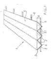
- Fig. 1 shows a perspective view of a snapped cell-shaped building element 1 according to a first exemplifying embodiment of the invention with triangularly inclined lamellae 2 connected-for mounting along the upper edge 3 and-the lower edge 4.
- materials of different kind are used, such as board plates 5, cross bars or iron struts.
- tie-rods 6 or crossbars are mounted.
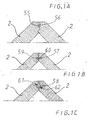
- Fig. 1A-1C show enlarged end views describing the design of the lamellae during their mounting. All lamellae 2 are identical elements also during mounting between the elements and the design can be greatly varied. The objective is to attain a joint area as large as possible. Therefore, a number of varieties are chosen to be shown: 1A shows a dented embodiment, 1B shows a groove and tongue embodiment, and 1C shows a round stave embodiment. All embodiments are mounted with glue, screws, nails or similar.
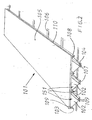
- Fig. 2 shows a perspective view of a snapped cell forming building element 101 according to an exemplifying embodiment of the invention with triangularly inclined lamella 102 joined together for mounting at the upper 103 and lower 104 edges.
- The.lamellae 102 are built from triangular crossbars 107, 108 with milled grooves 109 for mounting of inclinedised lamellae 102 between the triangular crossbars according to Fig. 2 .
- the upper face of the building element may consist of plate material 105, boards, crossbars or iron struts 106. The same applies to the lower face 104.
- Fig. 2A shows an enlargement of two snapped building elements 101 during lateral assembly.
- the building elements are not completely joined in order to show that the tongue (the guide bar) 111 is mounted in a longitudinal groove 110 in a divided triangular crossbar 108 in each building element 101.
- the procedure forms a triangular crossbar of equal size when joining the building elements 101.
- the building element 101 is constructed from triangular lamellae 107, grooved 109 for mounting of inclined snapped lamellae 102. Between the crossbars at the outer edges of the building element 101, the triangular crossbars 108 are provided with an extra groove 110 in order to receive an elongated tongue 111 during assembly of the building elements 101.
- Fig. 3 shows a perspective view of another building element 201 according to an exemplifying embodiment of the invention.
- the embodiment is based upon a plate shaped to form a wave-shaped sine curve, and cells are thereby connected through an outer layer on the upper and lower faces of the building element.
- the upper face of the building element may be constructed from plate material 205, boards, crossbars or iron struts 206. The same applies to the lower face 204.
- Fig. 3A shows a small part of the enlargement of two building elements 201 during connection. They are not completely joined in order to demonstrate that the tongue (the guide bar) 211 is mounted in a guide groove 209 and holding the elements 201, 201 together.
- Fig. 4 shows a perspective view of a cell-shaped building element 301 according to an exemplifying embodiment of the invention-with a geometrical construction forming a cellular system with lamellae.
- Said building element forms two wave-shaped sine curves that absorb compressive and tensile forces in the whole cellular system.
- Plate material 305, 306, boards, crossbars or iron struts are mounted in the upper and lower parts of the building element.
- Fig. 4A shows an enlargement of two building elements during connection.
- the building elements are not completely joined in order to demonstrate that the tongue (guide bar) function is mounted in grooves in the lower and upper parts of the building element.
- Fig. 5 shows a perspective view of a cell-shaped building element 401 according to an exemplifying embodiment of the invention with a geometrical construction forming a cellular system with circular lamellae.
- Said building element forms two wave-shaped sine curves that absorb compressive and tensile forces in the whole cellular system.
- the inclined arced lamellae 402, together with the surface layer 405; 406, form a strong building element that absorbs great loads. Plate material, boards, crossbars or iron struts are mounted in the upper and lower parts of the building element.
- Fig. 5A shows an enlargement of two building elements during connection.
- the building elements are-not completely joined in order to demonstrate that the tongue (guide bar) is mounted in grooves in the lower and upper parts of the building element.
- Insulation material I can be received in cavities 450 in said building element 401 as well as inside the cells 451.
- Fig. 6 shows examples of a floor structure element 501 constructed from a multitude of elongated inclined plate-shaped lamellae 502. Attached perpendicular floor girders 505 and roof girders 506, respectively, are received above and below said lamellae 502. At the bottom of the floor structure, attachment can take place through tie rods (not shown) in order to absorb-greater load.
- Attachment of the floor girders 505 and the roof girders 506 may take place through attachment members 512, 513 in the form of U-shaped assembling irons and angularly perpendicular anchor plates.
- the invention relates to aigned building element 1; 101, 201, 301, 401, 501, 601, intended for the construction of floor structures and/or walls. It consists of wood or other fibrous material with members 2; 102; 202; 302; 402; 502 connecting two inner and outer faces 5; 105; 205; 305; 905; 505, and 6; 106; 20G; 306; 406; 506, respectively, positioned at a mutual distance A from each other.
- the connecting members are formed from plate-shaped lamellae distributed essentially along the whole surface range of the building element, extending inclined and/or curved in zigzag patterns and distributed along said formed building element forming pairs of parallel channels 51; 151; 251; 351; 451; 551.
- connections between the lamellae 2; 102; 202; 302; 402; 502 may be formed from interacting recesses 55, 56 and/or from ledge-shaped rods 57, 58 arranged to be received in groove-shaped notches 59, 60; 61, 62 in said crossbar-forming lamellae 2 as shown in Fig. 1A-1C .
- Said regularly arranged lamellae 2; 102; 302; 402; 502 are attached to each other as well as to said paired surface plates.
- the crossbar-forming lamellae 102 are received with their facing edges in grooves 109 at ledge-shaped connectors 107, 108.
- said connectors have a triangular cross section, and are attached through glue joints, screw or nail joints to adjacent connecting plates etc 105; 106.
- said grooves 109 are arranged to extend in pairs perpendicularly with respect to each other.
- the building element 201 shown in Fig. 3 exhibits connective members 202 forming a wave-shaped longitudinal partition in the formed building element 201.
- the connective members 302; 402, arranged at the thereby formed building elements 301; 401 are groove-shaped when viewed along the surface extension of the building element and extend in parallel with respect to each other, In the attached mode, they form channels 351; 451 with a round or multihedral cross section.
- the crossbar-forming lamellae are attached to the strips and/or beams that extend perpendicularly to said lamellae using glue, nails, or screws.
- Fig. 6-6C show how such nail joints 512 are formed from paired U-shaped receptacles 512A, 512B for beams 505, 506 arranged positioned or adjustable at an angle with respect to each other through their receiving parts 512A, 512B.
- a swivel joint 513 in the shape of a bolt 513A and nut 513B may be arranged to join the two mutually adjustable beam receiving parts 512A, 512B. By turning one receiving part 512A, it is adjusted in height and angle with respect to the other connecting receiving part 512B.
- the floor structure elements 602, 602 are assembled into a whole building element 601 such as floor structures and roof elements, it is possible to reinforce the element by strapping wires or strip iron 675 to the underlying wooden beams 606 with work-holders perpendicular to the inclined lamellae 602, 602 where the irons tensile force is utilized in the tensile moment of the building element.
- known and appropriate soundproofing material is mounted inside the inclined lamellae, preferably at adjoining ends at the respective U-shaped receptacles forming angulated fittings or attachment joints 612. Said receptacles are preferably attached through a bolt 677, screwed into fastened, internally threaded lateral attachment sleeves 678.
- the number 679 denotes the attachment part for the bolt 677 that can be received by a sleeve 680, extending through the same, and may consist of hard or elastic material.
Landscapes
- Engineering & Computer Science (AREA)
- Architecture (AREA)
- Civil Engineering (AREA)
- Structural Engineering (AREA)
- Electromagnetism (AREA)
- Physics & Mathematics (AREA)
- Floor Finish (AREA)
- Dry Formation Of Fiberboard And The Like (AREA)
- Load-Bearing And Curtain Walls (AREA)
- Finishing Walls (AREA)
- Surface Heating Bodies (AREA)
- Carpets (AREA)
- Micro-Organisms Or Cultivation Processes Thereof (AREA)
- Apparatus Associated With Microorganisms And Enzymes (AREA)
Applications Claiming Priority (3)
| Application Number | Priority Date | Filing Date | Title |
|---|---|---|---|
| SE0104259A SE520873C2 (sv) | 2001-12-17 | 2001-12-17 | Skivformigt byggelement med förbindningsorgan bestående av lameller i ett sicksackmönster |
| SE0104259 | 2001-12-17 | ||
| PCT/SE2002/002366 WO2003064783A1 (en) | 2001-12-17 | 2002-12-17 | Plateformed building element comprising zigzag shaped lamellae |
Publications (2)
| Publication Number | Publication Date |
|---|---|
| EP1456483A1 EP1456483A1 (en) | 2004-09-15 |
| EP1456483B1 true EP1456483B1 (en) | 2009-12-09 |
Family
ID=20286361
Family Applications (1)
| Application Number | Title | Priority Date | Filing Date |
|---|---|---|---|
| EP02793671A Expired - Lifetime EP1456483B1 (en) | 2001-12-17 | 2002-12-17 | Plateformed building element comprising zigzag shaped lamellae |
Country Status (7)
| Country | Link |
|---|---|
| US (1) | US20040237465A1 (da) |
| EP (1) | EP1456483B1 (da) |
| AT (1) | ATE451510T1 (da) |
| DE (1) | DE60234711D1 (da) |
| DK (1) | DK1456483T3 (da) |
| SE (1) | SE520873C2 (da) |
| WO (1) | WO2003064783A1 (da) |
Families Citing this family (28)
| Publication number | Priority date | Publication date | Assignee | Title |
|---|---|---|---|---|
| AU2003267527A1 (en) * | 2002-07-24 | 2004-02-16 | Societe Nouvelle Des Automobiles Auverland (S.N.A.A.) | Sandwich structure |
| CN101816268B (zh) * | 2003-06-13 | 2012-07-18 | 川田建设株式会社 | 绿化装置 |
| US20090056242A1 (en) * | 2004-01-22 | 2009-03-05 | Richard Edward Dubreuil | Structural panel system |
| US20070234675A1 (en) * | 2006-03-17 | 2007-10-11 | Panel Resources, Inc. | Lightweight man-made board |
| US20100170181A1 (en) * | 2008-09-17 | 2010-07-08 | William Dale Nichols | Protective shield assembly |
| DE102009005102A1 (de) * | 2009-01-19 | 2010-07-22 | Binderholz Gmbh Holzindustrie | Bauelement sowie Verfahren zur Herstellung eines Bauelementes |
| US8312678B1 (en) * | 2009-07-23 | 2012-11-20 | Haddock Robert M M | Roof framing structure using triangular structural framing |
| US10054336B2 (en) | 2010-03-03 | 2018-08-21 | Robert M. M. Haddock | Photovoltaic module mounting assembly |
| SE535322C2 (sv) * | 2010-09-24 | 2012-06-26 | Cesium Holding Ab | Förfarande för framställning av ett förstärkt, sammansatt ytavgränsande element, såsom en vägg, golv eller ett tak i en container samt element tillverkat enligt förfarandet |
| US9611652B2 (en) | 2011-02-25 | 2017-04-04 | Dustin M. M. Haddock | Mounting device for building surfaces having elongated mounting slot |
| WO2013101597A1 (en) | 2011-12-29 | 2013-07-04 | Haddock Dustin M M | Mounting device for nail strip panels |
| DE202015104295U1 (de) * | 2015-08-14 | 2015-10-05 | Jörn Niederländer | Stabelement |
| US10196808B1 (en) | 2016-01-13 | 2019-02-05 | Garrett B. Gibbs | Building comprising prefabricated composite panels with rigid structural frame |
| WO2018023016A1 (en) | 2016-07-29 | 2018-02-01 | Haddock Dustin M M | Trapezoidal rib mounting bracket with flexible legs |
| WO2018081722A1 (en) | 2016-10-31 | 2018-05-03 | Haddock Dustin M M | Metal panel electrical bonding clip |
| AT519941B1 (de) * | 2017-04-24 | 2019-08-15 | Schmidt Michael | Trägerartiges Profil |
| CR20200201A (es) | 2017-10-09 | 2020-12-04 | Rmh Tech | Ensamble de riel con adaptador de montaje lateral invertible para aplicaciones de montaje directo e indirecto |
| SG11202009126TA (en) | 2018-03-21 | 2020-10-29 | Rmh Tech Llc | Pv module mounting assembly with clamp/standoff arrangement |
| AU2019397167B2 (en) | 2018-12-14 | 2023-04-06 | Rmh Tech Llc | Mounting device for nail strip panels |
| CN115667642A (zh) | 2020-03-16 | 2023-01-31 | Rmh技术有限责任公司 | 用于金属屋顶的安装装置 |
| US11041310B1 (en) | 2020-03-17 | 2021-06-22 | Rmh Tech Llc | Mounting device for controlling uplift of a metal roof |
| WO2022011128A2 (en) | 2020-07-09 | 2022-01-13 | Rmh Tech Llc | Mounting system, device, and method |
| WO2023039155A1 (en) | 2021-09-09 | 2023-03-16 | Rmh Tech Llc | Torque actuated rail assembly |
| USD1075493S1 (en) | 2022-07-06 | 2025-05-20 | Rmh Tech Llc | Clamp for a photovoltaic module mounting assembly |
| US12519418B2 (en) | 2022-07-06 | 2026-01-06 | Rmh Tech Llc | PV module mounting assembly with clamp / standoff arrangement |
| USD1113406S1 (en) | 2023-04-14 | 2026-02-17 | Rmh Tech Llc | Mounting device |
| US12534916B2 (en) | 2023-04-14 | 2026-01-27 | Rmh Tech Llc | Mounting device for a metal panel |
| USD1109686S1 (en) | 2023-08-10 | 2026-01-20 | Rmh Tech Llc | Mount for a component of a photovoltaic assembly |
Family Cites Families (8)
| Publication number | Priority date | Publication date | Assignee | Title |
|---|---|---|---|---|
| US2444133A (en) * | 1943-05-11 | 1948-06-29 | Mid West Wood Products Company | Building unit of generally right triangular form |
| DE1941368A1 (de) * | 1969-08-14 | 1971-02-25 | Max Besler | Wandelement |
| SE384704B (sv) * | 1974-03-22 | 1976-05-17 | Masonite Ab | Byggelement |
| FR2611857B1 (fr) * | 1987-02-26 | 1989-05-26 | Phenol Eng | Poutre a treillis, en bois et metal |
| US5303520A (en) * | 1992-12-08 | 1994-04-19 | George Gozdziak | Brace for reinforcing roof attachment |
| US5653080A (en) * | 1995-10-24 | 1997-08-05 | Bergeron; Ronald | Fabricated wooden beam with multiple web members |
| US5794402A (en) * | 1996-09-30 | 1998-08-18 | Martin Marietta Materials, Inc. | Modular polymer matrix composite support structure and methods of constructing same |
| US6139938A (en) * | 1999-02-22 | 2000-10-31 | Innovative Packaging Corp. | High flute density, printable, corrugated paperboard |
-
2001
- 2001-12-17 SE SE0104259A patent/SE520873C2/sv not_active IP Right Cessation
-
2002
- 2002-12-17 EP EP02793671A patent/EP1456483B1/en not_active Expired - Lifetime
- 2002-12-17 WO PCT/SE2002/002366 patent/WO2003064783A1/en not_active Ceased
- 2002-12-17 DE DE60234711T patent/DE60234711D1/de not_active Expired - Lifetime
- 2002-12-17 DK DK02793671.5T patent/DK1456483T3/da active
- 2002-12-17 AT AT02793671T patent/ATE451510T1/de not_active IP Right Cessation
- 2002-12-17 US US10/499,387 patent/US20040237465A1/en not_active Abandoned
Also Published As
| Publication number | Publication date |
|---|---|
| US20040237465A1 (en) | 2004-12-02 |
| WO2003064783A1 (en) | 2003-08-07 |
| DK1456483T3 (da) | 2010-04-19 |
| SE0104259L (sv) | 2003-06-18 |
| SE0104259D0 (sv) | 2001-12-17 |
| ATE451510T1 (de) | 2009-12-15 |
| DE60234711D1 (de) | 2010-01-21 |
| EP1456483A1 (en) | 2004-09-15 |
| SE520873C2 (sv) | 2003-09-09 |
Similar Documents
| Publication | Publication Date | Title |
|---|---|---|
| EP1456483B1 (en) | Plateformed building element comprising zigzag shaped lamellae | |
| US6584740B2 (en) | Frameless building system | |
| US8458980B2 (en) | Modular building construction | |
| US4525972A (en) | Truss assembly and bracing clip and attachment member for use with trusses | |
| US4115971A (en) | Sawtooth composite girder | |
| CN1231647C (zh) | 蜂窝状夹芯结构及装有这种板的建筑结构 | |
| EP0039141B1 (en) | Roof system | |
| US20070151192A1 (en) | Multi-Purpose Construction Panel and Method | |
| WO2012083391A1 (en) | Grid modules and method for interlocking grids | |
| US20140338282A1 (en) | Modular joist brace bracket | |
| EP2270287A1 (en) | A building assembly with a corner profile for an insulating building system | |
| EP1548209A1 (en) | Corrugated shearwall | |
| US20250146276A1 (en) | Structural Composite Wall and Building System | |
| US20150345133A1 (en) | Structural reinforcement | |
| US4435932A (en) | Alternating V-truss roof system and method of erection | |
| US5722211A (en) | Rail structure to support flat structural elements | |
| US4432184A (en) | Support for the construction of buildings | |
| US11781314B2 (en) | System, method, kit and modular element for the dry building of structures for constructions | |
| RU2429330C2 (ru) | Металлодеревянная балка двутаврового сечения | |
| US20030115827A1 (en) | Reinforced steel beam and hybrid joist | |
| CN215211792U (zh) | 一种装配式钢结构肋板 | |
| RU41046U1 (ru) | Строительный брус | |
| RU2851004C1 (ru) | Составная коробчатая балка | |
| CN88100327A (zh) | 装配式建筑结构 | |
| AU1601383A (en) | Shear connection truss construction |
Legal Events
| Date | Code | Title | Description |
|---|---|---|---|
| PUAI | Public reference made under article 153(3) epc to a published international application that has entered the european phase |
Free format text: ORIGINAL CODE: 0009012 |
|
| 17P | Request for examination filed |
Effective date: 20040615 |
|
| AK | Designated contracting states |
Kind code of ref document: A1 Designated state(s): AT BE BG CH CY CZ DE DK EE ES FI FR GB GR IE IT LI LU MC NL PT SE SI SK TR |
|
| AX | Request for extension of the european patent |
Extension state: AL LT LV MK RO |
|
| 17Q | First examination report despatched |
Effective date: 20081217 |
|
| GRAP | Despatch of communication of intention to grant a patent |
Free format text: ORIGINAL CODE: EPIDOSNIGR1 |
|
| GRAS | Grant fee paid |
Free format text: ORIGINAL CODE: EPIDOSNIGR3 |
|
| GRAA | (expected) grant |
Free format text: ORIGINAL CODE: 0009210 |
|
| AK | Designated contracting states |
Kind code of ref document: B1 Designated state(s): AT BE BG CH CY CZ DE DK EE ES FI FR GB GR IE IT LI LU MC NL PT SE SI SK TR |
|
| AX | Request for extension of the european patent |
Extension state: AL LT LV MK RO |
|
| REG | Reference to a national code |
Ref country code: GB Ref legal event code: FG4D |
|
| REG | Reference to a national code |
Ref country code: CH Ref legal event code: EP |
|
| REG | Reference to a national code |
Ref country code: IE Ref legal event code: FG4D |
|
| REF | Corresponds to: |
Ref document number: 60234711 Country of ref document: DE Date of ref document: 20100121 Kind code of ref document: P |
|
| REG | Reference to a national code |
Ref country code: SE Ref legal event code: TRGR |
|
| REG | Reference to a national code |
Ref country code: NL Ref legal event code: T3 |
|
| REG | Reference to a national code |
Ref country code: DK Ref legal event code: T3 |
|
| LTIE | Lt: invalidation of european patent or patent extension |
Effective date: 20091209 |
|
| PG25 | Lapsed in a contracting state [announced via postgrant information from national office to epo] |
Ref country code: SI Free format text: LAPSE BECAUSE OF FAILURE TO SUBMIT A TRANSLATION OF THE DESCRIPTION OR TO PAY THE FEE WITHIN THE PRESCRIBED TIME-LIMIT Effective date: 20091209 |
|
| PG25 | Lapsed in a contracting state [announced via postgrant information from national office to epo] |
Ref country code: AT Free format text: LAPSE BECAUSE OF FAILURE TO SUBMIT A TRANSLATION OF THE DESCRIPTION OR TO PAY THE FEE WITHIN THE PRESCRIBED TIME-LIMIT Effective date: 20091209 |
|
| PG25 | Lapsed in a contracting state [announced via postgrant information from national office to epo] |
Ref country code: EE Free format text: LAPSE BECAUSE OF FAILURE TO SUBMIT A TRANSLATION OF THE DESCRIPTION OR TO PAY THE FEE WITHIN THE PRESCRIBED TIME-LIMIT Effective date: 20091209 Ref country code: BG Free format text: LAPSE BECAUSE OF FAILURE TO SUBMIT A TRANSLATION OF THE DESCRIPTION OR TO PAY THE FEE WITHIN THE PRESCRIBED TIME-LIMIT Effective date: 20100309 Ref country code: PT Free format text: LAPSE BECAUSE OF FAILURE TO SUBMIT A TRANSLATION OF THE DESCRIPTION OR TO PAY THE FEE WITHIN THE PRESCRIBED TIME-LIMIT Effective date: 20100409 Ref country code: ES Free format text: LAPSE BECAUSE OF FAILURE TO SUBMIT A TRANSLATION OF THE DESCRIPTION OR TO PAY THE FEE WITHIN THE PRESCRIBED TIME-LIMIT Effective date: 20100320 Ref country code: MC Free format text: LAPSE BECAUSE OF NON-PAYMENT OF DUE FEES Effective date: 20100701 |
|
| REG | Reference to a national code |
Ref country code: CH Ref legal event code: PL |
|
| PG25 | Lapsed in a contracting state [announced via postgrant information from national office to epo] |
Ref country code: CZ Free format text: LAPSE BECAUSE OF FAILURE TO SUBMIT A TRANSLATION OF THE DESCRIPTION OR TO PAY THE FEE WITHIN THE PRESCRIBED TIME-LIMIT Effective date: 20091209 Ref country code: SK Free format text: LAPSE BECAUSE OF FAILURE TO SUBMIT A TRANSLATION OF THE DESCRIPTION OR TO PAY THE FEE WITHIN THE PRESCRIBED TIME-LIMIT Effective date: 20091209 Ref country code: BE Free format text: LAPSE BECAUSE OF FAILURE TO SUBMIT A TRANSLATION OF THE DESCRIPTION OR TO PAY THE FEE WITHIN THE PRESCRIBED TIME-LIMIT Effective date: 20091209 |
|
| PLBE | No opposition filed within time limit |
Free format text: ORIGINAL CODE: 0009261 |
|
| STAA | Information on the status of an ep patent application or granted ep patent |
Free format text: STATUS: NO OPPOSITION FILED WITHIN TIME LIMIT |
|
| PG25 | Lapsed in a contracting state [announced via postgrant information from national office to epo] |
Ref country code: CH Free format text: LAPSE BECAUSE OF NON-PAYMENT OF DUE FEES Effective date: 20091231 Ref country code: GR Free format text: LAPSE BECAUSE OF FAILURE TO SUBMIT A TRANSLATION OF THE DESCRIPTION OR TO PAY THE FEE WITHIN THE PRESCRIBED TIME-LIMIT Effective date: 20100310 Ref country code: IE Free format text: LAPSE BECAUSE OF NON-PAYMENT OF DUE FEES Effective date: 20091217 Ref country code: LI Free format text: LAPSE BECAUSE OF NON-PAYMENT OF DUE FEES Effective date: 20091231 Ref country code: CY Free format text: LAPSE BECAUSE OF FAILURE TO SUBMIT A TRANSLATION OF THE DESCRIPTION OR TO PAY THE FEE WITHIN THE PRESCRIBED TIME-LIMIT Effective date: 20091209 |
|
| 26N | No opposition filed |
Effective date: 20100910 |
|
| PG25 | Lapsed in a contracting state [announced via postgrant information from national office to epo] |
Ref country code: IT Free format text: LAPSE BECAUSE OF FAILURE TO SUBMIT A TRANSLATION OF THE DESCRIPTION OR TO PAY THE FEE WITHIN THE PRESCRIBED TIME-LIMIT Effective date: 20091209 |
|
| PG25 | Lapsed in a contracting state [announced via postgrant information from national office to epo] |
Ref country code: LU Free format text: LAPSE BECAUSE OF NON-PAYMENT OF DUE FEES Effective date: 20091217 |
|
| PG25 | Lapsed in a contracting state [announced via postgrant information from national office to epo] |
Ref country code: TR Free format text: LAPSE BECAUSE OF FAILURE TO SUBMIT A TRANSLATION OF THE DESCRIPTION OR TO PAY THE FEE WITHIN THE PRESCRIBED TIME-LIMIT Effective date: 20091209 |
|
| PGFP | Annual fee paid to national office [announced via postgrant information from national office to epo] |
Ref country code: DK Payment date: 20141201 Year of fee payment: 13 |
|
| PGFP | Annual fee paid to national office [announced via postgrant information from national office to epo] |
Ref country code: FI Payment date: 20141229 Year of fee payment: 13 |
|
| PGFP | Annual fee paid to national office [announced via postgrant information from national office to epo] |
Ref country code: NL Payment date: 20141219 Year of fee payment: 13 |
|
| PGFP | Annual fee paid to national office [announced via postgrant information from national office to epo] |
Ref country code: DE Payment date: 20150227 Year of fee payment: 13 |
|
| REG | Reference to a national code |
Ref country code: FR Ref legal event code: PLFP Year of fee payment: 14 |
|
| REG | Reference to a national code |
Ref country code: DE Ref legal event code: R119 Ref document number: 60234711 Country of ref document: DE |
|
| REG | Reference to a national code |
Ref country code: DK Ref legal event code: EBP Effective date: 20151231 |
|
| REG | Reference to a national code |
Ref country code: NL Ref legal event code: MM Effective date: 20160101 |
|
| PG25 | Lapsed in a contracting state [announced via postgrant information from national office to epo] |
Ref country code: NL Free format text: LAPSE BECAUSE OF NON-PAYMENT OF DUE FEES Effective date: 20160101 Ref country code: DE Free format text: LAPSE BECAUSE OF NON-PAYMENT OF DUE FEES Effective date: 20160701 |
|
| REG | Reference to a national code |
Ref country code: FR Ref legal event code: PLFP Year of fee payment: 15 |
|
| PG25 | Lapsed in a contracting state [announced via postgrant information from national office to epo] |
Ref country code: DK Free format text: LAPSE BECAUSE OF NON-PAYMENT OF DUE FEES Effective date: 20151231 |
|
| PGFP | Annual fee paid to national office [announced via postgrant information from national office to epo] |
Ref country code: GB Payment date: 20161214 Year of fee payment: 15 |
|
| PGFP | Annual fee paid to national office [announced via postgrant information from national office to epo] |
Ref country code: FR Payment date: 20161223 Year of fee payment: 15 Ref country code: SE Payment date: 20161221 Year of fee payment: 15 |
|
| PG25 | Lapsed in a contracting state [announced via postgrant information from national office to epo] |
Ref country code: FI Free format text: LAPSE BECAUSE OF NON-PAYMENT OF DUE FEES Effective date: 20151217 |
|
| GBPC | Gb: european patent ceased through non-payment of renewal fee |
Effective date: 20171217 |
|
| PG25 | Lapsed in a contracting state [announced via postgrant information from national office to epo] |
Ref country code: SE Free format text: LAPSE BECAUSE OF NON-PAYMENT OF DUE FEES Effective date: 20171218 |
|
| REG | Reference to a national code |
Ref country code: FR Ref legal event code: ST Effective date: 20180831 |
|
| PG25 | Lapsed in a contracting state [announced via postgrant information from national office to epo] |
Ref country code: FR Free format text: LAPSE BECAUSE OF NON-PAYMENT OF DUE FEES Effective date: 20180102 |
|
| PG25 | Lapsed in a contracting state [announced via postgrant information from national office to epo] |
Ref country code: GB Free format text: LAPSE BECAUSE OF NON-PAYMENT OF DUE FEES Effective date: 20171217 |