EP1455903B1 - Exercising air footboard - Google Patents
Exercising air footboard Download PDFInfo
- Publication number
- EP1455903B1 EP1455903B1 EP02781974.7A EP02781974A EP1455903B1 EP 1455903 B1 EP1455903 B1 EP 1455903B1 EP 02781974 A EP02781974 A EP 02781974A EP 1455903 B1 EP1455903 B1 EP 1455903B1
- Authority
- EP
- European Patent Office
- Prior art keywords
- air
- main body
- panel
- cushioning
- exercise step
- Prior art date
- Legal status (The legal status is an assumption and is not a legal conclusion. Google has not performed a legal analysis and makes no representation as to the accuracy of the status listed.)
- Expired - Lifetime
Links
- 230000000694 effects Effects 0.000 claims description 18
- 239000011148 porous material Substances 0.000 claims description 4
- 210000002414 leg Anatomy 0.000 description 57
- 210000003127 knee Anatomy 0.000 description 9
- 230000035939 shock Effects 0.000 description 6
- 239000002023 wood Substances 0.000 description 4
- 208000027418 Wounds and injury Diseases 0.000 description 3
- 230000006378 damage Effects 0.000 description 3
- 239000013013 elastic material Substances 0.000 description 3
- 208000014674 injury Diseases 0.000 description 3
- 239000000463 material Substances 0.000 description 2
- 230000004048 modification Effects 0.000 description 2
- 238000012986 modification Methods 0.000 description 2
- 229920002635 polyurethane Polymers 0.000 description 2
- 239000004814 polyurethane Substances 0.000 description 2
- 229920003002 synthetic resin Polymers 0.000 description 2
- 239000000057 synthetic resin Substances 0.000 description 2
- 239000004433 Thermoplastic polyurethane Substances 0.000 description 1
- 239000006096 absorbing agent Substances 0.000 description 1
- 238000007792 addition Methods 0.000 description 1
- 238000010276 construction Methods 0.000 description 1
- 229920001971 elastomer Polymers 0.000 description 1
- 238000006467 substitution reaction Methods 0.000 description 1
- 229920002803 thermoplastic polyurethane Polymers 0.000 description 1
Images


Classifications
-
- A—HUMAN NECESSITIES
- A63—SPORTS; GAMES; AMUSEMENTS
- A63B—APPARATUS FOR PHYSICAL TRAINING, GYMNASTICS, SWIMMING, CLIMBING, OR FENCING; BALL GAMES; TRAINING EQUIPMENT
- A63B23/00—Exercising apparatus specially adapted for particular parts of the body
- A63B23/035—Exercising apparatus specially adapted for particular parts of the body for limbs, i.e. upper or lower limbs, e.g. simultaneously
- A63B23/04—Exercising apparatus specially adapted for particular parts of the body for limbs, i.e. upper or lower limbs, e.g. simultaneously for lower limbs
- A63B23/0405—Exercising apparatus specially adapted for particular parts of the body for limbs, i.e. upper or lower limbs, e.g. simultaneously for lower limbs involving a bending of the knee and hip joints simultaneously
- A63B23/0458—Step exercisers without moving parts
-
- A—HUMAN NECESSITIES
- A63—SPORTS; GAMES; AMUSEMENTS
- A63B—APPARATUS FOR PHYSICAL TRAINING, GYMNASTICS, SWIMMING, CLIMBING, OR FENCING; BALL GAMES; TRAINING EQUIPMENT
- A63B71/00—Games or sports accessories not covered in groups A63B1/00 - A63B69/00
- A63B71/0054—Features for injury prevention on an apparatus, e.g. shock absorbers
- A63B2071/0063—Shock absorbers
-
- A—HUMAN NECESSITIES
- A63—SPORTS; GAMES; AMUSEMENTS
- A63B—APPARATUS FOR PHYSICAL TRAINING, GYMNASTICS, SWIMMING, CLIMBING, OR FENCING; BALL GAMES; TRAINING EQUIPMENT
- A63B2220/00—Measuring of physical parameters relating to sporting activity
- A63B2220/17—Counting, e.g. counting periodical movements, revolutions or cycles, or including further data processing to determine distances or speed
-
- A—HUMAN NECESSITIES
- A63—SPORTS; GAMES; AMUSEMENTS
- A63B—APPARATUS FOR PHYSICAL TRAINING, GYMNASTICS, SWIMMING, CLIMBING, OR FENCING; BALL GAMES; TRAINING EQUIPMENT
- A63B2225/00—Miscellaneous features of sport apparatus, devices or equipment
- A63B2225/62—Inflatable
Definitions
- the present invention relates, in general, to an exercise to with air-cushioning legs and more particularly, to an exercise step which is designed to have an excellent air cushioning effect, thus protecting a user's knees from injury and allowing the user to exercise in comfort and safety, and which is designed to minimize noise generated during a cushioning operation.
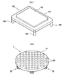
- Fig. 1 is a perspective view of a conventional exercise step.
- the conventional exercise step 100 includes a rectangular panel 110, and four legs 130.
- the legs 130 are provided at four corners of the panel 110 under the panel 110, and are made of elastic materials.
- a foot contact plate 120 is provided at a top surface of the panel 110. Actually, a user's feet are in contact with the foot contact plate 120 of the panel 110.
- the exercise step 100 When one desires to exercise using the exercise step 100, the exercise step 100 having such a construction is placed on a flat surface, that is, a floor. Thereafter, a user repeatedly steps onto and off of the foot contact plate 120 of the panel 110. Or, the user jumps on the foot contact plate 120. At this time, a load of the user is transmitted from the foot contact plate 120 and the panel 110 through the legs 130 to the support surface.
- the legs 130 are elastically deformed to absorb a load applied to the panel 110, thus preventing a shock from being transmitted to the user's knees. That is, such an exercise step 100 prevents a user's knees from being injured, when the user repeatedly steps onto and off of the foot contact plate 120 or jumps on the foot contact plate 120 of the exercise step 100.
- the conventional exercise step 100 has a problem that only the legs 130 are made of a cushioning material, such as polyurethane, so a cushioning capacity of the exercise step 100 is insufficient to prevent a shock from being transmitted to a user's knees. Thus, the conventional exercise step 100 does not sufficiently prevent a shock from being transmitted to a user's knees and allow the user to exercise safely and comfortably.
- a cushioning capacity of the exercise step 100 is insufficient to prevent a shock from being transmitted to a user's knees.
- the conventional exercise step 100 does not sufficiently prevent a shock from being transmitted to a user's knees and allow the user to exercise safely and comfortably.
- the conventional exercise step 100 has another problem that only the legs 130 have a cushioning capacity, so the foot contact plate 120 and the panel 110 may be undesirably deformed when the exercise step 100 is used for a lengthy period of time.
- the conventional exercise step 100 has a further problem that the cushioning capacity of the legs 130 is not controlled, so a different exercise step must be purchased according to a user's weight.
- US Patent 5,441,466 discloses an exercise step that includes a generally rectangular stepping platform having first and second ends and further includes first and second pairs of leg bellows respectively mounted to the first and second ends of the platform thereby forming four legs for supporting the stepping platform above a supporting surface.
- Each pair of leg bellows is controlled by a single valve for selectively simultaneously inflating or deflating the pair of leg bellows to selectively adjust the height of the platform above a supporting surface.
- this exercise step provides insufficient cushioning capacity.
- UK Patent Application GB 2 131 517 A discloses a shock absorber, more specially for use in office machines, is made up of a housing with two oppositely placed, rigid end plates joined together by a bellows-like casing, one of the end plates having a port running into the space inside the casing and having a choke valve fitted therein.
- the choke is adjustable and preferably has a check valve function.
- this patent does not disclose an exercise step.
- an object of the present invention is to provide an exercise step with air-cushioning legs, which has an excellent air cushioning effect, thus protecting a user's knees from injury and allowing the user to exercise in comfort and safety.
- Another object of the present invention is to provide an exercise step with air-cushioning legs, which is designed to minimize noise generated during a cushioning operation and have an excellent cushioning effect.
- a further object of the present invention is to provide an exercise step with air-cushioning legs, which is designed to prevent a panel from being undesirably deformed due to a user's load.
- the present invention provides an exercise step, including a plate-shaped panel, and an air-cushioning leg provided under the panel to support the panel and absorbing a load applied to the panel by an air cushioning effect.
- an air-cushioning leg includes a main body having a double- or more-layered structure and an air control unit functioning to discharge a part of cushioning air from the main body to the outside, when a load is applied to the panel.
- an air-cushioning leg includes a main body having a plurality of tubular bulged parts having different capacities, the bulged parts arranged to form a layered structure, a closed base part coming into contact with a support surface, and an upper end partially opened to define an air passage, an air control unit seated in the open part of the upper end to control an amount of air which flows in and out the main body, and a cover member covering the upper end of the main body in which the air control unit is seated.
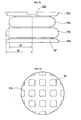
- FIG. 2 is a perspective view of an exercise step according to a primary embodiment of the present invention.
- an exercise step 1 according to the primary embodiment of the present invention includes a plateshaped panel 10 and four air-cushioning legs 30.
- the air-cushioning legs 30 are mounted to four corners of the panel 10 under the panel 10.
- a plurality of embossments 20 are formed on a top surface of the panel 10.
- the embossments 20 prevent a user from slipping and falling on the panel 10 during an exercise, in addition to functioning to massaging the sole of the user's foot.
- the embossments 20 may be separately manufactured and mounted to the top surface of the panel 10.
- the embossments 20 are integrated with the panel 10 to form a single structure.
- the panel 10 is a kind of laminated compressed wood, and is fabricated by processing multi-layered sheets to which a synthetic resin is added, under high temperature and high pressure. When the panel 10 is manufactured in this way, the panel 10 is somewhat hard, and has excellent elasticity and elastic strain, so the panel 10 is not easily damaged or deformed.
- a plurality of air-cushioning legs 30 are provided at four corners of the panel 10 under the panel 10 to absorb the load applied to the panel 10.
- the air-cushioning legs 30 may be glued to the panel 10 under the panel 10.
- the air-cushioning legs 30 may be screwed to the panel 10 under the panel 10.
- each of the air-cushioning legs 30 includes a main body 31, an air control unit 35, and a cover member 34.
- the main body 31 has a plurality of tubular bulged parts 31b and 31c which have different capacities and are arranged to form a layered structure.
- the main body 31 also has a base part 31a and an upper end 31d.
- the base part 31a is closed and comes into contact with a support surface.
- the upper end 31d is partially opened to define an air passage.
- the air control unit 35 is seated in an open part 33 of the upper end 31d to control an amount of air which flows in and out the main body 31.
- the cover member 34 covers the upper end 31d of the main body 31 in which the air control unit 35 is seated.
- the open part 33 of the upper end 31d of the main body 31 includes a central opening 33a, and a plurality of radial slits 33b.
- the central opening 33a is formed at the center of the upper end 31d of the main body 31.
- the radial slits 33b are provided along the circumference of the upper end 31 d of the main body 31 at predetermined intervals in such a way as to communicate with the central opening 33a.
- a single radial slit may be formed, but it is preferable that a plurality of radial slits are formed, like the primary embodiment of the present invention.
- the air control unit 35 which is made of a porous material, such as a sponge, is seated in the open part 33.
- the air control unit 35 includes a control body 35a, and a plurality of flanges 35b.
- the control body 35a is seated in the central opening 33a.
- the flanges 35b outwardly extend from the control body 35a in a radial direction to be seated in the radial slits 33b.
- an air control unit 35' may have a shape different from the air control unit 35 of Fig. 5a . That is, a plurality of through holes 35c are provided in the control body 35a to additionally control the amount of air which flows in and out the main body 31. In this case, the shape and number of the through holes 35c may be changed.
- the air control unit 35' having a plurality of the through holes 35c in the control body 35a as shown in Fig. 5b has a higher cushioning effect in comparison with the air control unit 35 of Fig. 5a .
- the air-cushioning leg 30 equipped with the air control unit 35 of Fig. 5a is suitable for heavy adults
- the air-cushioning leg 30 equipped with the air control unit 35' of Fig. 5b is suitable for light adults and children.
- the bulged parts 31b and 31c comprise a first bulged part 31b and a second bulged part 31c.
- the first bulged part 31b is provided adjacent to the base part 31a of the main body 31.
- the second bulged part 31c is placed on the first bulged part 31b to form a layered structure.
- the radius R1 of the first bulged part 31b is larger than the radius R2 of the second bulged part 31c to maintain a high cushioning effect and stability. Further, it is preferable that junctions between the base part 31 a, the first and second bulged parts 31b and 31c, and the upper end 31d are constricted and inwardly rounded (see, "A"), thus allowing the main body 31 to be smoothly compressed.
- the radius R1 of the first bulged part 31b, the radius R2 of the second bulged part 31c, and the capacities of the first and second bulged parts 31b and 31c must be properly determined according to the size of the panel 10 and the magnitude of the load, but such variations are not described herein in detail.
- a plurality of foot parts 32 are projected from a bottom surface of the base part 31a of the main body 31, thus preventing the base part 31a of the main body 31 from being compressed due to the load.
- the foot parts 32 each have a rectangular block shape.
- the foot parts 32 may have a different shape without being limited to the rectangular block shape.
- the exercise step 1 is placed on a flat surface, that is, a floor.
- a user repeatedly steps onto and off of the panel 10 or jumps on the panel 10
- the load applied to the panel 10 is transmitted to the support surface through the panel 10 and the air-cushioning legs 30.
- the load applied to the panel 10 is absorbed by the panel 10 to some extent, but the load is mostly absorbed by the air-cushioning legs 30. That is, when the user compresses the panel 10, air is discharged from the main body 31 through the control body 35a seated in the central opening 33a and the flanges 35b seated in the radial slits 33b to the outside. Simultaneously, the second bulged part 31c is downwardly compressed toward the first bulged part 31b, thus absorbing the load applied to the panel 10.
- each of the air-cushioning legs 30 is provided with the air control unit 35 which is made of a porous material, thus preventing noise from being generated even when air is discharged from the main body 31 to the outside, therefore allowing a user to enjoy exercising in comfort and safety.
- the air-cushioning leg 30 equipped with the air control unit 35 of Fig. 5a is suitable for heavy adults, whereas the air-cushioning leg 30 equipped with the air control unit 35' of Fig. 5b is suitable for light adults and children.
- the exercise step 1 equipped with the air-cushioning legs 30 minimize noise generated during a cushioning operation, and has an excellent cushioning effect, thus protecting a user's knees from injury and allowing the user to exercise in comfort and safety.
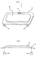
- an exercise step 1 includes a rectangular plate-shaped panel 10 and a plurality of air-cushioning legs 30.
- the air-cushioning legs 30 are mounted to four corners of the panel 10 under the panel 10.
- a rectangular foot contact plate 20 is provided on a top surface of the panel 10.
- the foot contact plate 20 is made of an elastic material, such as rubber, thus giving comfort to a user and having some cushioning effect.
- the panel 10 is a kind of laminated compressed wood, and is fabricated by processing multi-layered sheets to which a synthetic resin is added, under high temperature and high pressure. Thus, the panel 10 is somewhat hard, and has excellent elasticity and elastic strain, so the panel 10 is not easily damaged or deformed.
- a display unit 14 is provided at a predetermined portion of the panel 10.
- the display unit 14 is connected to a control unit (not shown), and displays at least one of the number of steps and a time. Thus, a user may set the number of steps and a time as desired when exercising.
- a plurality of bolts 10a are provided at four corners of the panel 10 under the panel 10.
- Each air-cushioning leg 30 is provided with a bolt receiving part 30a so that the bolt 10a is tightened into the bolt receiving part 30a (see, Fig. 8a ). That is, by tightening the bolts 10a of the panel 10 into the bolt receiving parts 30a of the air-cushioning legs 30, the air-cushioning legs 30 are easily mounted to the panel 10.
- the positions of the bolts 10a and the bolt receiving parts 30a may be changed. That is, the bolts 10a may be provided on the air-cushioning legs 30, while the bolt receiving parts 30a may be provided on the bottom surface of the panel 10.
- the air-cushioning legs 30 are provided under the panel 10 to support it, and absorb the load applied to the panel 10.
- Each of the air-cushioning legs 30 includes a main body 40 and an air control unit 50.
- the main body 40 is made of a material, such as polyurethane.
- the air control unit 50 functions to discharge a part of cushioning air from the main body 40 to the outside, when the load is applied to the panel 10.
- the main body 40 may have a two-layered structure having two bulged parts or a multi-layered structure having four or more bulged parts. However, the main body 40 has three bulged parts 40a, 40b, and 40c, which are layered in a vertical direction.
- the air control unit 50 includes a cover part 51 and a control part 52.
- the cover part 51 covers an open part of the main body 40. Air flow holes 51 a and 51 b of different sizes are formed in the cover part 51.
- the control part 52 is rotatably mounted to the cover part 51 to selectively open or close the air flow holes 51a and 51b.
- the control part 52 is provided with a handle 52a.
- the exercise step 1 of the control part 52 When a heavy adult uses the exercise step 1 of the control part 52 is rotated to open a smaller air flow hole 51a. On the contrary, when a light child uses the exercise step 1 the control part 52 is rotated to open a larger air flow hole 51b.
- the exercise step 1 of the present invention allows a cushioning effect to be controlled according to the user's load.
- the exercise step 1 is placed on a flat surface, that is, a floor.
- a user repeatedly steps onto and off of the foot contact plate 20 of the panel 10 or jumps at a fixed position on the foot contact plate 20, the load applied to the panel 10 is transmitted to the support surface through the panel 10 and the air-cushioning legs 30.
- the load applied to the panel 10 is absorbed by the panel 10 and the foot contact plate 20 to some extent, but the load is mostly absorbed by the air-cushioning legs 30. That is, the load is primarily absorbed when the bulged parts 40a, 40b, and 40c of the main body 40 are compressed. Secondarily, the load is absorbed when air is discharged from the main body 40 through at least one of the air flow holes 51a and 51b to the outside.
- the exercise step 1 of the present invention allows an air-cushioning effect to be controlled according to the user's load.
- a cushioning operation is effectively carried out by the air-cushioning legs 30, thus reducing a shock transmitted to the user's knees, allowing the user to exercise in comfort and safety, and preventing the panel 10 from being deformed by the load. Further, the user may set and confirm a time and the number of steps during exercise.
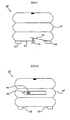
- a main body 40' of each air-cushioning leg 30' is designed such that two cover parts 42 and 43 are provided at an open lower part of the main body 40'.
- the two cover parts 42 and 43 partially overlap with each other to form an overlapping part.
- An adjusting bolt 44 is tightened into the overlapping part in such a way that the cover parts 42 and 43 are spaced apart from each other by a predetermined interval, thus controlling the amount of air which flows out of the main body 40'.
- an air flow opening 45 is provided at a side of a main body 40", and a sliding door 46 is mounted to the air flow opening 45 to control an opening ratio of the air flow opening 45.
- the main bodies 40' and 40" according to the embodiments of figures 9 and 10 also have foot parts 32 at the bottom surfaces of the main bodies 40' and 40".
- each air-cushioning leg may be designed to have a structure shown in Fig. 11b .
- the reference numerals designate components corresponding to those shown in Fig. 11a . The components similar to those shown in Fig. 11a are not described herein in detail.
- the air flow holes 151a and 252a are provided at the upper portions of the main bodies 140 and 240, respectively.
- air flow holes may be formed as shown in Fig. 11c , to accomplish the same effect as the air flow holes 151a and 252a of Figs. 11a and 11b . That is, according to the embodiment of Fig. 11c , a plurality of air flow holes 353a are provided in the bottom surface of a main body 340, and a sliding door 346 is provided to selectively open or close the air flow holes 353a, thus controlling an opening ratio of the air flow holes 353a. Further, foot parts 342 according to the embodiment of figure 11c are radially arranged on the bottom surface of the main body 340, differently from the above embodiments.
- each air-cushioning leg 30 includes the main body 40 and the air control unit 50.
- the main body 40 has a three-layered structure and is made of thermoplastic polyurethane having a relatively high elastic force, a sufficient cushioning effect is accomplished using only the main body 40 of each air-cushioning leg 30.
- the cushioning effect of the exercise step 1 is maximized.
- the panel 10 is made of a laminated compressed wood.
- the panel 10 may be made of wood having elasticity or other elastic materials.
- the panel 10 has a rectangular or circular shape, but the panel may have other shapes.
- the foot contact plate 20 is provided on the top surface of the panel 10. But, the panel 10 may not be provided with the foot contact plate 20.
- the present invention provides an exercise step, which has an excellent cushioning effect, thus preventing a shock from being transmitted to a user's knees and allowing the user to exercise in comfort and safety.
- the present invention provides an exercise step, which is capable of minimizing noise generated during a cushioning operation, and has an excellent cushioning effect.
- the exercise step of the present invention has a more excellent cushioning effect, in comparison with a conventional exercise step, thus preventing a panel from being deformed and thereby having a long lifespan.
- the present invention provides an exercise step, which is provided with a display unit, thus allowing a user to confirm the number of steps and a time during an exercise.
Landscapes
- Health & Medical Sciences (AREA)
- Orthopedic Medicine & Surgery (AREA)
- Rehabilitation Therapy (AREA)
- General Health & Medical Sciences (AREA)
- Physical Education & Sports Medicine (AREA)
- Mattresses And Other Support Structures For Chairs And Beds (AREA)
- Rehabilitation Tools (AREA)
- Vibration Prevention Devices (AREA)
- Professional, Industrial, Or Sporting Protective Garments (AREA)
Description
- The present invention relates, in general, to an exercise to with air-cushioning legs and more particularly, to an exercise step which is designed to have an excellent air cushioning effect, thus protecting a user's knees from injury and allowing the user to exercise in comfort and safety, and which is designed to minimize noise generated during a cushioning operation.
-
Fig. 1 is a perspective view of a conventional exercise step. As shown in the drawing, theconventional exercise step 100 includes arectangular panel 110, and fourlegs 130. Thelegs 130 are provided at four corners of thepanel 110 under thepanel 110, and are made of elastic materials. Afoot contact plate 120 is provided at a top surface of thepanel 110. Actually, a user's feet are in contact with thefoot contact plate 120 of thepanel 110. - When one desires to exercise using the
exercise step 100, theexercise step 100 having such a construction is placed on a flat surface, that is, a floor. Thereafter, a user repeatedly steps onto and off of thefoot contact plate 120 of thepanel 110. Or, the user jumps on thefoot contact plate 120. At this time, a load of the user is transmitted from thefoot contact plate 120 and thepanel 110 through thelegs 130 to the support surface. - In this case, the
legs 130 are elastically deformed to absorb a load applied to thepanel 110, thus preventing a shock from being transmitted to the user's knees. That is, such anexercise step 100 prevents a user's knees from being injured, when the user repeatedly steps onto and off of thefoot contact plate 120 or jumps on thefoot contact plate 120 of theexercise step 100. - However, the
conventional exercise step 100 has a problem that only thelegs 130 are made of a cushioning material, such as polyurethane, so a cushioning capacity of theexercise step 100 is insufficient to prevent a shock from being transmitted to a user's knees. Thus, theconventional exercise step 100 does not sufficiently prevent a shock from being transmitted to a user's knees and allow the user to exercise safely and comfortably. - Further, the
conventional exercise step 100 has another problem that only thelegs 130 have a cushioning capacity, so thefoot contact plate 120 and thepanel 110 may be undesirably deformed when theexercise step 100 is used for a lengthy period of time. Theconventional exercise step 100 has a further problem that the cushioning capacity of thelegs 130 is not controlled, so a different exercise step must be purchased according to a user's weight. -
US Patent 5,441,466 discloses an exercise step that includes a generally rectangular stepping platform having first and second ends and further includes first and second pairs of leg bellows respectively mounted to the first and second ends of the platform thereby forming four legs for supporting the stepping platform above a supporting surface. Each pair of leg bellows is controlled by a single valve for selectively simultaneously inflating or deflating the pair of leg bellows to selectively adjust the height of the platform above a supporting surface. However, as with theconventional exercise step 100, this exercise step provides insufficient cushioning capacity. - UK Patent Application
GB 2 131 517 A - Accordingly, the present invention as defined by claim 1 has been made keeping in mind the above problems occurring in the prior art, and an object of the present invention is to provide an exercise step with air-cushioning legs, which has an excellent air cushioning effect, thus protecting a user's knees from injury and allowing the user to exercise in comfort and safety.
- Another object of the present invention is to provide an exercise step with air-cushioning legs, which is designed to minimize noise generated during a cushioning operation and have an excellent cushioning effect.
- A further object of the present invention is to provide an exercise step with air-cushioning legs, which is designed to prevent a panel from being undesirably deformed due to a user's load.
- In order to accomplish the above object, the present invention provides an exercise step, including a plate-shaped panel, and an air-cushioning leg provided under the panel to support the panel and absorbing a load applied to the panel by an air cushioning effect.
- Further, in order to accomplish the above object, an air-cushioning leg includes a main body having a double- or more-layered structure and an air control unit functioning to discharge a part of cushioning air from the main body to the outside, when a load is applied to the panel.
- In order to accomplish the above object, an air-cushioning leg includes a main body having a plurality of tubular bulged parts having different capacities, the bulged parts arranged to form a layered structure, a closed base part coming into contact with a support surface, and an upper end partially opened to define an air passage, an air control unit seated in the open part of the upper end to control an amount of air which flows in and out the main body, and a cover member covering the upper end of the main body in which the air control unit is seated.
- The above and other objects, features and other advantages of the present invention will be more clearly understood from the following detailed description taken in conjunction with the accompanying drawings, in which:
-
Fig. 1 is a perspective view of a conventional exercise step; -
Fig. 2 is a perspective view of an exercise step according to a primary embodiment of the present invention; -
Fig. 3 is an exploded perspective view of an air-cushioning leg shown inFig. 2 ; -
Figs. 4a to 4c are a plan view, a side sectional view, and a bottom view of the air-cushioning leg shown inFig. 3 , respectively; -
Fig. 5a is a perspective view of an air control unit included in the air-cushioning leg of the primary embodiment of the present invention; -
Fig. 5b is a perspective view of an air control unit according to a modification of the primary embodiment of the present invention; -
Fig. 6 is a perspective view of an exercise step according to an embodiment useful for understanding the invention; -
Fig. 7 is a side sectional view showing a part of the exercise step shown inFig. 6 , in which air-cushioning legs are removed from a panel; -
Figs. 8a and 8b are perspective views of one of the air-cushioning legs included in the exercise step shown inFig. 6 , respectively; -
Fig. 9 is a side sectional view of an air-cushioning leg according to an embodiment useful for understanding the invention; -
Fig. 10 is a side sectional view of an air-cushioning leg according to an embodiment useful for understanding the invention; -
Figs. 11a and 11b are plan views of air-cushioning legs according to embodiments useful for understanding the invention; -
Fig. 11c is a bottom view of an air-cushioning leg according to an embodiment useful for understanding the invention; - Reference should now be made to the drawings, in which the same reference numerals are used throughout the different drawings to designate the same or similar components.
-
Fig. 2 is a perspective view of an exercise step according to a primary embodiment of the present invention. As shown in the drawing, an exercise step 1 according to the primary embodiment of the present invention includes aplateshaped panel 10 and four air-cushioning legs 30. The air-cushioning legs 30 are mounted to four corners of thepanel 10 under thepanel 10. - A plurality of
embossments 20 are formed on a top surface of thepanel 10. Theembossments 20 prevent a user from slipping and falling on thepanel 10 during an exercise, in addition to functioning to massaging the sole of the user's foot. Theembossments 20 may be separately manufactured and mounted to the top surface of thepanel 10. Preferably, theembossments 20 are integrated with thepanel 10 to form a single structure. - The
panel 10 is a kind of laminated compressed wood, and is fabricated by processing multi-layered sheets to which a synthetic resin is added, under high temperature and high pressure. When thepanel 10 is manufactured in this way, thepanel 10 is somewhat hard, and has excellent elasticity and elastic strain, so thepanel 10 is not easily damaged or deformed. - A plurality of air-
cushioning legs 30 are provided at four corners of thepanel 10 under thepanel 10 to absorb the load applied to thepanel 10. The air-cushioning legs 30 may be glued to thepanel 10 under thepanel 10. Alternatively, the air-cushioning legs 30 may be screwed to thepanel 10 under thepanel 10. - As shown in
Figs. 3 and4a to 4c , each of the air-cushioning legs 30 includes amain body 31, anair control unit 35, and acover member 34. Themain body 31 has a plurality of tubular bulgedparts main body 31 also has abase part 31a and anupper end 31d. Thebase part 31a is closed and comes into contact with a support surface. Theupper end 31d is partially opened to define an air passage. Theair control unit 35 is seated in anopen part 33 of theupper end 31d to control an amount of air which flows in and out themain body 31. Thecover member 34 covers theupper end 31d of themain body 31 in which theair control unit 35 is seated. - As shown in
Fig. 4a , theopen part 33 of theupper end 31d of themain body 31 includes acentral opening 33a, and a plurality ofradial slits 33b. Thecentral opening 33a is formed at the center of theupper end 31d of themain body 31. The radial slits 33b are provided along the circumference of theupper end 31 d of themain body 31 at predetermined intervals in such a way as to communicate with thecentral opening 33a. A single radial slit may be formed, but it is preferable that a plurality of radial slits are formed, like the primary embodiment of the present invention. - That is, when a user steps onto or jumps on the
panel 10, air is discharged from themain body 31 through thecentral opening 33a and the radial slits 33b to the outside. Subsequently, the bulgedparts panel 10. - In the case where only the
open part 33 is formed at theupper end 31 d of themain body 31, air excessively easily flows in and out themain body 31, so the load applied to thepanel 10 is not effectively absorbed. Thus, according to the present invention, theair control unit 35, which is made of a porous material, such as a sponge, is seated in theopen part 33. - As shown in
Fig. 5a , theair control unit 35 includes acontrol body 35a, and a plurality offlanges 35b. Thecontrol body 35a is seated in thecentral opening 33a. Theflanges 35b outwardly extend from thecontrol body 35a in a radial direction to be seated in theradial slits 33b. - When a user steps onto or jumps on the
panel 10 after theair control unit 35 is seated in theopen part 33 of theupper end 31d of themain body 31, air is discharged from themain body 31 through thecontrol body 35a seated in thecentral opening 33a and theflanges 35b seated in the radial slits 33b to the outside. Simultaneously, the bulgedparts panel 10. According to the present invention, since theair control unit 35 is made of a porous material, noise is not generated even when air flows in and out themain body 31, thus allowing a user to exercise in comfort and safety. - Meanwhile, as shown in
Fig. 5b , an air control unit 35' may have a shape different from theair control unit 35 ofFig. 5a . That is, a plurality of throughholes 35c are provided in thecontrol body 35a to additionally control the amount of air which flows in and out themain body 31. In this case, the shape and number of the throughholes 35c may be changed. - The air control unit 35' having a plurality of the through
holes 35c in thecontrol body 35a as shown inFig. 5b , has a higher cushioning effect in comparison with theair control unit 35 ofFig. 5a . Thus, the air-cushioningleg 30 equipped with theair control unit 35 ofFig. 5a is suitable for heavy adults, whereas the air-cushioningleg 30 equipped with the air control unit 35' ofFig. 5b is suitable for light adults and children. - As shown in
Fig. 4b , the bulgedparts part 31b and a second bulgedpart 31c. The first bulgedpart 31b is provided adjacent to thebase part 31a of themain body 31. The second bulgedpart 31c is placed on the first bulgedpart 31b to form a layered structure. - As shown in
Fig. 4b , it is preferable that the radius R1 of the first bulgedpart 31b is larger than the radius R2 of the second bulgedpart 31c to maintain a high cushioning effect and stability. Further, it is preferable that junctions between thebase part 31 a, the first and second bulgedparts upper end 31d are constricted and inwardly rounded (see, "A"), thus allowing themain body 31 to be smoothly compressed. Of course, the radius R1 of the first bulgedpart 31b, the radius R2 of the second bulgedpart 31c, and the capacities of the first and second bulgedparts panel 10 and the magnitude of the load, but such variations are not described herein in detail. - As shown in
Fig. 4c , a plurality offoot parts 32 are projected from a bottom surface of thebase part 31a of themain body 31, thus preventing thebase part 31a of themain body 31 from being compressed due to the load. According to the primary embodiment of the present invention, thefoot parts 32 each have a rectangular block shape. However, thefoot parts 32 may have a different shape without being limited to the rectangular block shape. - The use of the exercise step 1 constructed in this way will be described in the following.
- First, the exercise step 1 is placed on a flat surface, that is, a floor. Next, when a user repeatedly steps onto and off of the
panel 10 or jumps on thepanel 10, the load applied to thepanel 10 is transmitted to the support surface through thepanel 10 and the air-cushioning legs 30. - At this time, the load applied to the
panel 10 is absorbed by thepanel 10 to some extent, but the load is mostly absorbed by the air-cushioning legs 30. That is, when the user compresses thepanel 10, air is discharged from themain body 31 through thecontrol body 35a seated in thecentral opening 33a and theflanges 35b seated in the radial slits 33b to the outside. Simultaneously, the second bulgedpart 31c is downwardly compressed toward the first bulgedpart 31b, thus absorbing the load applied to thepanel 10. - In this case, each of the air-
cushioning legs 30 is provided with theair control unit 35 which is made of a porous material, thus preventing noise from being generated even when air is discharged from themain body 31 to the outside, therefore allowing a user to enjoy exercising in comfort and safety. - Of course, as described above, the air-cushioning
leg 30 equipped with theair control unit 35 ofFig. 5a is suitable for heavy adults, whereas the air-cushioningleg 30 equipped with the air control unit 35' ofFig. 5b is suitable for light adults and children. - As such, the exercise step 1 equipped with the air-
cushioning legs 30 minimize noise generated during a cushioning operation, and has an excellent cushioning effect, thus protecting a user's knees from injury and allowing the user to exercise in comfort and safety. - As shown in
Fig. 6 , an exercise step 1 includes a rectangular plate-shapedpanel 10 and a plurality of air-cushioning legs 30. The air-cushioning legs 30 are mounted to four corners of thepanel 10 under thepanel 10. A rectangularfoot contact plate 20 is provided on a top surface of thepanel 10. Thefoot contact plate 20 is made of an elastic material, such as rubber, thus giving comfort to a user and having some cushioning effect. - The
panel 10 is a kind of laminated compressed wood, and is fabricated by processing multi-layered sheets to which a synthetic resin is added, under high temperature and high pressure. Thus, thepanel 10 is somewhat hard, and has excellent elasticity and elastic strain, so thepanel 10 is not easily damaged or deformed. - A
display unit 14 is provided at a predetermined portion of thepanel 10. Thedisplay unit 14 is connected to a control unit (not shown), and displays at least one of the number of steps and a time. Thus, a user may set the number of steps and a time as desired when exercising. - As shown in
Fig. 7 , a plurality ofbolts 10a are provided at four corners of thepanel 10 under thepanel 10. Each air-cushioningleg 30 is provided with abolt receiving part 30a so that thebolt 10a is tightened into thebolt receiving part 30a (see,Fig. 8a ). That is, by tightening thebolts 10a of thepanel 10 into thebolt receiving parts 30a of the air-cushioning legs 30, the air-cushioning legs 30 are easily mounted to thepanel 10. - Although not shown in the drawings, the positions of the
bolts 10a and thebolt receiving parts 30a may be changed. That is, thebolts 10a may be provided on the air-cushioning legs 30, while thebolt receiving parts 30a may be provided on the bottom surface of thepanel 10. - The air-
cushioning legs 30 are provided under thepanel 10 to support it, and absorb the load applied to thepanel 10. Each of the air-cushioning legs 30 includes amain body 40 and anair control unit 50. Themain body 40 is made of a material, such as polyurethane. Theair control unit 50 functions to discharge a part of cushioning air from themain body 40 to the outside, when the load is applied to thepanel 10. - The
main body 40 may have a two-layered structure having two bulged parts or a multi-layered structure having four or more bulged parts. However, themain body 40 has three bulgedparts - As shown in
Fig. 8b , theair control unit 50 includes acover part 51 and acontrol part 52. Thecover part 51 covers an open part of themain body 40. Air flow holes 51 a and 51 b of different sizes are formed in thecover part 51. Thecontrol part 52 is rotatably mounted to thecover part 51 to selectively open or close the air flow holes 51a and 51b. Preferably, thecontrol part 52 is provided with ahandle 52a. - When a heavy adult uses the exercise step 1 of the
control part 52 is rotated to open a smaller air flow hole 51a. On the contrary, when a light child uses the exercise step 1 thecontrol part 52 is rotated to open a largerair flow hole 51b. Thus, the exercise step 1 of the present invention allows a cushioning effect to be controlled according to the user's load. - The use of the exercise step 1 according to the embodiment of
figures 6, 7 ,8a and 8b will be described in the following. - First, the exercise step 1 is placed on a flat surface, that is, a floor. Next, when a user repeatedly steps onto and off of the
foot contact plate 20 of thepanel 10 or jumps at a fixed position on thefoot contact plate 20, the load applied to thepanel 10 is transmitted to the support surface through thepanel 10 and the air-cushioning legs 30. - At this time, the load applied to the
panel 10 is absorbed by thepanel 10 and thefoot contact plate 20 to some extent, but the load is mostly absorbed by the air-cushioning legs 30. That is, the load is primarily absorbed when the bulgedparts main body 40 are compressed. Secondarily, the load is absorbed when air is discharged from themain body 40 through at least one of the air flow holes 51a and 51b to the outside. - When a heavy adult uses the exercise step 1, the
control part 52 is rotated to open a smaller air flow hole 51a. Meanwhile, when a light child uses the exercise step 1, thecontrol part 52 is rotated to open a largerair flow hole 51b. Thus, the exercise step 1 of the present invention allows an air-cushioning effect to be controlled according to the user's load. - In the exercise step 1 according to the embodiment of
figures 6, 7 ,8a and 8b , a cushioning operation is effectively carried out by the air-cushioning legs 30, thus reducing a shock transmitted to the user's knees, allowing the user to exercise in comfort and safety, and preventing thepanel 10 from being deformed by the load. Further, the user may set and confirm a time and the number of steps during exercise. - Further, it is not necessary to provide the
air control unit 50 shown inFig. 8b . - According to an embodiment shown in
Fig. 9 , a main body 40' of each air-cushioning leg 30' is designed such that twocover parts cover parts bolt 44 is tightened into the overlapping part in such a way that thecover parts - According to an embodiment shown in
Fig. 10 , an air flow opening 45 is provided at a side of amain body 40", and a slidingdoor 46 is mounted to the air flow opening 45 to control an opening ratio of theair flow opening 45. Themain bodies 40' and 40" according to the embodiments offigures 9 and 10 also havefoot parts 32 at the bottom surfaces of themain bodies 40' and 40". - Although not shown in the drawings, several through holes having a predetermined size may be provided in a side of the
main body 40 to accomplish a higher cushioning effect. - Further, according to an embodiment shown in
Fig. 11a , a plurality ofair flow holes 151a are bored through acover part 151 which is provided at the upper portion of themain body 140. When acontrol part 152 is rotated, one or moreair flow holes 151a are opened. Alternatively, the main body of each air-cushioning leg may be designed to have a structure shown inFig. 11b . InFig. 11b , the reference numerals designate components corresponding to those shown inFig. 11a . The components similar to those shown inFig. 11a are not described herein in detail. - According to the embodiments of
Fig. 11a and 11b , theair flow holes main bodies Fig. 11c , to accomplish the same effect as theair flow holes Figs. 11a and 11b . That is, according to the embodiment ofFig. 11c , a plurality ofair flow holes 353a are provided in the bottom surface of amain body 340, and a slidingdoor 346 is provided to selectively open or close theair flow holes 353a, thus controlling an opening ratio of theair flow holes 353a. Further,foot parts 342 according to the embodiment offigure 11c are radially arranged on the bottom surface of themain body 340, differently from the above embodiments. - According to the above-mentioned embodiments of the present invention, each air-cushioning
leg 30 includes themain body 40 and theair control unit 50. In this case, since themain body 40 has a three-layered structure and is made of thermoplastic polyurethane having a relatively high elastic force, a sufficient cushioning effect is accomplished using only themain body 40 of each air-cushioningleg 30. However, when each air-cushioningleg 30 includes theair control unit 50 as well as themain body 40, the cushioning effect of the exercise step 1 is maximized. - According to the above-mentioned embodiments, the
panel 10 is made of a laminated compressed wood. However, thepanel 10 may be made of wood having elasticity or other elastic materials. Further, thepanel 10 has a rectangular or circular shape, but the panel may have other shapes. - According to the above-mentioned embodiments, the
foot contact plate 20 is provided on the top surface of thepanel 10. But, thepanel 10 may not be provided with thefoot contact plate 20. - As described above, the present invention provides an exercise step, which has an excellent cushioning effect, thus preventing a shock from being transmitted to a user's knees and allowing the user to exercise in comfort and safety.
- Further, the present invention provides an exercise step, which is capable of minimizing noise generated during a cushioning operation, and has an excellent cushioning effect. The exercise step of the present invention has a more excellent cushioning effect, in comparison with a conventional exercise step, thus preventing a panel from being deformed and thereby having a long lifespan.
- The present invention provides an exercise step, which is provided with a display unit, thus allowing a user to confirm the number of steps and a time during an exercise.
- Although the preferred embodiments of the present invention have been disclosed for illustrative purposes, those skilled in the art will appreciate that various modifications, additions and substitutions are possible, without departing from the scope of the invention as disclosed in the accompanying claims.
Claims (11)
- An exercise step (1), comprising:a plate-shaped panel (10); anda plurality of air-cushioning legs (30) provided under the panel (10) to support the panel (10), and absorb a load applied to the panel (10) by an air cushioning effect, characterized in that each air-cushioning leg of said plurality of air-cushioning legs (30) comprises:a main body (31), including:a plurality of tubular bulged parts (31b, 31c) having different capacities, said bulged parts (31b, 31c) being arranged to form a layered structure;a closed base part (31a) coming into contact with a support surface; andan upper end (31d) partially opened to define an air passage;an air control unit (35, 35') seated in the open part (33) of the upper end (31d) to control an amount of air which flows into and out of the main body (31); anda cover member (34) covering the upper end (31d) of the main body (31) in which the air control unit (35, 35') is seated.
- The exercise step (1) according to claim 1, wherein said open part (33) of the upper end (31d) of the main body (31) comprises:a central opening (33a) formed at a center of the upper end (31d) of the main body (31); anda plurality of radial slits (33b) provided along a circumference of the upper end (31d) of the main body (31) at predetermined intervals, and communicating with the central opening (33a).
- The exercise step (1) according to claim 2, wherein said air control unit (35, 35') comprises:a control body (35a) seated in the central opening (33a); anda plurality of flanges (35b) outwardly extending from the control body (35a) in a radial direction to be seated in the radial slits (33b), whereby said air control unit (35, 35') controls the amount of air which flows in and out of the main body.
- The exercise step (1) according to claim 3, wherein at least one through hole (35c) is provided in the control body (35a) to additionally control the amount of air which flows in and out of the main body (31).
- The exercise step (1) according to any one of claims 1 to 4, wherein said air control unit (35, 35') is made of a porous material.
- The exercise step (1) according to claim 1, wherein said bulged parts comprise:a fist bulged part (31b) provided adjacent to the base part (31a) of the main body (31); anda second bulged part (31c) placed on the first bulged part (31b) to form a layered structure, said second bulged part (31b) being smaller in diameter than the first bulged art (31a).
- The exercise step (1) according to claim 1, wherein a plurality of foot parts (32) are projected from a bottom surface of the base part (31a) of the main body (31), thus preventing the base part (31a) of the main body (31) from being compressed due to the load.
- The exercise step (1) according to claim 1, wherein said air-cushioning legs (30) comprises:a main body (40) having a two or more layered structure; andan air control unit (50) functioning to discharge a part of cushioning air from the main body (40) to an outside.
- The exercise step (1) according to claim 8, wherein three or more air-cushioning legs (30) are provided under the panel (10) to support the panel (10), and
said main body (40) comprises three bulged parts (40a, 40b, 40c), said three bulged parts (40a, 40b, 40c) being layered in a vertical direction. - The exercise step (1) according to claim 8, wherein said air control unit (50) comprises:a cover part (51) covering the open part of the main body (40), with air flow holes (51a, 51b) of different sizes being formed in the cover part (51); anda control part (52) rotatably mounted to the cover part (51) to control an opening ratio of the air flow holes (51a, 51b).
- The exercise step (1) according to claim 10, wherein said control part (52) is provided with a handle (52a).
Applications Claiming Priority (7)
| Application Number | Priority Date | Filing Date | Title |
|---|---|---|---|
| KR2020010033045U KR200265396Y1 (en) | 2001-06-23 | 2001-10-29 | Health air step |
| KR2001033045U | 2001-10-29 | ||
| KR2002008484 | 2002-02-18 | ||
| KR10-2002-0008484A KR100446588B1 (en) | 2002-02-18 | 2002-02-18 | Exercising air footboard and buffer member for air footboard |
| KR2002029872U | 2002-10-07 | ||
| KR2020020029872U KR200298847Y1 (en) | 2002-10-07 | 2002-10-07 | Exercising air footboard |
| PCT/KR2002/001979 WO2003037445A1 (en) | 2001-10-29 | 2002-10-23 | Exercising air footboard and buffer for air footboard |
Publications (3)
| Publication Number | Publication Date |
|---|---|
| EP1455903A1 EP1455903A1 (en) | 2004-09-15 |
| EP1455903A4 EP1455903A4 (en) | 2008-06-25 |
| EP1455903B1 true EP1455903B1 (en) | 2013-10-02 |
Family
ID=27350476
Family Applications (1)
| Application Number | Title | Priority Date | Filing Date |
|---|---|---|---|
| EP02781974.7A Expired - Lifetime EP1455903B1 (en) | 2001-10-29 | 2002-10-23 | Exercising air footboard |
Country Status (5)
| Country | Link |
|---|---|
| US (3) | US7160229B2 (en) |
| EP (1) | EP1455903B1 (en) |
| JP (1) | JP4169695B2 (en) |
| DE (1) | DE20221820U1 (en) |
| WO (1) | WO2003037445A1 (en) |
Cited By (1)
| Publication number | Priority date | Publication date | Assignee | Title |
|---|---|---|---|---|
| CN107899175A (en) * | 2017-10-27 | 2018-04-13 | 潘巍巍 | It is a kind of safety bounce bed |
Families Citing this family (21)
| Publication number | Priority date | Publication date | Assignee | Title |
|---|---|---|---|---|
| US20080132384A1 (en) * | 2000-08-14 | 2008-06-05 | Publicover Mark W | Exercise system |
| EP1455903B1 (en) * | 2001-10-29 | 2013-10-02 | Equbic Product Company, LLC | Exercising air footboard |
| US20070197355A1 (en) * | 2006-02-22 | 2007-08-23 | Brown & Company Of Pensacola, Inc. | Aero hydraulic exercise and physical therapy equipment and method |
| US7780583B2 (en) * | 2006-02-22 | 2010-08-24 | Brown & Company Of Pensacola, Inc. | Aero hydraulic exercise and physical therapy equipment and method |
| KR100638520B1 (en) * | 2006-08-04 | 2006-10-26 | 정찬모 | A health air board |
| EP2107923A4 (en) * | 2007-01-16 | 2011-09-14 | Jong Seon Kim | Air step board for health |
| US8632440B2 (en) * | 2007-03-10 | 2014-01-21 | Istep Global, Llc | Proprioception training and exercise device |
| US8460161B2 (en) | 2007-03-10 | 2013-06-11 | Istep Global, Llc | Proprioception training and exercise apparatus |
| JP5591542B2 (en) * | 2007-03-10 | 2014-09-17 | アイステップ・グロウバル・リミテッド・ライアビリティ・カンパニー | Exercise equipment |
| US20100288901A1 (en) * | 2009-05-14 | 2010-11-18 | Wallach Mark S | Lateral tilt adapter for stationary exercise equipment |
| JP4532604B1 (en) * | 2010-02-26 | 2010-08-25 | 敬司 松野 | Slow step exercise platform |
| US8944979B2 (en) | 2010-10-12 | 2015-02-03 | B&R Plastics, Inc. | Exercise step using spirally shaped air-cushioning legs |
| USD739485S1 (en) * | 2011-09-23 | 2015-09-22 | B & R Plastics, Inc. | Support |
| US9011295B2 (en) | 2012-02-17 | 2015-04-21 | The Prophet Corporation | Aerobic step |
| US20140051553A1 (en) * | 2012-07-12 | 2014-02-20 | John Hetzel | Modular exercise platform |
| CN104001283B (en) * | 2014-06-10 | 2017-04-19 | 侯荣华 | High falling object receiving device |
| USD779000S1 (en) * | 2015-04-22 | 2017-02-14 | Jeffrey Olson | Balance board |
| US9731164B1 (en) * | 2016-02-02 | 2017-08-15 | Singularity Ltd. | Stationary bike comprising cylindrical elastic feet |
| USD798397S1 (en) * | 2016-02-29 | 2017-09-26 | Anel BELLEVUE | Exercise board |
| USD792532S1 (en) * | 2016-03-15 | 2017-07-18 | Jeff Olson | Stability platform board |
| CN110393887B (en) * | 2019-08-21 | 2024-04-16 | 温州优嘉游乐设备有限公司 | Trampoline |
Family Cites Families (39)
| Publication number | Priority date | Publication date | Assignee | Title |
|---|---|---|---|---|
| US3125377A (en) * | 1964-03-17 | Ottoman with changeable cushioning means therein | ||
| US3167312A (en) * | 1962-08-02 | 1965-01-26 | Roger M Blanchard | Trampoline type bouncer toy |
| US3162371A (en) * | 1963-12-20 | 1964-12-22 | Palmer Products Co | Manually operable air blower |
| US3263247A (en) * | 1964-03-03 | 1966-08-02 | Richard R Knittel | Headed hollow body support |
| US3332415A (en) * | 1964-04-30 | 1967-07-25 | Kendall & Co | Self-sealing pressure valve for inflatable splints and other devices |
| US3884463A (en) * | 1973-03-07 | 1975-05-20 | Roger J Malatesta | Pneumatic collapsible exercising device of the according type |
| US3821951A (en) * | 1973-05-09 | 1974-07-02 | Raymond Lee Organization Inc | Foot comfort producing apparatus |
| US4084811A (en) * | 1975-02-24 | 1978-04-18 | Han Cha Kyo | Hitting device for martial arts |
| US4204675A (en) * | 1978-08-02 | 1980-05-27 | Monicor Corp. | Air chamber leg exercising device |
| DE3244997A1 (en) | 1982-12-04 | 1984-06-14 | Festo-Maschinenfabrik Gottlieb Stoll, 7300 Esslingen | SHOCK ABSORBER |
| SE454742B (en) * | 1983-09-13 | 1988-05-30 | Gunilla Brennstam | DEVICE FOR THE EXERCISE OF A SINGLE PERSON'S LEG OR ARM MUSCLE |
| US4759543A (en) * | 1986-10-27 | 1988-07-26 | Feldman Susan M | Passive exercise cushion |
| JPH0790447B2 (en) | 1988-10-18 | 1995-10-04 | 株式会社牧野フライス製作所 | Tracer head detection error correction method |
| US5267923A (en) * | 1991-07-24 | 1993-12-07 | Gary Piaget | Reciprocating bellows operated exercise machine |
| US5544903A (en) * | 1991-10-11 | 1996-08-13 | Bears; James A. | Air bag toy |
| JPH0658964A (en) | 1992-04-22 | 1994-03-04 | Nec Corp | Intermodulation measuring apparatus for transmitter |
| US5186700A (en) * | 1992-08-27 | 1993-02-16 | Lee Wang Industry Ltd. | Pedaling exercise device |
| US5256118A (en) * | 1993-03-22 | 1993-10-26 | Far Great Plastics Ind. Co., Ltd. | Pedal exerciser |
| US5346444A (en) * | 1993-04-08 | 1994-09-13 | Hsieh Kuo C | Control valve for an exercise stair device |
| US5558398A (en) * | 1993-11-08 | 1996-09-24 | Santos; James P. | Self-adjusting seating system |
| US5441466A (en) * | 1994-02-03 | 1995-08-15 | Piaget; Gary | Exercise step with adjustable leg bellows |
| US5575738A (en) * | 1995-06-12 | 1996-11-19 | Hasbro, Inc. | Exercise and play apparatus |
| US5851166A (en) * | 1995-07-31 | 1998-12-22 | Bernardson; Peter S. | Lower extremity rehabilitation and toning exercise apparatus and method |
| US5813946A (en) * | 1995-10-12 | 1998-09-29 | Intex Recreation Corp. | Inflatable jumping toy and method |
| USD383813S (en) * | 1996-02-20 | 1997-09-16 | Zoller Robert G | Foot exercise device |
| US5626543A (en) * | 1996-04-03 | 1997-05-06 | Chen; Ping | Bellows-like exerciser |
| US5735780A (en) * | 1996-05-08 | 1998-04-07 | Genevieve M. Griffin | Chest and body exerciser |
| JP3260668B2 (en) | 1996-09-07 | 2002-02-25 | ヨン ソル パク | Shoe sole |
| KR19980028600U (en) * | 1996-11-23 | 1998-08-05 | 이결 | Double shock absorber of sports shoes |
| US6126152A (en) * | 1997-03-10 | 2000-10-03 | Synergy Services, Ltd. | Variable response pneumatic support |
| KR19990016108U (en) * | 1997-10-23 | 1999-05-15 | 김승호 | Treadmill |
| USD420413S (en) * | 1999-03-01 | 2000-02-08 | Gonzalez Richard J | Martial arts training device |
| US6024678A (en) * | 1999-03-08 | 2000-02-15 | Solomon; Guillermo | Vacuum cleaner leg exercise device |
| KR200255600Y1 (en) * | 1999-06-21 | 2001-12-24 | 채병연 | Air inflate type tumbling appliance |
| JP3511165B2 (en) * | 1999-07-30 | 2004-03-29 | 赤羽根工業株式会社 | Jumping board |
| ES2167202B1 (en) * | 2000-01-19 | 2003-04-16 | Cig Gestio I Assessorament Esp | DEVICE FOR THE ENTERTAINMENT OF AN EXTREMITY OF THE HUMAN BODY IN THE PRACTICE OF A SPECIFIC PHYSICAL ACTIVITY. |
| US6758795B2 (en) * | 2000-08-22 | 2004-07-06 | Stephen Barber | Adjustable water-fillable exercise weights |
| EP1455903B1 (en) * | 2001-10-29 | 2013-10-02 | Equbic Product Company, LLC | Exercising air footboard |
| CA2361111A1 (en) * | 2001-11-06 | 2003-05-06 | Cheng-Tzu Kuo | Foot stepper exercise machine |
-
2002
- 2002-10-23 EP EP02781974.7A patent/EP1455903B1/en not_active Expired - Lifetime
- 2002-10-23 JP JP2003539784A patent/JP4169695B2/en not_active Expired - Fee Related
- 2002-10-23 US US10/491,968 patent/US7160229B2/en not_active Expired - Lifetime
- 2002-10-23 DE DE20221820U patent/DE20221820U1/en not_active Expired - Lifetime
- 2002-10-23 WO PCT/KR2002/001979 patent/WO2003037445A1/en active Application Filing
-
2006
- 2006-11-22 US US11/603,248 patent/US8328699B2/en active Active
-
2009
- 2009-05-19 US US12/468,527 patent/US20090227427A1/en not_active Abandoned
Cited By (2)
| Publication number | Priority date | Publication date | Assignee | Title |
|---|---|---|---|---|
| CN107899175A (en) * | 2017-10-27 | 2018-04-13 | 潘巍巍 | It is a kind of safety bounce bed |
| CN107899175B (en) * | 2017-10-27 | 2019-06-18 | 潘巍巍 | It is a kind of safety bounce bed |
Also Published As
| Publication number | Publication date |
|---|---|
| US20090227427A1 (en) | 2009-09-10 |
| US7160229B2 (en) | 2007-01-09 |
| EP1455903A1 (en) | 2004-09-15 |
| EP1455903A4 (en) | 2008-06-25 |
| US20070155591A1 (en) | 2007-07-05 |
| WO2003037445A1 (en) | 2003-05-08 |
| US20050020408A1 (en) | 2005-01-27 |
| JP2005507291A (en) | 2005-03-17 |
| US8328699B2 (en) | 2012-12-11 |
| DE20221820U1 (en) | 2008-02-28 |
| JP4169695B2 (en) | 2008-10-22 |
Similar Documents
| Publication | Publication Date | Title |
|---|---|---|
| EP1455903B1 (en) | Exercising air footboard | |
| US7494446B2 (en) | Balancing device | |
| US5637057A (en) | Tire trampoline apparatus | |
| US5441466A (en) | Exercise step with adjustable leg bellows | |
| JP5591542B2 (en) | Exercise equipment | |
| US7406735B2 (en) | Air-inflated mattress | |
| US6575885B1 (en) | Inflatable device and method for using the device | |
| US5575738A (en) | Exercise and play apparatus | |
| WO2001024887A1 (en) | Inflatable device and method for using the device | |
| US5813946A (en) | Inflatable jumping toy and method | |
| US20080076638A1 (en) | Rebounder | |
| US20110160021A1 (en) | Exercise system | |
| KR100848353B1 (en) | A airboard for take exercise | |
| KR100446588B1 (en) | Exercising air footboard and buffer member for air footboard | |
| KR200298847Y1 (en) | Exercising air footboard | |
| KR200385431Y1 (en) | Exercising air footboard | |
| KR200312971Y1 (en) | Seesaw | |
| WO2008016202A1 (en) | A health air board | |
| KR200201053Y1 (en) | A jumping play utensil using a tire for a car | |
| KR200421118Y1 (en) | Buffer member for airfootboard | |
| WO2001034247A1 (en) | Play apparatus |
Legal Events
| Date | Code | Title | Description |
|---|---|---|---|
| PUAI | Public reference made under article 153(3) epc to a published international application that has entered the european phase |
Free format text: ORIGINAL CODE: 0009012 |
|
| 17P | Request for examination filed |
Effective date: 20040416 |
|
| AK | Designated contracting states |
Kind code of ref document: A1 Designated state(s): AT BE BG CH CY CZ DE DK EE ES FI FR GB GR IE IT LI LU MC NL PT SE SK TR |
|
| AX | Request for extension of the european patent |
Extension state: AL LT LV MK RO SI |
|
| RAP1 | Party data changed (applicant data changed or rights of an application transferred) |
Owner name: EQUBIC PRODUCT COMPANY, LLC |
|
| RIN1 | Information on inventor provided before grant (corrected) |
Inventor name: PARK, HEE-SUN |
|
| A4 | Supplementary search report drawn up and despatched |
Effective date: 20080528 |
|
| RIC1 | Information provided on ipc code assigned before grant |
Ipc: F16F 9/34 20060101ALI20080522BHEP Ipc: A63B 5/11 20060101AFI20030514BHEP Ipc: F16F 9/04 20060101ALI20080522BHEP Ipc: A63B 6/00 20060101ALI20080522BHEP |
|
| 17Q | First examination report despatched |
Effective date: 20100608 |
|
| GRAP | Despatch of communication of intention to grant a patent |
Free format text: ORIGINAL CODE: EPIDOSNIGR1 |
|
| INTG | Intention to grant announced |
Effective date: 20130423 |
|
| GRAS | Grant fee paid |
Free format text: ORIGINAL CODE: EPIDOSNIGR3 |
|
| GRAA | (expected) grant |
Free format text: ORIGINAL CODE: 0009210 |
|
| AK | Designated contracting states |
Kind code of ref document: B1 Designated state(s): AT BE BG CH CY CZ DE DK EE ES FI FR GB GR IE IT LI LU MC NL PT SE SK TR |
|
| REG | Reference to a national code |
Ref country code: GB Ref legal event code: FG4D |
|
| REG | Reference to a national code |
Ref country code: AT Ref legal event code: REF Ref document number: 634302 Country of ref document: AT Kind code of ref document: T Effective date: 20131015 Ref country code: CH Ref legal event code: EP |
|
| REG | Reference to a national code |
Ref country code: IE Ref legal event code: FG4D |
|
| REG | Reference to a national code |
Ref country code: DE Ref legal event code: R096 Ref document number: 60245611 Country of ref document: DE Effective date: 20131128 |
|
| REG | Reference to a national code |
Ref country code: AT Ref legal event code: MK05 Ref document number: 634302 Country of ref document: AT Kind code of ref document: T Effective date: 20131002 |
|
| REG | Reference to a national code |
Ref country code: NL Ref legal event code: VDEP Effective date: 20131002 |
|
| PG25 | Lapsed in a contracting state [announced via postgrant information from national office to epo] |
Ref country code: SE Free format text: LAPSE BECAUSE OF FAILURE TO SUBMIT A TRANSLATION OF THE DESCRIPTION OR TO PAY THE FEE WITHIN THE PRESCRIBED TIME-LIMIT Effective date: 20131002 Ref country code: NL Free format text: LAPSE BECAUSE OF FAILURE TO SUBMIT A TRANSLATION OF THE DESCRIPTION OR TO PAY THE FEE WITHIN THE PRESCRIBED TIME-LIMIT Effective date: 20131002 Ref country code: BE Free format text: LAPSE BECAUSE OF FAILURE TO SUBMIT A TRANSLATION OF THE DESCRIPTION OR TO PAY THE FEE WITHIN THE PRESCRIBED TIME-LIMIT Effective date: 20131002 Ref country code: CZ Free format text: LAPSE BECAUSE OF FAILURE TO SUBMIT A TRANSLATION OF THE DESCRIPTION OR TO PAY THE FEE WITHIN THE PRESCRIBED TIME-LIMIT Effective date: 20131002 Ref country code: FI Free format text: LAPSE BECAUSE OF FAILURE TO SUBMIT A TRANSLATION OF THE DESCRIPTION OR TO PAY THE FEE WITHIN THE PRESCRIBED TIME-LIMIT Effective date: 20131002 |
|
| PG25 | Lapsed in a contracting state [announced via postgrant information from national office to epo] |
Ref country code: CY Free format text: LAPSE BECAUSE OF FAILURE TO SUBMIT A TRANSLATION OF THE DESCRIPTION OR TO PAY THE FEE WITHIN THE PRESCRIBED TIME-LIMIT Effective date: 20131002 Ref country code: ES Free format text: LAPSE BECAUSE OF FAILURE TO SUBMIT A TRANSLATION OF THE DESCRIPTION OR TO PAY THE FEE WITHIN THE PRESCRIBED TIME-LIMIT Effective date: 20131002 Ref country code: AT Free format text: LAPSE BECAUSE OF FAILURE TO SUBMIT A TRANSLATION OF THE DESCRIPTION OR TO PAY THE FEE WITHIN THE PRESCRIBED TIME-LIMIT Effective date: 20131002 |
|
| REG | Reference to a national code |
Ref country code: CH Ref legal event code: PL |
|
| PG25 | Lapsed in a contracting state [announced via postgrant information from national office to epo] |
Ref country code: PT Free format text: LAPSE BECAUSE OF FAILURE TO SUBMIT A TRANSLATION OF THE DESCRIPTION OR TO PAY THE FEE WITHIN THE PRESCRIBED TIME-LIMIT Effective date: 20140203 |
|
| REG | Reference to a national code |
Ref country code: DE Ref legal event code: R097 Ref document number: 60245611 Country of ref document: DE |
|
| REG | Reference to a national code |
Ref country code: IE Ref legal event code: MM4A |
|
| PG25 | Lapsed in a contracting state [announced via postgrant information from national office to epo] |
Ref country code: MC Free format text: LAPSE BECAUSE OF FAILURE TO SUBMIT A TRANSLATION OF THE DESCRIPTION OR TO PAY THE FEE WITHIN THE PRESCRIBED TIME-LIMIT Effective date: 20131002 Ref country code: CH Free format text: LAPSE BECAUSE OF NON-PAYMENT OF DUE FEES Effective date: 20131031 Ref country code: LI Free format text: LAPSE BECAUSE OF NON-PAYMENT OF DUE FEES Effective date: 20131031 Ref country code: EE Free format text: LAPSE BECAUSE OF FAILURE TO SUBMIT A TRANSLATION OF THE DESCRIPTION OR TO PAY THE FEE WITHIN THE PRESCRIBED TIME-LIMIT Effective date: 20131002 |
|
| PLBE | No opposition filed within time limit |
Free format text: ORIGINAL CODE: 0009261 |
|
| STAA | Information on the status of an ep patent application or granted ep patent |
Free format text: STATUS: NO OPPOSITION FILED WITHIN TIME LIMIT |
|
| PG25 | Lapsed in a contracting state [announced via postgrant information from national office to epo] |
Ref country code: IT Free format text: LAPSE BECAUSE OF FAILURE TO SUBMIT A TRANSLATION OF THE DESCRIPTION OR TO PAY THE FEE WITHIN THE PRESCRIBED TIME-LIMIT Effective date: 20131002 Ref country code: SK Free format text: LAPSE BECAUSE OF FAILURE TO SUBMIT A TRANSLATION OF THE DESCRIPTION OR TO PAY THE FEE WITHIN THE PRESCRIBED TIME-LIMIT Effective date: 20131002 |
|
| 26N | No opposition filed |
Effective date: 20140703 |
|
| PG25 | Lapsed in a contracting state [announced via postgrant information from national office to epo] |
Ref country code: DK Free format text: LAPSE BECAUSE OF FAILURE TO SUBMIT A TRANSLATION OF THE DESCRIPTION OR TO PAY THE FEE WITHIN THE PRESCRIBED TIME-LIMIT Effective date: 20131002 |
|
| REG | Reference to a national code |
Ref country code: DE Ref legal event code: R097 Ref document number: 60245611 Country of ref document: DE Effective date: 20140703 |
|
| PG25 | Lapsed in a contracting state [announced via postgrant information from national office to epo] |
Ref country code: IE Free format text: LAPSE BECAUSE OF NON-PAYMENT OF DUE FEES Effective date: 20131023 |
|
| PGFP | Annual fee paid to national office [announced via postgrant information from national office to epo] |
Ref country code: GB Payment date: 20141118 Year of fee payment: 13 Ref country code: FR Payment date: 20141031 Year of fee payment: 13 Ref country code: DE Payment date: 20141113 Year of fee payment: 13 |
|
| REG | Reference to a national code |
Ref country code: DE Ref legal event code: R082 Ref document number: 60245611 Country of ref document: DE Representative=s name: PATENTANWAELTE LIPPERT, STACHOW & PARTNER, DE Ref country code: DE Ref legal event code: R082 Ref document number: 60245611 Country of ref document: DE Representative=s name: LIPPERT STACHOW PATENTANWAELTE RECHTSANWAELTE , DE |
|
| PG25 | Lapsed in a contracting state [announced via postgrant information from national office to epo] |
Ref country code: TR Free format text: LAPSE BECAUSE OF FAILURE TO SUBMIT A TRANSLATION OF THE DESCRIPTION OR TO PAY THE FEE WITHIN THE PRESCRIBED TIME-LIMIT Effective date: 20131002 |
|
| PG25 | Lapsed in a contracting state [announced via postgrant information from national office to epo] |
Ref country code: LU Free format text: LAPSE BECAUSE OF NON-PAYMENT OF DUE FEES Effective date: 20131023 Ref country code: BG Free format text: LAPSE BECAUSE OF FAILURE TO SUBMIT A TRANSLATION OF THE DESCRIPTION OR TO PAY THE FEE WITHIN THE PRESCRIBED TIME-LIMIT Effective date: 20131002 |
|
| PG25 | Lapsed in a contracting state [announced via postgrant information from national office to epo] |
Ref country code: GR Free format text: LAPSE BECAUSE OF NON-PAYMENT OF DUE FEES Effective date: 20131002 |
|
| REG | Reference to a national code |
Ref country code: DE Ref legal event code: R119 Ref document number: 60245611 Country of ref document: DE |
|
| GBPC | Gb: european patent ceased through non-payment of renewal fee |
Effective date: 20151023 |
|
| PG25 | Lapsed in a contracting state [announced via postgrant information from national office to epo] |
Ref country code: GR Free format text: LAPSE BECAUSE OF FAILURE TO SUBMIT A TRANSLATION OF THE DESCRIPTION OR TO PAY THE FEE WITHIN THE PRESCRIBED TIME-LIMIT Effective date: 20140103 |
|
| PG25 | Lapsed in a contracting state [announced via postgrant information from national office to epo] |
Ref country code: GB Free format text: LAPSE BECAUSE OF NON-PAYMENT OF DUE FEES Effective date: 20151023 Ref country code: DE Free format text: LAPSE BECAUSE OF NON-PAYMENT OF DUE FEES Effective date: 20160503 |
|
| REG | Reference to a national code |
Ref country code: FR Ref legal event code: ST Effective date: 20160630 |
|
| PG25 | Lapsed in a contracting state [announced via postgrant information from national office to epo] |
Ref country code: FR Free format text: LAPSE BECAUSE OF NON-PAYMENT OF DUE FEES Effective date: 20151102 |