EP1455402A1 - Fuel cell unit and operational state display control method - Google Patents
Fuel cell unit and operational state display control method Download PDFInfo
- Publication number
- EP1455402A1 EP1455402A1 EP04004527A EP04004527A EP1455402A1 EP 1455402 A1 EP1455402 A1 EP 1455402A1 EP 04004527 A EP04004527 A EP 04004527A EP 04004527 A EP04004527 A EP 04004527A EP 1455402 A1 EP1455402 A1 EP 1455402A1
- Authority
- EP
- European Patent Office
- Prior art keywords
- fuel cell
- cell unit
- fuel
- electronic apparatus
- user
- Prior art date
- Legal status (The legal status is an assumption and is not a legal conclusion. Google has not performed a legal analysis and makes no representation as to the accuracy of the status listed.)
- Granted
Links
Images


Classifications
-
- G—PHYSICS
- G06—COMPUTING OR CALCULATING; COUNTING
- G06F—ELECTRIC DIGITAL DATA PROCESSING
- G06F1/00—Details not covered by groups G06F3/00 - G06F13/00 and G06F21/00
- G06F1/16—Constructional details or arrangements
- G06F1/1613—Constructional details or arrangements for portable computers
- G06F1/1615—Constructional details or arrangements for portable computers with several enclosures having relative motions, each enclosure supporting at least one I/O or computing function
- G06F1/1616—Constructional details or arrangements for portable computers with several enclosures having relative motions, each enclosure supporting at least one I/O or computing function with folding flat displays, e.g. laptop computers or notebooks having a clamshell configuration, with body parts pivoting to an open position around an axis parallel to the plane they define in closed position
-
- G—PHYSICS
- G06—COMPUTING OR CALCULATING; COUNTING
- G06F—ELECTRIC DIGITAL DATA PROCESSING
- G06F1/00—Details not covered by groups G06F3/00 - G06F13/00 and G06F21/00
- G06F1/16—Constructional details or arrangements
- G06F1/1613—Constructional details or arrangements for portable computers
- G06F1/1633—Constructional details or arrangements of portable computers not specific to the type of enclosures covered by groups G06F1/1615 - G06F1/1626
- G06F1/1635—Details related to the integration of battery packs and other power supplies such as fuel cells or integrated AC adapter
-
- G—PHYSICS
- G06—COMPUTING OR CALCULATING; COUNTING
- G06F—ELECTRIC DIGITAL DATA PROCESSING
- G06F1/00—Details not covered by groups G06F3/00 - G06F13/00 and G06F21/00
- G06F1/16—Constructional details or arrangements
- G06F1/1613—Constructional details or arrangements for portable computers
- G06F1/1633—Constructional details or arrangements of portable computers not specific to the type of enclosures covered by groups G06F1/1615 - G06F1/1626
- G06F1/1684—Constructional details or arrangements related to integrated I/O peripherals not covered by groups G06F1/1635 - G06F1/1675
-
- G—PHYSICS
- G06—COMPUTING OR CALCULATING; COUNTING
- G06F—ELECTRIC DIGITAL DATA PROCESSING
- G06F1/00—Details not covered by groups G06F3/00 - G06F13/00 and G06F21/00
- G06F1/26—Power supply means, e.g. regulation thereof
-
- G—PHYSICS
- G06—COMPUTING OR CALCULATING; COUNTING
- G06F—ELECTRIC DIGITAL DATA PROCESSING
- G06F1/00—Details not covered by groups G06F3/00 - G06F13/00 and G06F21/00
- G06F1/26—Power supply means, e.g. regulation thereof
- G06F1/32—Means for saving power
- G06F1/3203—Power management, i.e. event-based initiation of a power-saving mode
-
- H—ELECTRICITY
- H01—ELECTRIC ELEMENTS
- H01M—PROCESSES OR MEANS, e.g. BATTERIES, FOR THE DIRECT CONVERSION OF CHEMICAL ENERGY INTO ELECTRICAL ENERGY
- H01M16/00—Structural combinations of different types of electrochemical generators
- H01M16/003—Structural combinations of different types of electrochemical generators of fuel cells with other electrochemical devices, e.g. capacitors, electrolysers
- H01M16/006—Structural combinations of different types of electrochemical generators of fuel cells with other electrochemical devices, e.g. capacitors, electrolysers of fuel cells with rechargeable batteries
-
- H—ELECTRICITY
- H01—ELECTRIC ELEMENTS
- H01M—PROCESSES OR MEANS, e.g. BATTERIES, FOR THE DIRECT CONVERSION OF CHEMICAL ENERGY INTO ELECTRICAL ENERGY
- H01M8/00—Fuel cells; Manufacture thereof
- H01M8/04—Auxiliary arrangements, e.g. for control of pressure or for circulation of fluids
- H01M8/04223—Auxiliary arrangements, e.g. for control of pressure or for circulation of fluids during start-up or shut-down; Depolarisation or activation, e.g. purging; Means for short-circuiting defective fuel cells
- H01M8/04225—Auxiliary arrangements, e.g. for control of pressure or for circulation of fluids during start-up or shut-down; Depolarisation or activation, e.g. purging; Means for short-circuiting defective fuel cells during start-up
-
- H—ELECTRICITY
- H01—ELECTRIC ELEMENTS
- H01M—PROCESSES OR MEANS, e.g. BATTERIES, FOR THE DIRECT CONVERSION OF CHEMICAL ENERGY INTO ELECTRICAL ENERGY
- H01M8/00—Fuel cells; Manufacture thereof
- H01M8/04—Auxiliary arrangements, e.g. for control of pressure or for circulation of fluids
- H01M8/04223—Auxiliary arrangements, e.g. for control of pressure or for circulation of fluids during start-up or shut-down; Depolarisation or activation, e.g. purging; Means for short-circuiting defective fuel cells
- H01M8/04228—Auxiliary arrangements, e.g. for control of pressure or for circulation of fluids during start-up or shut-down; Depolarisation or activation, e.g. purging; Means for short-circuiting defective fuel cells during shut-down
-
- H—ELECTRICITY
- H01—ELECTRIC ELEMENTS
- H01M—PROCESSES OR MEANS, e.g. BATTERIES, FOR THE DIRECT CONVERSION OF CHEMICAL ENERGY INTO ELECTRICAL ENERGY
- H01M8/00—Fuel cells; Manufacture thereof
- H01M8/04—Auxiliary arrangements, e.g. for control of pressure or for circulation of fluids
- H01M8/04007—Auxiliary arrangements, e.g. for control of pressure or for circulation of fluids related to heat exchange
-
- H—ELECTRICITY
- H01—ELECTRIC ELEMENTS
- H01M—PROCESSES OR MEANS, e.g. BATTERIES, FOR THE DIRECT CONVERSION OF CHEMICAL ENERGY INTO ELECTRICAL ENERGY
- H01M8/00—Fuel cells; Manufacture thereof
- H01M8/04—Auxiliary arrangements, e.g. for control of pressure or for circulation of fluids
- H01M8/04082—Arrangements for control of reactant parameters, e.g. pressure or concentration
- H01M8/04186—Arrangements for control of reactant parameters, e.g. pressure or concentration of liquid-charged or electrolyte-charged reactants
-
- H—ELECTRICITY
- H01—ELECTRIC ELEMENTS
- H01M—PROCESSES OR MEANS, e.g. BATTERIES, FOR THE DIRECT CONVERSION OF CHEMICAL ENERGY INTO ELECTRICAL ENERGY
- H01M8/00—Fuel cells; Manufacture thereof
- H01M8/04—Auxiliary arrangements, e.g. for control of pressure or for circulation of fluids
- H01M8/04298—Processes for controlling fuel cells or fuel cell systems
- H01M8/04313—Processes for controlling fuel cells or fuel cell systems characterised by the detection or assessment of variables; characterised by the detection or assessment of failure or abnormal function
- H01M8/0432—Temperature; Ambient temperature
-
- H—ELECTRICITY
- H01—ELECTRIC ELEMENTS
- H01M—PROCESSES OR MEANS, e.g. BATTERIES, FOR THE DIRECT CONVERSION OF CHEMICAL ENERGY INTO ELECTRICAL ENERGY
- H01M8/00—Fuel cells; Manufacture thereof
- H01M8/04—Auxiliary arrangements, e.g. for control of pressure or for circulation of fluids
- H01M8/04298—Processes for controlling fuel cells or fuel cell systems
- H01M8/04313—Processes for controlling fuel cells or fuel cell systems characterised by the detection or assessment of variables; characterised by the detection or assessment of failure or abnormal function
- H01M8/04664—Failure or abnormal function
- H01M8/04679—Failure or abnormal function of fuel cell stacks
-
- H—ELECTRICITY
- H01—ELECTRIC ELEMENTS
- H01M—PROCESSES OR MEANS, e.g. BATTERIES, FOR THE DIRECT CONVERSION OF CHEMICAL ENERGY INTO ELECTRICAL ENERGY
- H01M8/00—Fuel cells; Manufacture thereof
- H01M8/10—Fuel cells with solid electrolytes
- H01M8/1009—Fuel cells with solid electrolytes with one of the reactants being liquid, solid or liquid-charged
-
- Y—GENERAL TAGGING OF NEW TECHNOLOGICAL DEVELOPMENTS; GENERAL TAGGING OF CROSS-SECTIONAL TECHNOLOGIES SPANNING OVER SEVERAL SECTIONS OF THE IPC; TECHNICAL SUBJECTS COVERED BY FORMER USPC CROSS-REFERENCE ART COLLECTIONS [XRACs] AND DIGESTS
- Y02—TECHNOLOGIES OR APPLICATIONS FOR MITIGATION OR ADAPTATION AGAINST CLIMATE CHANGE
- Y02E—REDUCTION OF GREENHOUSE GAS [GHG] EMISSIONS, RELATED TO ENERGY GENERATION, TRANSMISSION OR DISTRIBUTION
- Y02E60/00—Enabling technologies; Technologies with a potential or indirect contribution to GHG emissions mitigation
- Y02E60/10—Energy storage using batteries
-
- Y—GENERAL TAGGING OF NEW TECHNOLOGICAL DEVELOPMENTS; GENERAL TAGGING OF CROSS-SECTIONAL TECHNOLOGIES SPANNING OVER SEVERAL SECTIONS OF THE IPC; TECHNICAL SUBJECTS COVERED BY FORMER USPC CROSS-REFERENCE ART COLLECTIONS [XRACs] AND DIGESTS
- Y02—TECHNOLOGIES OR APPLICATIONS FOR MITIGATION OR ADAPTATION AGAINST CLIMATE CHANGE
- Y02E—REDUCTION OF GREENHOUSE GAS [GHG] EMISSIONS, RELATED TO ENERGY GENERATION, TRANSMISSION OR DISTRIBUTION
- Y02E60/00—Enabling technologies; Technologies with a potential or indirect contribution to GHG emissions mitigation
- Y02E60/30—Hydrogen technology
- Y02E60/50—Fuel cells
Definitions
- This invention relates to a system management technology for electronic apparatuses using a battery composed of a fuel cell that generates electric power using methanol as fuel.
- PDAs personal digital assistants
- digital cameras digital cameras
- DMFC direct methanol fuel cell
- DMFC methanol supplied as fuel reacts with oxygen, thereby producing electric energy.
- the DMFC has such a structure wherein an electrolyte is sandwiched between two electrodes composed of porous metal or carbon (e.g., see Hironosuke Ikeda "All about Fuel Cells," Nihonjitsugyo Publishing Co., Ltd, August 20, 2001, pp. 216-217). Since DMFCs do not generate toxic substances, there is a strong demand that they be used in the above-mentioned electronic apparatus.
- an object of the present invention to provide a fuel cell unit which realizes the issue of various notices by using a display unit provided on the fuel cell side and a state display control method.
- a fuel cell unit characterized by comprising a fuel cell, sensing means for sensing an abnormal state of the fuel cell, and display means for notifying a user of the abnormal state when the sensing means has sensed the abnormal state.
- FIG. 1 shows an outward appearance of an electronic apparatus system according to an embodiment of the present invention.
- the electronic apparatus system comprises an electronic apparatus 1, such as a notebook personal computer, and a fuel cell unit 2 which can be installed on and removed from the back of the electronic apparatus 1.
- the fuel cell unit 2 which is a power supply unit for supplying power to operate the electronic apparatus 1, includes a DMFC that causes methanol supplied as fuel to react with oxygen to produce electric energy.
- Methanol, fuel for the DMFC is supplied from a cartridge fuel tank 2211 detachably housed in the fuel cell unit 2.
- LEDs 26a, 26b for notifying the user of the present operating state.
- FIG. 2 shows an outward appearance of the electronic apparatus system, with the top cover of the electronic apparatus opened.
- the top cover of the electronic apparatus 1 is provided on the body part by a hinge mechanism in such a manner that it can be opened and closed freely.
- a liquid crystal display (LCD) 141 is provided on its inner wall surface.
- LCD liquid crystal display
- a keyboard 151 for entering characters, symbols, and the like into the display screen appearing on the LCD 141
- a pointing device 152 for moving a mouse cursor displayed to point at a given place on the LCD 141 and pointing out a selection.
- FIG. 3 shows a schematic configuration of the electronic apparatus 1.
- a CPU 11, a RAM 12, an HDD 13, a display controller 14, a keyboard controller 15, and a power supply controller 16 are connected to a system bus.
- the CPU 11 which supervises control of the operation of the entire electronic apparatus 1, executes various types of programs, including an operating system, basic input/output system (BIOS), utility software, and application software stored in the RAM 12.
- BIOS basic input/output system
- a power supply management utility explained later is one of a plurality of utility software programs.
- the RAM 12 which is a storage medium acting as a main memory for the CPU 11, stores various programs executed by the CPU 11 and various types of data used in those programs.
- the HDD 13 which is a storage medium acting as an auxiliary memory for the electronic apparatus 1, stores various programs and various types of data in large amounts.
- the display controller_14 which is a device that handles the output side of a user interface provided by the electronic apparatus 1, performs control of the screen data processed by the CPU 11 so as to display the data on the LCD 141.
- the power supply controller 16 which supplies operating power to each section of the electronic apparatus 1, has the function of not only receiving power from the fuel cell unit 2 but also communicating with a microcomputer 21 (described later) of the fuel cell unit 2.
- the power supply controller 16 includes a register 161 for storing status information representing the state of the fuel cell unit 2. Referring to the status information, the power supply management utility can know the state of the fuel cell unit 2.
- FIG. 4 shows a schematic configuration of the fuel cell unit 2.
- the fuel cell unit 2 has a microcomputer 21, a DMFC 22, an internal secondary cell 23, a charging circuit 24, an acceleration sensor 25, an E2PROM 26, and LEDs 27a, 27b.
- the microcomputer 21 has the function of determining whether or not the fuel cell unit 2 has been installed in the electronic apparatus 1, depending on the presence or absence of the connection of a data signal line for the communication.
- the microcomputer 21 which also functions as a power supply controller in the fuel cell unit 21, performs control so as to supply the power of the internal secondary cell 23 to the DMFC 22 at the activation of the DMFC 22.
- the microcomputer 21 performs control so as to charge the internal secondary cell 23 with the power of the DMFC 22.
- the DMFC 22 is composed of a fuel tank slot 221, a fuel pump 222, a mixing tank 223, a liquid supply pump 224, a DMFC cell stack 225, and an air supply pump 226.
- the fuel tank slot 221 which is a slot for housing a cartridge fuel tank 2211 in such a manner that the tank 2211 can be installed and removed freely, has an installation and removal sensor 2212 for detecting the presence or absence of the installation of the fuel cell tank 2211.
- Methanol in the fuel cell tank 2211 housed in the fuel cell tank slot 221 is fed to the mixing tank 223.
- the methanol is diluted to, for example, 10% concentration by the water fed back from the DMFC cell stack 225.
- the mixing tank 223, which holds the dilute methanol, has a liquid level sensor 2231 for sensing whether or not the amount of the liquid falls in a suitable amount range. It is assumed that 15 to 90% of the holding capacity of the mixing tank 223 is within the suitable amount range.
- the microcomputer 21 determines that some abnormality has occurred.
- the mixing tank 223 has the function of vaporizing the unnecessary part of the water returned from the DMFC cell stack 225, thereby discharging the unnecessary water outside the DMFC 22.
- the liquid supply pump 224 feeds the methanol in the mixing tank 223 to the DMFC cell stack 225.
- the air taken in by the air supply pump 226 is fed.
- the methanol fed by the liquid supply pump 224 reacts with oxygen in the air fed by the air supply pump 226 in the DMFC cell stack 225, thereby generating power supplied to the electronic apparatus 1.
- water is also produced. This water is returned to the mixing tank 223 through a return flow path.
- the DMFC cell stack 225 has a temperature sensor 2251 for sensing whether or not the temperature in the stack falls in a suitable temperature range. It is assumed that the suitable temperature in the DMFC cell stack 225 at the activation of the DMFC 22 is 5 to 40°C and the suitable temperature in the DMFC cell stack 225 during the operation of the DMFC 22 is 50 to 90°C. At the activation of the DMFC 22 and during its operation, the microcomputer 21 monitors whether or not the temperature in the stack falls in the respective suitable temperature ranges.
- the internal secondary cell 23 which is a lithium ion cell that can be charged and discharged repeatedly, supplies power needed by an auxiliary mechanism, including the fuel pump 222, liquid supply pump 224, and air supply pump 225, during the time from when the DMFC 22 starts to operate until more than a specific amount of power is generated.
- the internal secondary cell 23 may be charged by the charging circuit 24 under the control of the microcomputer 21 by using the power generated by-the DMFC 22.
- the acceleration sensor 25 is a sensor for sensing whether or not the inclination of the fuel cell unit 2 is in a permitted angle range. It is assumed that the permitted range is an inclination of 30 degrees or less. If this range has been exceeded, the microcomputer 21 determines that a warning to the user is necessary.
- the E2PROM 26 is a memory device for storing status information indicating the state of the fuel cell unit 2.
- the microcomputer 21 records various states detected by various sensors, including the installation and removal sensor 2212, liquid level sensor 2231, temperature sensor 2251, and acceleration sensor 25, into the E2PROM 26 in the form of status information.
- the microcomputer 21 has the function of computing the remaining amount of fuel in the fuel tank 2211 according to the operating state of the DMFC 22.
- the microcomputer 21 also records the computed remaining amount into the E2PROM 26.
- the microcomputer 21 monitors whether or not the auxiliary mechanism, including the fuel pump 222, liquid supply pump 224, and air supply pump 226, is operating properly. For example, if the auxiliary mechanism has stopped abnormally, the microcomputer 21 records this as status information.
- the microcomputer 21 informs the power supply controller 16 of the electronic apparatus 1 of the update.
- the interface for the area is opened.
- the power supply controller 16 reads the status information from the E2PROM 26 and stores it.into the built-in register 161.
- the power supply controller 16 gives the CPU 11 an interrupt notice, thereby informing the power supply management utility of the update of the status information.
- the power supply management utility acquires the latest status information stored in the register 161 of the power supply controller 16 by way of the BIOS.
- the power supply management utility displays a message on the LCD 141 or carries out an error process if necessary.
- the microcomputer 21 may read the status information from the E2PROM 26 periodically. In this case, the microcomputer 21 reads the status information and, when the status has been changed, informs the CPU 11 of an interrupt. Then, the power management utility carries out processes suitably.
- the fuel cell unit 2 displays the present operating state by use of the LEDs 27a, 27b independently of the electronic apparatus 1. Specifically, using the LEDs 27a, 27b, the microcomputer 21 visually informs the user of various states detected by various sensors, including the installation and removal sensor 2212, liquid level sensor 2231, temperature sensor 2251, and acceleration sensor 25.
- FIG. 5 is a table illustrating phenomena visually notified to the user by blinking the LED (orange) 27a.
- FIG. 6 is a table illustrating phenomena visually notified to the user by blinking the LED (green) 27b.
- the microcomputer 21 When detecting any one of the phenomena listed in FIG. 5, the microcomputer 21 blinks the LED (orange) 27a.
- the principle of the detection is as follows:
- the sensed data of the liquid level sensor 2231 has exceeded 90% of the holding capacity of the mixing tank 223 for two seconds or longer continuously. Furthermore, when detecting any one of the phenomena listed in FIG. 6, the microcomputer 21 blinks the LED (green) 27b.
- the principle of the detection is as follows:
- the sensed data of the liquid level sensor 2231 has decreased below 15% of the holding capacity of the mixing tank 223 for two seconds or longer continuously.
- the LEDs 27a, 27b are used to display a message that an error has occurred.
- the LCD 141 of the electronic apparatus 1 is used to display a detailed message about the error, thereby enabling the user to determine what kind of error has occurred.
- the electronic apparatus 1 may not make any message display at all. By doing this, the burden on the electronic apparatus 1 can be reduced. Since the types of errors that will possibly occur in the display on the LED 27a, 27b are limited, the user can roughly determine the type of an error.
- the microcomputer 21 of the fuel cell unit 2 gives notices using the LEDs 27a, 27b independently of the electronic apparatus 1.
- the fuel cell unit 2 may give a notice
- the electronic apparatus 1 may give a notice when the remaining amount has fallen below 3%.
- the microcomputer 21 in the fuel cell unit 2 informs the power supply controller 16 of the fact.
- the power supply controller 16 gives an interrupt notice to the CPU 11, thereby informing the power management utility that the remaining amount has fallen below 10%.
- the power management utility does not make a display on the LCD 141 at this stage.
- the microcomputer 21 in the fuel cell unit 2 when sensing that the remaining amount has decreased below 10%, blinks the LCD (green) 27b.
- the LCD (green) 27b When the electronic apparatus 1 continues to be used as it is and the remaining amount of fuel in the fuel tank 2211 has fallen below 3%, similar notices are given and the power supply management utility displays on the LCD 141 a message that the remaining amount of fuel has fallen below 3%. That is, about the same phenomenon, the electronic apparatus 1 and fuel cell unit 2 can give stepwise notices. This makes it possible for the user to use the electronic apparatus 1 more easily.
- the microcomputer 21 of the fuel cell unit 2 gives notices using the LEDs 27a, 27b only when the fuel cell unit 2 has been installed in the electronic apparatus 1. For example, this prevents the waste of continuing to give notice that the remaining amount of fuel in the fuel tank 2211 has fallen below 10%, regardless of the fact that the electronic apparatus 1 has not been installed.
- the individual sensors (2212, 2231, 2251) may be controlled so as to do sensing only when their connection with the electronic apparatus 1 has been sensed. This will reduce the power consumed in the sensors. If a serious trouble has developed in the fuel cell unit 2 alone, a message about the trouble may be displayed, regardless of the connection with the electronic apparatus 1.
- a liquid leak sensor may be provided in the fuel cell unit 2, thereby sensing constantly whether or not there is any liquid leak.
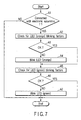
- FIG. 7 is a flowchart for the procedure for state display control executed at the fuel cell unit 2 of the electronic apparatus system.
- the microcomputer 21 examines whether or not the fuel cell unit 2 has been installed in the electronic apparatus 1 (step A1). If it has been installed (YES in step A1), the microcomputer 21 examines whether or not a phenomenon needing the blinking of the LED (orange) 27a has occurred, on the basis of the sensed data from the various sensors, including the liquid level sensor 2231, temperature sensor 2251, and acceleration sensor 25 (step A3).
- the microcomputer 21 If a phenomenon needing the blinking of the LED (orange) 27a has occurred (NO in step A3), the microcomputer 21 blinks the LED (orange) 27a (step A3). In addition, the microcomputer 21 examines whether or not a phenomenon needing the blinking of the LED (green) 27b has occurred, on the basis of the sensed data from the various sensors, including the installation and removal sensor 2231, liquid level sensor 2231, and temperature sensor 2251 (step A5). Then, if a phenomenon needing the blinking of the LED (green) 27b has occurred (NO in step A6), the microcomputer 21b blinks the LED (orange) 27a (step A7).
- the state display control process is shown in time sequence in the form of step A1 to A7. Actually, however, when a phenomenon needing the blinking of the LEDS 27a, 27b has taken place, the occurrence of the phenomenon triggers the execution of an event-driven process of blinking the LEDs 27a, 27b.
- a single LED capable of emitting a plurality of colored rays of light may be provided.
- a single-color LED may be provided and its lightening pattern may be changed, which enables the occurrence of a plurality of errors to be displayed.
- the electronic apparatus system it is realized that various notices are given by using a display unit provided on the fuel cell side.
Landscapes
- Engineering & Computer Science (AREA)
- Theoretical Computer Science (AREA)
- Physics & Mathematics (AREA)
- Computer Hardware Design (AREA)
- General Physics & Mathematics (AREA)
- General Engineering & Computer Science (AREA)
- Sustainable Energy (AREA)
- Life Sciences & Earth Sciences (AREA)
- Sustainable Development (AREA)
- Human Computer Interaction (AREA)
- Electrochemistry (AREA)
- General Chemical & Material Sciences (AREA)
- Chemical Kinetics & Catalysis (AREA)
- Chemical & Material Sciences (AREA)
- Manufacturing & Machinery (AREA)
- Power Engineering (AREA)
- Mathematical Physics (AREA)
- Fuel Cell (AREA)
Abstract
Description
Claims (14)
- A fuel cell unit characterized by comprising:a fuel cell (22);sensing means (2212, 2231, 2251, 25) for sensing an abnormal state of the fuel cell; anddisplay means (27a, 27b) for notifying a user of the abnormal state when the sensing means has sensed the abnormal state.
- The fuel cell unit according to claim 1, characterized by further comprising:connection detecting means (21) for detecting a presence or absence of a connection with an electronic apparatus operable using electric power supplied from the fuel cell, andthe display means notifies the user of the abnormal state, when the connection detecting means has detected a connection with the electronic apparatus and' the sensing unit has sensed the abnormal state.
- The fuel cell unit according to claim 2, characterized by further comprising notifying means (21) for notifying the electronic apparatus that the abnormal state has been sensed, when the sensing means has sensed the abnormal state.
- The fuel cell unit according to claim 1, characterized in that the sensing means senses whether or not an inclination of the fuel cell unit has exceeded a predetermined angle, and the display means notifies the user that the inclination has exceeded the predetermined angle when the sensing unit determines that the inclination of the fuel cell unit has exceeded the predetermined angle.
- The fuel cell unit according to claim 1, characterized in that the sensing means determines whether or not a temperature at an activation of the fuel cell falls in a predetermined temperature range, and the display means notifies the user that the temperature does not fall in the predetermined temperature range when the sensing means determines that the temperature at the activation of the fuel cell does not fall in the predetermined temperature range.
- The fuel cell unit according to claim 1, characterized in that the sensing means determines whether or not a temperature during an operation of the fuel cell falls in a predetermined temperature range, and the display means notifies the user that the temperature does not fall in the predetermined temperature range when the sensing means determines that the temperature during the operation of the fuel cell does not fall in the predetermined temperature range.
- The fuel cell unit according to claim 1, characterized in that the fuel cell has a power generating portion (225) and an auxiliary mechanism (224) for supplying fuel to the power generating portion, and
the sensing means senses whether or not the auxiliary mechanism has stopped, and the display means notifies the user that the auxiliary mechanism has stopped when the sensing unit determines that the auxiliary mechanism has stopped. - The fuel cell unit according to claim 1, characterized in that the fuel cell has a mixing tank (223) for mixing fuel used for power generation with water, and
the sensing means senses whether or not the amount of liquid in the mixing tank falls in a predetermined capacity range, and the display means notifies the user that the amount of liquid does not fall in the predetermined capacity range when the sensing unit determines that the amount of liquid in the mixing tank does not fall in the predetermined capacity range for a predetermined time or longer continuously. - The fuel cell unit according to claim 1,
characterized by further comprising:a fuel tank installing portion (221) which allows a fuel tank (2211) for storing fuel used for power generation in the fuel cell to be installed and removed, andthe sensing means senses whether or not the fuel tank has been installed in the fuel tank installing portion, and the display means notifies the user that the fuel tank has not been installed in the fuel tank installing portion when the sensing unit determines that the fuel tank has not been installed in the fuel tank installing portion. - The fuel cell unit according to claim 1, characterized by further comprising:a fuel tank (2211) for storing fuel for the fuel cell, andthe sensing means senses whether or not a remaining amount of fuel in the fuel tank has fallen below a predetermined value, and the display means notifies the user that the remaining amount has fallen below the predetermined value when the sensing means determines that the remaining amount of fuel in the fuel tank has fallen below the predetermined value.
- A state display control method for a fuel cell unit with a fuel cell, characterized by comprising the steps of:detecting (A1) a presence or absence of a connection with an electronic apparatus operable using electric power supplied from the fuel cell;determining (A2, A5) a state of the operation of the fuel cell unit; anddisplaying (A4, A7) an operating state of the fuel cell unit on the basis of the result of the determination, when a connection with the electronic apparatus has been detected.
- A state display control method for a fuel cell unit with a fuel cell, characterized by comprising the steps of:detecting (A1) a presence or absence of a connection with an electronic apparatus operable using electric power supplied from the fuel cell;detecting (A2, A5) an abnormal state of the fuel cell unit when a connection with the electronic apparatus has been detected; andnotifying (A4, A7) a user of the abnormal state of the fuel cell unit by use of a display unit provided in the fuel cell unit, when the abnormal state has been detected.
- A state display control method for a fuel cell unit with a fuel cell and an electronic apparatus operable using electric power supplied from the fuel cell unit, the state display control method characterized by comprising the steps of:determining (A2, A5) an operating state of the fuel cell unit;notifying (A4) a user of the occurrence of a first abnormality by use of a display unit provided in the fuel cell unit when the determination is shown that the first abnormality has occurred; andnotifying (A7) the occurrence of a second abnormality to the electronic apparatus when the determination is shown that the second abnormality has occurred.
- The state display control method according to claim 13, characterized by further comprising the step of:notifying a user of the occurrence of the second abnormality by use of a display portion provided in the electronic apparatus when the electronic apparatus receives the notification of the occurrence of the second abnormality.
Applications Claiming Priority (2)
| Application Number | Priority Date | Filing Date | Title |
|---|---|---|---|
| JP2003057467A JP3830910B2 (en) | 2003-03-04 | 2003-03-04 | Fuel cell unit and status display control method |
| JP2003057467 | 2003-03-04 |
Publications (2)
| Publication Number | Publication Date |
|---|---|
| EP1455402A1 true EP1455402A1 (en) | 2004-09-08 |
| EP1455402B1 EP1455402B1 (en) | 2008-08-13 |
Family
ID=32821186
Family Applications (1)
| Application Number | Title | Priority Date | Filing Date |
|---|---|---|---|
| EP04004527A Expired - Lifetime EP1455402B1 (en) | 2003-03-04 | 2004-02-27 | Fuel cell unit and operational state display control method |
Country Status (4)
| Country | Link |
|---|---|
| US (1) | US7569295B2 (en) |
| EP (1) | EP1455402B1 (en) |
| JP (1) | JP3830910B2 (en) |
| DE (1) | DE602004015656D1 (en) |
Cited By (6)
| Publication number | Priority date | Publication date | Assignee | Title |
|---|---|---|---|---|
| EP1455403A3 (en) * | 2003-03-04 | 2006-05-17 | Kabushiki Kaisha Toshiba | Electronic apparatus, and state display control method |
| WO2006092149A1 (en) * | 2005-03-03 | 2006-09-08 | Von Scholten Management Group Aps | Power supply unit with alarm device |
| EP1804323A1 (en) * | 2005-12-28 | 2007-07-04 | Yamaha Hatsudoki Kabushiki Kaisha | Fuel cell system and operating method thereof |
| EP2001071A1 (en) * | 2007-04-20 | 2008-12-10 | Honeywell International Inc. | Fuel cells used to supplement power sources for aircraft equipment |
| EP2038955A4 (en) * | 2006-05-22 | 2012-01-11 | Idatech Llc | Hydrogen-producing fuel processing systems with a liquid leak detection system |
| WO2012005810A1 (en) * | 2010-06-16 | 2012-01-12 | Apple Inc. | Fuel cell powered portable computing device with bidirectional communication link there between |
Families Citing this family (14)
| Publication number | Priority date | Publication date | Assignee | Title |
|---|---|---|---|---|
| JP2006049175A (en) * | 2004-08-06 | 2006-02-16 | Sanyo Electric Co Ltd | Fuel cell system |
| JP4568122B2 (en) * | 2005-01-05 | 2010-10-27 | シャープ株式会社 | Flat panel display device with fuel cell |
| JP4410722B2 (en) * | 2005-05-06 | 2010-02-03 | 株式会社日立製作所 | Power supply |
| JP2007026832A (en) * | 2005-07-14 | 2007-02-01 | Toshiba Corp | Information processing apparatus and operation control method |
| JP4749088B2 (en) * | 2005-08-26 | 2011-08-17 | 三洋電機株式会社 | Operation method of fuel cell power generator |
| KR100686846B1 (en) * | 2005-11-09 | 2007-02-26 | 삼성에스디아이 주식회사 | Fuel cell system |
| JP4870980B2 (en) * | 2005-12-14 | 2012-02-08 | 株式会社東芝 | Fuel cell system and control method thereof |
| JP5152614B2 (en) * | 2006-05-23 | 2013-02-27 | トヨタ自動車株式会社 | Fuel cell system |
| JP2008010367A (en) * | 2006-06-30 | 2008-01-17 | Toyota Motor Corp | Fuel cell diagnostic apparatus and diagnostic method |
| US8047073B2 (en) * | 2007-05-14 | 2011-11-01 | Samsung Sdi Co., Ltd. | Capacitive liquid level detector for direct methanol fuel cell systems |
| JP2009016270A (en) * | 2007-07-06 | 2009-01-22 | Toshiba Corp | Electronics |
| JP2009187830A (en) * | 2008-02-07 | 2009-08-20 | Casio Comput Co Ltd | Electronic device and fuel cell management system |
| JP4691189B1 (en) * | 2009-11-25 | 2011-06-01 | 株式会社東芝 | Direct methanol fuel cell |
| US20130140902A1 (en) * | 2011-12-06 | 2013-06-06 | Research In Motion Limited | Fuel cell recovery time system |
Citations (8)
| Publication number | Priority date | Publication date | Assignee | Title |
|---|---|---|---|---|
| US4968566A (en) * | 1988-08-04 | 1990-11-06 | Siemens Aktiengesellschaft | Arrangement for recovering water from a fuel cell battery |
| US20010052433A1 (en) * | 2000-04-14 | 2001-12-20 | Harris Donald B. | Hybrid power supply module |
| US20020055029A1 (en) * | 2000-08-01 | 2002-05-09 | Kyoji Hayashi | Electronic apparatus using fuel cell assembly |
| JP2002175827A (en) * | 2000-12-08 | 2002-06-21 | Sanyo Electric Co Ltd | Remote control type fuel cell power supply equipment |
| EP1306918A2 (en) * | 2001-10-29 | 2003-05-02 | Hewlett-Packard Company | Replaceable fuel cell apparatus having information storage device |
| US20030143447A1 (en) * | 2002-01-31 | 2003-07-31 | Toyota Jidosha Kabushiki Kaisha | Fuel cells power generation system |
| JP2003303609A (en) * | 2002-04-11 | 2003-10-24 | Canon Inc | Information equipment |
| JP2004111212A (en) * | 2002-09-18 | 2004-04-08 | Yamaha Motor Co Ltd | Fuel cell system |
Family Cites Families (9)
| Publication number | Priority date | Publication date | Assignee | Title |
|---|---|---|---|---|
| JPH03250564A (en) | 1990-02-28 | 1991-11-08 | Toshiba Corp | Fuel cell power generating system |
| JPH04172539A (en) | 1990-11-07 | 1992-06-19 | Toshiba Corp | Power supply condition display unit |
| JP3509349B2 (en) | 1995-12-20 | 2004-03-22 | 三洋電機株式会社 | Hybrid fuel cell |
| JPH09223512A (en) | 1996-02-16 | 1997-08-26 | Fuji Electric Co Ltd | Fuel cell abnormality monitoring method and apparatus |
| JP4487231B2 (en) | 2001-01-15 | 2010-06-23 | カシオ計算機株式会社 | Power generation module, power supply system and device |
| JP2002240535A (en) | 2001-02-13 | 2002-08-28 | Sanyo Electric Co Ltd | Cabin monitoring system |
| JP2002246037A (en) | 2001-02-20 | 2002-08-30 | Yamaha Motor Co Ltd | Fuel cell unit for electric vehicles |
| JP4155021B2 (en) | 2002-02-28 | 2008-09-24 | カシオ計算機株式会社 | Power generation type power supply and electronic equipment |
| JP2004227139A (en) * | 2003-01-21 | 2004-08-12 | Toshiba Corp | Electronic device and operation control method thereof |
-
2003
- 2003-03-04 JP JP2003057467A patent/JP3830910B2/en not_active Expired - Fee Related
-
2004
- 2004-02-27 DE DE602004015656T patent/DE602004015656D1/en not_active Expired - Fee Related
- 2004-02-27 EP EP04004527A patent/EP1455402B1/en not_active Expired - Lifetime
- 2004-03-02 US US10/790,240 patent/US7569295B2/en not_active Expired - Fee Related
Patent Citations (8)
| Publication number | Priority date | Publication date | Assignee | Title |
|---|---|---|---|---|
| US4968566A (en) * | 1988-08-04 | 1990-11-06 | Siemens Aktiengesellschaft | Arrangement for recovering water from a fuel cell battery |
| US20010052433A1 (en) * | 2000-04-14 | 2001-12-20 | Harris Donald B. | Hybrid power supply module |
| US20020055029A1 (en) * | 2000-08-01 | 2002-05-09 | Kyoji Hayashi | Electronic apparatus using fuel cell assembly |
| JP2002175827A (en) * | 2000-12-08 | 2002-06-21 | Sanyo Electric Co Ltd | Remote control type fuel cell power supply equipment |
| EP1306918A2 (en) * | 2001-10-29 | 2003-05-02 | Hewlett-Packard Company | Replaceable fuel cell apparatus having information storage device |
| US20030143447A1 (en) * | 2002-01-31 | 2003-07-31 | Toyota Jidosha Kabushiki Kaisha | Fuel cells power generation system |
| JP2003303609A (en) * | 2002-04-11 | 2003-10-24 | Canon Inc | Information equipment |
| JP2004111212A (en) * | 2002-09-18 | 2004-04-08 | Yamaha Motor Co Ltd | Fuel cell system |
Cited By (12)
| Publication number | Priority date | Publication date | Assignee | Title |
|---|---|---|---|---|
| EP1455403A3 (en) * | 2003-03-04 | 2006-05-17 | Kabushiki Kaisha Toshiba | Electronic apparatus, and state display control method |
| WO2006092149A1 (en) * | 2005-03-03 | 2006-09-08 | Von Scholten Management Group Aps | Power supply unit with alarm device |
| EP1804323A1 (en) * | 2005-12-28 | 2007-07-04 | Yamaha Hatsudoki Kabushiki Kaisha | Fuel cell system and operating method thereof |
| US20070178343A1 (en) * | 2005-12-28 | 2007-08-02 | Yamaha Hatsudoki Kabushiki Kaisha | Fuel cell system and operating method thereof |
| US8329349B2 (en) | 2005-12-28 | 2012-12-11 | Yamaha Hatsudoki Kabushiki Kaisha | Fuel cell system and operating method thereof |
| EP2038955A4 (en) * | 2006-05-22 | 2012-01-11 | Idatech Llc | Hydrogen-producing fuel processing systems with a liquid leak detection system |
| EP2001071A1 (en) * | 2007-04-20 | 2008-12-10 | Honeywell International Inc. | Fuel cells used to supplement power sources for aircraft equipment |
| WO2012005810A1 (en) * | 2010-06-16 | 2012-01-12 | Apple Inc. | Fuel cell powered portable computing device with bidirectional communication link there between |
| AU2011276993B2 (en) * | 2010-06-16 | 2014-06-26 | Apple Inc. | Fuel cell powered portable computing device with bidirectional communication link there between |
| US8980491B2 (en) | 2010-06-16 | 2015-03-17 | Apple Inc. | Fuel cell system to power a portable computing device |
| US9917340B2 (en) | 2010-06-16 | 2018-03-13 | Apple Inc. | Fuel cell system to power a portable computing device |
| US10790561B2 (en) | 2010-06-16 | 2020-09-29 | Apple Inc. | Portable computing device for external fuel cell control |
Also Published As
| Publication number | Publication date |
|---|---|
| JP2004265834A (en) | 2004-09-24 |
| US7569295B2 (en) | 2009-08-04 |
| JP3830910B2 (en) | 2006-10-11 |
| US20040224198A1 (en) | 2004-11-11 |
| DE602004015656D1 (en) | 2008-09-25 |
| EP1455402B1 (en) | 2008-08-13 |
Similar Documents
| Publication | Publication Date | Title |
|---|---|---|
| US7569295B2 (en) | Fuel cell unit and state display control method | |
| EP1306918B1 (en) | Replaceable fuel cell apparatus having information storage device | |
| US20040219398A1 (en) | Fuel cell control and data reporting | |
| KR19980065225A (en) | Computer with Battery Detection and Control | |
| US7216246B2 (en) | Electronic apparatus and supply power setting method for the apparatus | |
| JP3764429B2 (en) | Electronic device and power supply switching control method for electronic device | |
| EP1453134A1 (en) | Electronic apparatus, electronic system, and method of controlling operation of the same | |
| US7247399B2 (en) | Electronic apparatus and method of controlling operation of the same | |
| US20050031916A1 (en) | Electronic apparatus, fuel tank unit, and method of controlling a power supply for the electronic apparatus | |
| CN100426621C (en) | Electronic apparatus system, and operation control method | |
| US20040234828A1 (en) | Electronic apparatus, fuel cell unit, and method of controlling the operation of the electronic apparatus | |
| CN100386710C (en) | Electronic equipment, battery unit and working mode switching method | |
| US20040224199A1 (en) | Electronic apparatus, fuel cell unit, and state display control method | |
| KR100512736B1 (en) | Portable Computer | |
| US20050048330A1 (en) | Electronic system and power supply method | |
| JP4585475B2 (en) | Fuel cell unit | |
| JP2002124226A (en) | Information processing device capable of using secondary battery and dry battery, and dry battery pack detachable from the information processing device | |
| JPH0742201Y2 (en) | Electronics | |
| KR20050012403A (en) | Power supply system of portable device and method of controlling the same | |
| JP2006048681A (en) | Electronic device and status display control method | |
| JPH07319589A (en) | Computer system | |
| JP2005235784A (en) | Electronic device system and operation control method | |
| JP2006040742A (en) | Fuel cell remaining time calculation device and fuel cell remaining time display device | |
| JP2009087747A (en) | Electronics |
Legal Events
| Date | Code | Title | Description |
|---|---|---|---|
| PUAI | Public reference made under article 153(3) epc to a published international application that has entered the european phase |
Free format text: ORIGINAL CODE: 0009012 |
|
| 17P | Request for examination filed |
Effective date: 20040227 |
|
| AK | Designated contracting states |
Kind code of ref document: A1 Designated state(s): AT BE BG CH CY CZ DE DK EE ES FI FR GB GR HU IE IT LI LU MC NL PT RO SE SI SK TR |
|
| AX | Request for extension of the european patent |
Extension state: AL LT LV MK |
|
| AKX | Designation fees paid |
Designated state(s): DE FR GB |
|
| GRAP | Despatch of communication of intention to grant a patent |
Free format text: ORIGINAL CODE: EPIDOSNIGR1 |
|
| GRAS | Grant fee paid |
Free format text: ORIGINAL CODE: EPIDOSNIGR3 |
|
| GRAA | (expected) grant |
Free format text: ORIGINAL CODE: 0009210 |
|
| AK | Designated contracting states |
Kind code of ref document: B1 Designated state(s): DE FR GB |
|
| REG | Reference to a national code |
Ref country code: GB Ref legal event code: FG4D |
|
| REF | Corresponds to: |
Ref document number: 602004015656 Country of ref document: DE Date of ref document: 20080925 Kind code of ref document: P |
|
| PGFP | Annual fee paid to national office [announced via postgrant information from national office to epo] |
Ref country code: DE Payment date: 20090219 Year of fee payment: 6 |
|
| PLBE | No opposition filed within time limit |
Free format text: ORIGINAL CODE: 0009261 |
|
| STAA | Information on the status of an ep patent application or granted ep patent |
Free format text: STATUS: NO OPPOSITION FILED WITHIN TIME LIMIT |
|
| PGFP | Annual fee paid to national office [announced via postgrant information from national office to epo] |
Ref country code: GB Payment date: 20090225 Year of fee payment: 6 |
|
| 26N | No opposition filed |
Effective date: 20090514 |
|
| PGFP | Annual fee paid to national office [announced via postgrant information from national office to epo] |
Ref country code: FR Payment date: 20090213 Year of fee payment: 6 |
|
| GBPC | Gb: european patent ceased through non-payment of renewal fee |
Effective date: 20100227 |
|
| REG | Reference to a national code |
Ref country code: FR Ref legal event code: ST Effective date: 20101029 |
|
| PG25 | Lapsed in a contracting state [announced via postgrant information from national office to epo] |
Ref country code: FR Free format text: LAPSE BECAUSE OF NON-PAYMENT OF DUE FEES Effective date: 20100301 |
|
| PG25 | Lapsed in a contracting state [announced via postgrant information from national office to epo] |
Ref country code: DE Free format text: LAPSE BECAUSE OF NON-PAYMENT OF DUE FEES Effective date: 20100901 |
|
| PG25 | Lapsed in a contracting state [announced via postgrant information from national office to epo] |
Ref country code: GB Free format text: LAPSE BECAUSE OF NON-PAYMENT OF DUE FEES Effective date: 20100227 |