CROSS-REFERENCE TO RELATED APPLICATION
The present application claims priority under 35 U.S.C. §119 to Japanese Patent
Application Nos. 2003-036412 filed February 1, 2003, Japanese 2003-037303, filed
February 14, 2003, 2003-036751, filed February 14, 2003, and 2003-036527, filed
February 14, 2003, the entire contents of which are hereby incorporated by reference.
BACKGROUND OF THE INVENTION
1. Field of the Invention
The present invention relates to a riding simulation system for providing an
operator with a pseudo-experience of a running condition of a motorcycle by
displaying scenery seen to the rider as a visual image on a display based on an
operating condition of operation by the operator.
2. Description of Background Art
Hitherto, riding simulation systems for providing an operator with a pseudo-experience
of running conditions of a motorcycle by displaying various running
conditions on a display in response to various operations performed by the operator
have been adopted for the purpose of a play, an education of operation of the
motorcycle, or the like.
For example, a riding simulation system served to play has a structure in which
a steering handle shaft portion extending toward the upper side of a base member
having a lower surface formed to be a roughly flat surface shape is provided, and
steering handles extending leftwards and rightwards are disposed at a top portion of
the steering handle shaft portion.
In addition, the steering handles are fitted respectively with a right lever
functioning as a brake lever for a front wheel and a left lever for a clutch changeover
operation, and an accelerating operation of the motorcycle displayed on the display is
. effected through a right grip for acceleration which is provided turnably at a right end
portion of the steering handles.
With the riding simulation system mounted on a flat surface such as a floor, the
player grips the steering handles turns the steering handles with the steering handle
shaft portion as a center according to the operating condition, or turns the right grip as
required to effect an accelerating operation of the motorcycle displayed on the display
for play, or operates the right ever and the left lever to effect deceleration, and
performs gear change operations, whereby the player gets a pseudo-experience of
operations of the motorcycle displayed on the display for play (see, for example,
Japanese Patent Laid-open No. 2002-113264 (paragraphs [0010] to [0021]).
Meanwhile, an actual motorcycle is provided, on the lower side of a roughly
central portion thereof, with a foot brake pedal operated by the rider through his foot,
and a gear change pedal for gear change operations which is displaced upwards or
downwards by the rider through his foot.
In the riding simulation system according to Japanese Patent Laid-open No.
2002-113264, only the steering handles, the right lever functioning as the brake lever
for the front wheel, and the left lever for clutch changeover operations are provided;
namely, a foot brake pedal and a gear change pedal for performing a gear change
operation when displaced upwards or downwards by the rider through his foot are not
provided.
In view of the above, it is assumed that a pedal unit (not shown) comprising a
foot brake pedal and a gear change pedal is provided on the floor surface or the like
independently from the steering handle for the purpose of obtaining an operating
feeling more similar to that on an actual motorcycle. Based on the assumption,
however, an operation of kicking the gear change pedal upwards is needed in raising
the gear change gear ratio. In this case, the pedal unit itself mounted on the floor
surface or the like is lifted up from the floor surface or the like by this operation,
resulting in that it is difficult for the player to perform stable operations.
In addition, there is a request for getting pseudo-experiences of running
conditions of various vehicle forms of motorcycles by use of a single riding simulation
system.
In addition, conventionally there has been developed a riding simulation system
in which a dummy motorcycle and a display are combined with each other, a screen
display is varied according to operations on a steering handle and an accelerator, and a
dummy engine sound is generated, thereby providing the operator with a pseudo-experience
of running conditions.
In such a riding simulation system, in order to further enhance the ambience,
there has been proposed a system in which a motor for a dummy engine vibration is
mounted to an end portion of the steering handle, and the rotating speed of the motor is
controlled according to the rotating speed of a dummy engine, thereby generating
dummy vibrations (see, for example, Japanese Patent Laid-open No. Hei 5-23095
(paragraph [0039], FIG. 14).
In this case, the motor for the dummy engine vibration is desirably so
constituted that it is easy to replace and repair at the time of maintenance or the like.
On the other hand, since the motor is a means, which vibrates in itself, the motor must
be securely fixed so as not to generate a needless chatter other than the dummy
vibration.
Further, Japanese Patent Laid-open No. Hei 5-88605 (paragraph [0028], Fig.
14)has proposed a motorcycle riding simulation system in which the light emitted from
a video apparatus is not shielded by the operator and which provides an image easy to
see for the operator (see Patent Reference 1).
A mimic motorcycle constituting the riding simulation system disclosed in
Japanese Patent Laid-open No. Hei 5-88605 has a structure in which a gear change
mechanism including a change pedal is provided, and a gear change switch (sensor) for
detecting that a shift-down or shift-up has been performed by a displacement motion
through the change pedal is provided additionally.
Namely, with the gear change switch energized or de-energized under a
displacement action of the change pedal, it is detected that a gear change such as a
shift-up or a shift-down has been performed.
Meanwhile, in the riding simulation system disclosed in Japanese Patent Laid-open
No. Hei 5-88605, a gear change made by operating the change pedal results only
in that the gear change switch is pressed; therefore, the click feeling at the time of a
gear change in an actual motor cycle cannot be obtained, and the operating feeling at
the time of a gear change in the riding simulation system is far from that in the actual
motorcycle.
Still further In view of the above, Japanese Patent Laid-open No. Hei 5-88605(paragraph
[0020], Fig. 9) has proposed a motorcycle riding simulation system
in which the light emitted from a video apparatus is not shielded by the operator and
which provides an image easy to see for the operator
A mimic motorcycle in the riding simulation system disclosed in Japanese
Patent Laid-open No. Hei 5-88605 (paragraph [0020], Fig. 9) is provided with a
steering handle moving motor for applying to a steering handle a reaction force
corresponding to an operation of the steering handle by the operator, and is so
constructed that a steering handle operating feeling similar to that on an actual
motorcycle can be obtained.
Meanwhile, in the industry, there is a request for a structure in which the above-mentioned
steering handle moving motor is replaced by a simple mechanism. To
meet the request, therefore, it may be contemplated to generate a reaction force when
the steering handle is turned rightwards or leftwards, by use of two coil springs for a
steering handle shaft for turnably supporting the steering handle. This approach,
however, has the problem that a large space is required for mounting the two coil
springs.
On the other hand, when it is planned to generate both leftward and rightward
reaction forces by use of a single coil spring, a gap is generated between the coil spring
and the steering handle shaft, resulting in the generation of chatter.
SUMMARY AND OBJECTS OF THE INVENTION
The present invention has been made in consideration of the above-mentioned
problems and the like.
Accordingly, a first object of the present invention is to provide a riding
simulation system with which more stabler operations can be achieved and which
permits the operator to get pseudo-experiences of running conditions of various
vehicle forms of motorcycles.
In order to attain the above object, a first aspect of the present invention
provides a riding simulation system for providing an operator with a pseudo-experience
of running conditions of a motorcycle by displaying scenery seen to the
rider as a video image on a display based on the operating condition of operation by
the operator, the riding simulation system comprising a steering handle mechanism
gripped and operated by the operator, a step mechanism comprising a brake pedal and
a gear change pedal which are operated by the feet of the operator, a connection shaft
for connecting the steering handle mechanism and the step mechanism to each other,
the connection shaft provided to be extendable and contractable along the axial
direction thereof, and support means for supposing the steering handle mechanism or
the connection shaft.
According to the first aspect of the present invention, the steering handle
mechanism and the step mechanism are integrally connected to each other through the
extendable and contractable connection shaft, and the steering handle mechanism or
the connection shaft is supported by the support means. Therefore, when the riding
simulation system is installed, a lower end potion of the connection shaft is brought
into contact with and restricted by a floor surface or the like by extending or
contracting the connection shaft.
Accordingly, even when the brake pedal or the gear change pedal is operated by
the operator, the steering handle mechanism and the step mechanism of the riding
simulation system are not displaced attendant on the operation, so that the operator can
always operate stably the brake pedal and the gear change pedal.
Besides, with the connection shaft provided to be inclinable relative to the
steering handle mechanism or the step mechanism, the inclination angle of the
connection shaft can be set to an arbitrary angle according to the vehicle forms of
various motorcycles differing in the position of the step mechanism. As a result, the
operator can get pseudo-experiences of running conditions of various vehicle forms of
motorcycles differing in the position of the step mechanism relative to the position of
the steering handle mechanism.
A second object of the present invention is to provide a riding simulation
system which has a small number of component parts, is easy to maintain, and permits
the operator to experience dummy vibrations with an extremely high ambience.
In order to attain the second object, a second aspect of the present invention
provides a riding simulation system including a vibrator for a dummy engine vibration
in a steering handle mechanism and providing an operator with a pseudo-experience of
a running condition of a motorcycle by generating a vibration based on the operating
condition by the operator. The riding simulation system includes a taper surface
portion formed at an inner circumferential surface of a steering handle pipe
constituting the steering handle mechanism, the taper surface portion gradually
decreasing in diameter from the side of an end portion of the steering handle pipe, and
a bracket having an engaging portion for engagement with the end portion of the
steering handle pipe, having an outer circumferential surface gradually decreasing in
diameter from the side of the engaging portion, and being inserted into the taper
surface portion while holding the vibrator.
In this case, the outer circumferential surface decreasing in diameter of the
bracket holding the vibrator is inserted into the taper surface portion formed at the
inner circumferential surface of the end portion of the steering handle pipe, and the
engaging portion at the end portion of the bracket is engaged with the end portion of
the steering handle pipe, whereby the vibrator is fixed.
In addition, according to the second aspect of the present invention, there is
provided a riding simulation system including a vibrator for a dummy engine vibration
in a steering handle mechanism and providing an operator with a pseudo-experience of
a running condition of a motorcycle by generating a vibration based on the operating
condition by the operator. The riding simulation system includes a bracket screw-engaged
with an end portion of a steering handle pipe constituting the steering handle
mechanism. The vibrator is inserted into the inside of the steering handle pipe in the
state of being held by the bracket.
In this case, the vibrator is fixed through the bracket, which is screw-engaged
with the steering handle pipe.
Furthermore, the second aspect of the present invention provides a riding
simulation system including a vibrator for a dummy engine vibration in a steering
handle mechanism and providing an operator with a pseudo-experience of a running
condition of a motorcycle by generating a vibration based on the operating condition
by the operator.
The vibrator is inserted and held in the inside of one end portion of a steering
handle pipe constituting the steering handle mechanism, and a predetermined gap is
formed between an outer circumferential portion of the one end portion of the steering
handle pipe and a steering handle grip attached to the outer circumferential portion.
In this case, since the gap is formed between the steering handle pipe and the
steering handle grip, the vibration generated by the single vibrator is effectively
transmitted to both end portions of the steering handle grip without being attenuated.
Incidentally, when the steering handle grip is a throttle grip, a gap can be easily formed
between the steering handle pipe and the throttle grip. Besides, when the steering
handle pipe is composed of a single communicating pipe, the vibration can be securely
transmitted to the whole part of the steering handle pipe by using only the single
vibrator mounted to the steering handle grip side.
A third object of the present invention is to provide a riding simulation ystem in
which a pseudo-click feeling at the time of a gear change is generated with a simple
mechanism, whereby the operating feeling at the time of a gear change in the riding
simulation system can be made to be similar to that in an actual motorcycle.
In order to attain the third object, a third aspect the present invention provides a
riding simulation system for providing an operator with a pseudo-experience of
running conditions of a motorcycle by displaying scenery seen to the rider as a video
image on a display based on an operating condition upon an operation by the operator
and detecting a gear change by a sensor provided at a gear change pedal, the riding
simulation system including click generating means for generating a click feeling
similar to a gear change in an actual motorcycle when a gear change is made by
operating the gear change pedal.
According to the third aspect of the present invention, when a gear change is
made by operating the gear change pedal, the click generating means generates a click
sound, for example, a "click", and a vibration similar to that at the time of a gear
change in an actual motorcycle. Therefore, the operator can get a pseudo-click
feeling at the time of a gear change, and the operating feeling at the time of a gear
change in the riding simulation system can be made to be similar to that in the actual
motorcycle.
In this case, the click generating means has a simple mechanism including a
ball member, and a hole portion in which the ball member is engaged when the gear
change pedal is in a center position. When a gear change is made by operating the
gear change pedal, the ball member is released from the hole portion and thereafter
again engaged in the hole portion, whereby a click sound and a vibration are generated.
A fourth object of the present invention is to provide a riding simulation system
in which reaction forces can be applied to a steering handle respectively when the
steering handle is turned leftwards and rightwards, by use of a single spring, without
generating chatter at the steering handle.
In order to attain the fourth object, a fourth aspect of the present invention
provides a riding simulation system for providing an operator with a pseudo-experience
of running conditions of a motorcycle by displaying scenery seen to the
rider as a video image on a display based on an operating condition of a dummy
operating mechanism operated by the operator, the riding simulation system including
a handle mechanism for operating a steering handle with a steering handle shaft
portion as a turning fulcrum by the operator, a frame portion for supporting the
steering handle shaft portion, and a single spring for applying a reaction force in a
direction opposite to the turning direction of the steering handle when the steering
handle is operated. The single spring is provided with a pair of clamping portions
projected outwards from the handle shaft portion so as to clamp the frame portion
therebetween.
According to the fourth aspect of the present invention, the single spring
comprising the pair of clamping portions projected outwards from the handle shaft
portion so as to clamp the frame portion therebetween is provided so that, when the
steering handle is operated, the single spring applies a reaction force in a direction
opposite to the turning direction of the steering handle. Therefore, generation of
chatter at the steering handle is obviated, and the reaction force can be generated by a
simple mechanism.
In this case, with elastic members interposed between the pair of clamping
portions of the spring and the frame portion, generation of gaps between the clamping
portions and the frame portion is obviated, generation of a chatter due to such gaps can
be prevented securely, and it is possible to operate the steering handle with a feeling
more similar to that on an actual motorcycle.
Further scope of applicability of the present invention will become apparent
from the detailed description given hereinafter. However, it should be understood
that the detailed description and specific examples, while indicating preferred
embodiments of the invention, are given by way of illustration only, since various
changes and modifications within the spirit and scope of the invention will become
apparent to those skilled in the art from this detailed description.
BRIEF DESCRIPTION OF THE DRAWINGS
The present invention will become more fully understood from the detailed
description given hereinbelow and the accompanying drawings which are given by
way of illustration only, and thus are not limitative of the present invention, and
wherein:
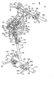
FIG. 1 is a perspective view of a riding simulation system according to an
embodiment of the present invention;
FIG. 2 is a side view of the riding simulation system shown in FIG. 1;
FIG. 3 is a plan view of the riding simulation system shown in FIG. 1;
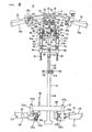
FIG. 4 is a front view of the riding simulation system shown in FIG. 1;
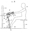
FIG. 5 is a side view showing the case where the riding simulation system
shown in FIG 1 is fixed on a table;
FIG. 6 is a side view showing the case where the riding simulation system
shown in FIG. 1 is fixed on the table and a pedal unit is inclined by a predetermined
angle to the operator side;
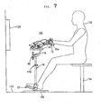
FIG. 7 is a side view of a riding simulation system according to another
embodiment of the present invention;
FIG. 8 is a side view of the riding simulation system of FIG. 7 in the condition
where the pedal mechanism has been detached;
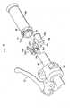
FIG. 9 is an exploded perspective view of a mount structure of a vibrator in the
riding simulation system shown in FIG. 1;
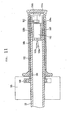
FIG. 10 is a sectional view of the mount structure shown in FIG. 9;
FIG. 11 is a perspective illustration of the vibrator;
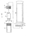
FIG 12 is an exploded view of another mount structure of the vibrator in the
riding simulation system shown in FIG. 1;
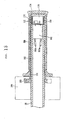
FIG. 13 is a sectional view of the mount structure shown in FIG. 12;
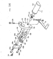
FIG. 14 is an exploded perspective view of a click generating means
constituting the riding simulation system shown in FIG. 1;
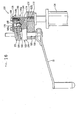
FIG 15 is a side vicw of the click generating means shown in FIG 14;
FIG. 16 is a cross-sectional view taken along line VII-VII of FIG. 15;
FIG. 17 is an illustration of operation of the click generating means shown in
FIG. 14;
FIG. 18 is a partly omitted side view showing a stopper member provided at one
end portion of a stem member and a return spring;
FIG. 19 is a partly sectional view showing the relationship in which a third main
frame is clamped between end portion of the return spring;
FIG. 20 is a partly sectional view showing the condition where the stopper
member shown in FIG. 19 is turned counterclockwise and a projection piece presses
the end portion of the return spring along the turning direction; and
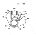
FIG 21 is a partly sectional view showing the condition where the stopper
member shown in FIG. 19 is turned clockwise and the projection piece presses the end
portion of the return spring along the turning direction.
DETAILED DESCRIPTION OF THE PREFERRED EMBODIMENTS
FIGS. 1 to 4 show the riding simulation system 10 according to the
embodiment of the present invention
The riding simulation system 10 (hereinafter referred to simply as the
simulation system 10) is comprised of a steering handle mechanism 12 which is
gripped by an operator 133 (sec FIGS. 5 to 8) and which is for steering a front wheel
of a motorcycle displayed on a display 128 described later, a frame body 14 for
turnably holding the steering handle mechanism 12, a connection shaft 16 supported
inclinably relative to the frame body 14 and provided to be extendable and
contractable, and a pedal mechanism 22 disposed at a lower end portion of the
connection shaft 16 and comprising a gear change pedal 18 and a brake pedal 20.
The steering handle mechanism 12 is comprised of a steering stem 24 (see FIG.
3) having an upper portion formed in a roughly fan-like shape, an elongate steering
handle 28 integrally held on the steering stem 24 through a holder 26, lever joint
portions 34a and 34b through which a clutch lever 30 and a brake lever 32 are held on
the steering handle 28, and left and right grips 36a and 36b covered with rubber or the
like which are mounted respectively to end portions of the steering handle 28.
The steering stem 24 is provided at its upper end portion with a roughly fan-like
mount surface, to which a pair of mount flanges 38 are connected roughly in parallel
through bolts 40 in such a manner as to project upwards. The mount flanges 38 are
each provided with a semi-circular recessed portion 42 corresponding to the outside
diameter oftbe steering handle 28.
In addition, a lower end portion of the steering stem 24 is integrally connected,
through a bolt 40, to an upper end portion of a stem member 46 inserted in a
cylindrical portion 44 of the frame body 14. The upper end portion of the stem
member 46 is thus connected with the steering stem 24, whereas a lower end portion of
the stem member 46 inserted in the cylindrical portion 44 of the frame body 14 is
inserted in a hole portion (not shown) formed in a roughly central portion of a bracket
48 connected to the frame body 14. Namely, the stem member 46 is turnably
supported by the cylindrical portion 44 and the hole portion of the bracket 48.
Furthermore, a spring 50 for such an urging as to ensure that the steering handle
28 connected to the stem member 46 is constantly located in a center position is
provided between the stem member 46 and the bracket 48.
The steering handle 28 is formed in a cylindrical shape from a pipe material or
the like, and both end portions of the steering handle 28 are bent at predetermined
angles toward the rear side of the simulation system 10.
A left end portion of the steering handle 28, as viewed in a direction toward the
front side of the simulation system 10, is fitted with a left grip 36a covered with rubber
or the like. Similarly, a right end portion of the steering handle 28 is fitted with a
right grip 36b formed of rubber or the like. The right grip 36b functions as a throttle
grip for performing an accelerating operation in the motorcycle displayed on the
display 128 when it is rotated toward the operator 133 (see FIGS. 5 to 8) by the
operator 133.
Roughly central portions of the steering handle 28 are mounted in the recessed
portions 42 (see FIG 1) of the mount flanges 38. With the pair of holders 26
mounted from upper portions of the mount flanges 38 and fastened with the bolts 40,
the steering handle 28 is clamped between the mount flanges 38 and the holders 26 and
is integrally fixed to the steering stem 24.
Furthermore, at positions spaced from both end portions of the steering handle
28 toward a roughly central portion of the steering handle 28 by a predetermined
length, the annular lever joint portions 34a and 34b are disposed in the manner of
surrounding the steering handle 28.
The lever joint portion 34a is disposed on the left side of the steering handle 28.
The lever joint portion 34a is integrally fitted with the clutch lever 30 on the front side
of the simulation system 10.
The clutch lever 30 is shaft-supported so as to be turnable relative to the lever
joint portion 34a. With the clutch lever 30 gripped toward the steering handle 28
when a gear changing operation for gears is performed by the operator 133 (see FIGS.
5 to 8), a clutch in the motorcycle displayed on the display 128 is disconnected,
resulting in the condition where a gear changing operation can be performed with the
gear change pedal 18 described later.
Incidentally, the clutch lever 30 is disposed only in the case of a motorcycle
provided with a manual transmission; in the case of a motorcycle provided with an
automatic transmission, a brake lever disposed in place of the clutch lever 30.
Besides, the lever joint portion 34b disposed on the right side of the steering
handle 28 is integrally fitted with the brake lever 32 on the front side of the simulation
system 10, similarly.
The brake lever 32 is shaft-supported so as to be turnable relative to the lever
joint portion 34b. With the brake lever 32 gripped toward the steering handle 28 by
the operator 133, the front wheel of the motorcyle displayed on the display 128 is set
into a braked condition.
The frame body 14 is comprised of three, first to third main frames 52a, 52b,
and 52c connected at equal angular intervals from the cylindrical portion 44 in which
the stem member 46 is inserted, a pair of sub-frames 54a and 54b connected to roughly
central portions of the first and second main frames 52a and 52b so as to extend toward
the front side of the simulation system 10, a cross frame 56 for connection between tip
end portions of the sub-frames 54a and 54b, and a connection frame 58 which connects
the first and second main frames 52a and 52b to each other and of which a roughly
central portion inclinably supports the connection shaft 16 through an inclination lock
mechanism 110. The connection frame 58 is disposed so as to position below the
cross frame 56 in parallel with each other.
The first to third main frames 52a to 52c are disposed at equal angular intervals,
with the cylindrical portion 44 as a center, and the two, first and second main frames
52a and 52b disposed to be symmetrical in the left and right directions from the
cylindrical portion 44 extend downwards while being curved. Tip end portions
extending on the lower side of the two, first and second main frames 52a and 52b are
formed to be roughly horizontal, and the tip end portions are provided with stopper
mechanisms 60 for fixing the frame body 14 to a flat-surfaced table 130 or the like.
The stopper mechanism 60 is provided roughly orthogonally to the first and
second main frames 52a and 52b, and is comprised of a pair of fixing bolts 62 screw-engaged
with tip end portions of the first and second main frames 52a and 52b, and
holding portions 64 formed to be enlarged radially outwards at upper end portions of
the fixing bolts 62. Incidentally, top faces of the holding portions 64 are formed to be
roughly flat. By turning the fixing bolts 62 scew-engaged with the first and second
main frames 52a and 52b, the fixing bolts 62 are vertically displaced along the axial
direction thereof.
In addition, the third main frame 52c disposed between the two, first and
second main frames 52a and 52b in the cylindrical portion 44 is curved downwards
from the cylindrical portion 44, to be connected to the cross frame 56.
A first detection unit 68 moved in conjunction with a clutch wire 66 through the
clutch lever 30 so as to detect the grip amount of the clutch lever 30 is disposed at the
top face of the sub-frame 54a on one side which is connected to the first main frame
52a.
In addition, a second detection unit 72 moved in conjunction with a brake wire
70 through the brake lever 32 so as to detect the grip amount of the brake lever 32 is
disposed at the top face of the sub-frame 54b on the other side which is connected to
the second main frame 52b.
Furthermore, a throttle opening angle detection unit 76 for detecting the
opening (turning amount) of the right grip 36b mounted to the steering handle 28
through a throttle wire 74 is disposed at the top face of the third main frame 52c
connected to the cross frame 56.
As shown in FIG. 3, the first detection unit 68 is comprised of a detection unit
main body 78 fixed to the sub-frame 54a through bolts 40, a first rotative pulley 80
shaft-supported turnably relative to the detection unit main body 78, a first return
spring 82 interposed between the detection unit main body 78 and the first rotative
pulley 80, and a first stopper portion 84 (see FIGS. 1 and 4) for restricting the turning
motion of the first rotative pulley 80.
The other end portion side of the clutch wire 66 having one end portion
connected to the clutch lever 30 is connected to the first rotative pulley 80. The first
return spring 82, by its springy force, applies a biasing force in the direction of pulling
the clutch wire 66 connected to the first rotative pulley 80. A sensor (not shown) for
detecting the turning amount of the first rotative pulley 80 is incorporated in the
detection unit main body 78. The turning amount of the first rotative pulley 80
detected by the sensor is outputted as a detection signal to a control unit (not shown),
through a connector 86 formed in the exterior of the detection unit main body 78.
Incidentally, the clutch lever 30 is set to be spaced apart from the steering
handle 28, by the pulling of the clutch wire 66 connected to the first rotative pulley 80
under the action of the springy force of the first return spring 82. In other words, the
clutch lever 30 is held in the state of being spaced by a predetermined spacing from the
steering handle 28.
Like the first detection unit 68 the second detection unit 72 is comprised of a
detection unit main body 78 fixed to the sub-frame 54b through bolts 40, a second
rotative pulley 88 shaft-supported turnably relative to the detection unit main body 78,
a second return spring 90 interposed between the detection unit main body 78 and the
second rotative pulley 88, and a second stopper portion 92 for restricting the turning
motion of the second rotative pulley 88.
The other end portion side of a brake wire 70 having one end portion connected
to the brake lever 32 is connected to the second rotative pulley 88. The second return
spring 90, by its springy force, applies a biasing force in the direction of pulling the
brake wire 70 connected to the second rotative pulley 88. A sensor (not shown) for
detecting the turning amount of the second rotative pulley 88 is incorporated in the
detection unit main body 78.
The turning amount of the second rotative pulley 88 detected by the sensor is
outputted as a detection signal to the control unit (not shown), through a connector 86
formed in the exterior of the detection unit main body 78.
Incidentally, the brake lever 32 is set to be spaced apart from the steering
handle 28, by the pulling of the brake wire 70 connected to the second rotative pulley
88 under the action of the springy force of the second return spring 90. In other
words, the brake lever 32 is held in the state of being spaced by a predetermined
spacing from the steering handle 28.
The throttle opening angle detection unit 76 has a structure in which one end
portion side of a turning plate 93 is turnably shaft-supported through a detection unit
main body 78 fixed to the third main frame 52c with bolts 40. A spring 94 for urging
the turning plate 93 in the direction of spacing away from the cylindrical portion 44 is
interposed between the turning plate 93 and the detection unit main body 78. In
addition, the other end portion side of a throttle wire 74 having one end portion
connected to the right grip 36b is connected to the other end portion side of the turning
plate 93.
Furthermore, a cable stopper 96 for holding the clutch wire 66, the brake wire
70 and the throttle wire 74 is mounted onto the top face of the third main frame 52c
through bolts 40, in the state of being spaced by a predetermined spacing from the
throttle opening angle detection unit 76. The cable stopper 96 is formed in a roughly
T shape in section, and has a structure in which the throttle wire 74 is inserted and held
in a groove portion 98a formed in a roughly central portion of the cable stopper 96,
and the clutch wire 66 connected to the clutch lever 30 is inserted and held in a groove
portion 98b formed on the right side of the cable stopper 96.
In addition, the brake wire 70 connected to the brake lever 32 is inserted and
held in a groove portion 98c formed on the left side of the cable stopper 96.
Incidentally, those portions of the clutch wire 66, the brake wire 70 and the
throttle wire 74 which are located between the cable stopper 96 and the clutch lever 30,
the brake lever 32 and the right grip 36b are each covered with a tubular cover tube
100.
The connection shaft 16 is formed to be elongate along the axial direction
thereof, and is comprised of a first shaft portion 102 supported inclinably relative to
the connection frame 58 in the frame body 14, a second shaft portion 104 in which the
first shaft portion 102 is inserted and which is formed to be slightly larger in diameter
than the first shaft portion 102, a step shaft 106 formed on the lower side of the second
shaft portion 104 roughly orthogonally to the axis of the second shaft portion 104, and
a support portion 108 formed at a lower end portion of the second shaft portion 104
roughly in parallel to the step shaft 106.
The inclination lock mechanism 110 for restricting and releasing an inclining
motion of the connection shaft 16 relative to the connection frame 58 is provided at an
upper end portion of the first shaft portion 102.
The inclination lock mechanism 110 is comprised of a fastening lever 112
having a screw portion and functioning for restricting and releasing the inclining
motion of the connection shaft 16, a clamp 114 disposd at a position facing a side
surface of the upper end of the first shaft 102, and a nut 116 screw-engaged with the
screw portion of the fastening lever 112 passed through through-holes formed in the
clamp 114 and an upper end portion of the first shaft portion 102. Namely, the
connection frame 58 is clamped between the upper end portion of the first shaft portion
102 and the clamp 114.
With the connection shaft 16 clamping the connection frame 58 being inclined
to a predetermined angle and with the fastening lever 112 being turned in a direction in
which the outer circumferential surface of the first shaft portion 102 is pressed by the
clamp 114, the spacing between the fastening lever 112 and the nut 116 is reduced
under a screw-engaging action between the screw portion of the fastening lever 112
and the nut 116, and the outer circumferential surface of the connection frame 58 is
pressed by the clamp 114. As a result, the inclining motion of the connection shaft 16
relative to the connection frame 58 is restricted.
On the other hand, the inside diameter of the second shaft portion 104 is
formed to be roughly equal to or slightly larger than the outside diameter of the first
shaft portion 102. Therefore, the first shaft portion 102 can be freely displaced inside
the second shaft portion 104 along the axial direction of the second shaft portion 104.
In addition, an extension/contraction lock mechanism 118 for restricting and
releasing the extending and contracting displacements of the first shaft portion 102
relative to the second shaft portion 104 by fastening the outer circumferential surface
of the second shaft portion 104 radially inwards is provided at an upper end portion of
the second shaft portion 104.
The extension/contraction lock mechanism 118 is comprised of a fastening
lever 112 having a screw portion and functioning for restricting and releasing the
extending and contracting displacements of the first shaft portion 102, a clamp 120 so
mounted as to surround an upper end portion of the second shaft portion 104, and a nut
116 screw-engaged with the screw portion of the fastening lever 112 passed through a
through-hole formed in the clamp 120.
Specifically, with the first shaft portion 102 displaced extendingly or
contractingly upwards or downwards along the axial direction to a desired position
under the condition of gripping the second shaft portion 104 and with the fastening
lever 112 turned so as to cause the clamp 120 to press the outer circumferential surface
of the second shaft portion 104 radially inwards, the spacing between the fastening
lever 112 and the nut 116 is reduced under the screw-engaging action between the
screw portion of the fastening lever 112 and the nut 116, and the outer circumferential
surface of the second portion is pressed radially inwards, so that the extending or
contracting displacement of the first shaft portion 102 relative to the second shaft
portion 104 is restricted.
In other words, the overall length of the connection shaft 16 composed of the
first and second shaft portions 102 and 104 can be regulated by the extension or
contraction, and the connection shat 16 can be fixed to an arbitrary length by
restricting the extension or contraction of the connection shaft 16 by the
extension/contraction lock mechanism 18.
In addition, the pedal mechanism 22 composed of the gear change pedal 18
operated by the operator 133 at the time of a gear change for gears and the brake pedal
for performing a braking operation at the time of deceleration are provided at both end
portions of the step shaft 106 formed on the lower side of the connection shaft 16.
Furthermore, the support portion 108 of the connection shaft 16 is formed to
extend in an orthogonal direction by a predetermined length from a lower end portion
of the second shaft portion 104. When the simulation system 10 is installed in a site,
the support portion 108 is grounded a floor surface 132 or the like, whereby the
simulation system 10 can be installed securely in a further stabler installation condition.
The pedal mechanism 22 is comprised of a brake pedal unit 109 disposed on
the right side of the step shaft 106, and a gear change pedal unit 111 disposed on the
left side of the step shaft 106. Namely, the brake pedal unit 109 is provided on the
side of the brake lever 32 in the steering handle mechanism 12, whereas the gear
change pedal unit 111 is provided on the side of the clutch lever 30 in the steering
handle mechanism 12.
The brake pedal unit 109 is comprised of a mount plate 122a connected to a
right end portion of the step shaft 106 through a screw member, a step 124 projecting
by a predetermined length in a direction of spacing away from the step shaft 106 of the
mount plate 122a, the brake pedal 20 which is spaced by a predetermined spacing
toward the front side of the simulation system 10 from the step 124 and which is
turnably mounted to the mount plate 122a through a pin member, and a turning amount
detection unit 125a which is mounted at a position facing the brake pedal 20 with the
mount plate 122a therebetween and which detects the turning amount of the brake
pedal 20.
The brake pedal 20 is formed in a roughly L shape, and is so mounted as to
project toward the front side of the simulation system 10 through the pin member
inserted in the mount plate 122. The brake pedal 20 is provided to be downwardly
turnable with the pin member as a fulcrum, and a return spring 126a for applying an
upward biasing force so as to constantly maintain the brake pedal 20 in a roughly
horizontal state is interposed between one end portion shaft-supported by the pin
member of the brake pedal 20 and the mount plate 122a.
Specifically, when the brake pedal 20 is stepped in downwards by the operator
133, the brake pedal 20 is turned with the one end portion shaft-supported by the pin
member as a fulcrum against the springy force of the return spring 126a, and the
turning amount of the brake pedal 20 is detected by the turning amount detection unit
125a. The turning amount of the brake pedal 20 detected by the turning amount
detection unit 125a is outputted as a detection signal to the control unit (not shown)
through a connector 86 connected to the turning amount detection unit 125a.
In addition, the gear change pedal unit 111 is comprised of a mount plate 122b
connected to a left end portion of the step shaft 106 through a screw member, a step
124 projecting by a predetermined length in a direction of spacing away from the
mount plate 122b, the gear change pedal 18 which is spaced by a predetermined
spacing toward the front side of the simulation system 10 from the step 124 and which
is provided turnably through the pin member attached to the mount plate 122b, and a
turning amount detection unit 125b which is mounted at a position facing the gear
change pedal 18 with the mount plate 122b therebetween and which detects the turning
amount of the gear change pedal 18.
Incidentally, the mount plates 122a and 122b are fitted over the step shaft 106
through hole portions, and the mount plates 122a and 122b are fixed to the step shaft
106 through fixing screws 127a and 127b (see FIGS. 1 and 4) screwed to upper
portions of the mount plates 122a and 122b. Namely, by loosening the fixing screws
127a and 127b, it is possible to rotate the mount plates 122a and 122b about the step
shaft 106 as a center.
The gear change pedal 18 is formed in a roughly L shape, and is so mounted
as to project toward the front side of the simulation system 10 through the pin member
inserted through the mount plate 122. The gear change pedal 18 is provided to be
turnable upwards and downwards with the pin member as a fulcrum, and a return
spring 126b for applying a biasing force so as to constantly maintain the gear change
pedal 18 in a roughly horizontal condition is interposed between one end portion shaft-supported
by the pin member of the gear change pedal 18 and the mount plate 122.
Specifically, when the gear change pedal 18 is pulled upwards or stepped in
downwards by the operator 133, the gear change pedal 18 is turned with the one end
portion shaft-supported by the pin member as a fulcrum, and the turning amount of the
gear change pedal 18 is detected by the turning amount detection unit 125b. The
turning amount of the gear change pedal 18 detected by the turning amount detection
unit 125b is outputted as a detection signal to the control unit (not shown) through a
connector 86 connected to the turning amount detection unit 125b. Incidentally, a
wire cable (not shown) connected to the connector 86 is contained in the inside of the
connection shaft 16, whereby the wire cable is prevented from being exposed to the
outside, and the wire cable can be prevented from breakage or the like.
The riding simulation system 10 according to the embodiment of the present
invention is basically constituted as above. Next, operations and functions or effects
of the riding simulation system 10 will be described below. First, a method of
mounting the simulation system 10 to a table 130 (see FIGS. 5 and 6) or the like will
be described.
First, as for example shown in FIGS. 5 and 6, the lower surfaces of the pair of
sub-frames 54a and 54b in the frame body 14 are seated on the top surface of a flat
plate portion 129 of the flat-surfaced table 130 on which the display 128 is mounted.
Then, the fixing bolts 62 of the stopper mechanisms 60 are turned to be displaced
upwards, whereby the top faces of the holding portions 64 formed at the upper portions
of the fixing bolts 62 are brought into contact with the lower surface of the table 130.
As a result, the table 130 is clamped between the sub-frames 54a and 54b and the
holding portions 64 of the stopper mechanisms 60. In other words, the simulation
system 10 is easily fixed to the table 130 with the sub-frames 54a and 54b and the
stopper mechanisms 60. Incidentally, as shown in FIGS. 5 and 6, the table 130 is
disposed on a floor surface 132 or the like through leg portions 131 connected to the
flat plate portion 129 and extending downwards roughly vertically.
Next, the axis of the connection shaft 16 supported by a lower portion of the
frame body 14 is inclined to a desired inclination angle against the vertical line
(see FIG. 2). In this case, first, the fastening lever 112 of the inclination lock
mechanism 110 provided at the upper end of the first shaft portion 102 is loosened by
turning, and the connection shaft 16 is inclined to a desired angle against the
connection frame 58. Incidentally, the inclination angle of the connection shaft
16 against the connection frame 58 can be set to an arbitrary angle according to the
position of the pedal mechanism 22 in various motorcycles such as an American type
one and a sportive type one.
In this case, the fixing screws 127a and 127b (see FIGS. 1 and 4) screw-engaged
with upper portions of the mount plates 122a and 122b in the brake pedal unit
109 and the gear change pedal unit 111 are loosened. Then, the mount plates 122a
and 122b are turned so as to set the gear change pedal 18 and the brake pedal 20 into a
roughly horizontal condition. With the gear change pedal 18 and the brake pedal 20
in the roughly horizontal condition, the fixing screws 127a and 127b are tightened,
whereby the mounting angles of the gear change pedal 18 and the brake pedal 20 are
fixed.
As for example shown in FIG. 5, in the case of an American type motorcycle,
the pedal mechanism 22 is located roughly directly on the lower side of the steering
handle mechanism 12, so that the connection shaft 16 is inclined toward the front side
of the simulation system 10 by a desired inclination angle 1 against the vertical line.
On the other hand, as shown in FIG 6, in the case of a sportive type
motorcycle, the pedal mechanism 22 is located on the rear side of the simulation
system 10 relative to the steering handle mechanism 12, so that the connection shaft 16
is inclined toward the rear side of the simulation system 10 by a desired inclination
angle 2 against the vertical line. Thus, with the single simulation system 10,
pseudo-experience of running conditions of a variety of vehicle forms of motorcycles
can be provided.
As shown in FIG 2, after the connection shaft 16 is inclined to the desired
inclination angle against the vertical line, the fastening lever 112 of the inclination
lock mechanism 110 is turned in a direction opposite to the above-mentioned direction,
whereby the connection frame 58 is fastened with the clamp 120. As a result, the
inclination angle of the connection frame 58 against the connection shaft 16 is
securely fixed.
Finally, the connection shaft 16 is extended or contracted to have a desired
length. In this case, first, the fastening lever 12 of the extension/contraction lock
mechanism 118 provided on the connection shaft 16 is loosened by turning, and, in the
condition where the first shaft portion 102 is gripped, the second shaft portion 104 is
extended or contracted so that the support portion 108 formed at the lower end portion
of the second shaft portion 104 is grounded on the floor surface 132 or the like.
Then, in the condition where the support portion 108 of the second shaft
portion 104 is grounded on the floor surface 132 or the like, the fastening lever 112 of
the extension/contraction lock mechanism 118 is turned in a direction opposite to the
above-mentioned direction, whereby the outer circumferential surface of the second
shaft portion 104 is fastened through the clamp 120. As a result, the connection shaft
16 is fixed in the condition where the support portion 108 thereof is grounded on the
floor surface 132 or the like. In other words, the length of the connection shaft 16 is
fixed at an arbitrary length by the extension/contraction lock mechanism 118.
Therefore, an upper portion of the simulation system 10 is integrally fixed to
the table 130 through the frame body 14, and the support portion 108 of the connection
shaft 16 constituting a lower portion of the simulation system 10 makes contact with
the floor surface 132, whereby the simulation system 10 is securely fixed.
Next, a method of operating the simulation system 10 mounted onto the table
130 or the like as above will be described.
First, as shown in FIG. 5, the operator 133 is seated on a chair 134 disposed on
the rear side of the simulation system 10, grips the right grip 36b of the steering handle
28 by his right hand, and grips the left grip 36a of the steering handle 28 by his left
hand.
Then, the operator 133 puts his right foot on the brake pedal 20 of the pedal
mechanism 22, and puts hits left foot on the gear change pedal 18 of the pedal
mechanism 22.
In this case, the pedal mechanism 22 on which both feet of the operator 133
are put is in contact with the floor surface 132 through the support portion 108 of the
connection shaft 16, so that the pedal mechanism 22 is maintained in a stable condition
without displacement even when the feet are put thereon.
After the preparatory stage as above-mentioned, the operator 133 operates the
right grip 36b functioning as a throttle of the steering handle 28, the brake lever 32 and
the clutch lever 30, whereby the throttle opening angle relating to the right grip 36b as
well as the grip amounts of the brake lever 32 and the clutch lever 30 are outputted as
detection signals to the control unit (not shown) by the throttle opening angle detection
unit 76, the first detection unit 68 and the second detection unit 72.
In addition, when the brake pedal 20 is operated by the operator 133, the
turning amount of the brake pedal 20 is detected by the turning amount detection unit
125a, and the detection signal is outputted to the control unit.
Furthermore, when the gear change pedal 18 is operated attendant on an
operation of the clutch lever 30 by the operator 133, a detection signal indicating that a
gear change has been done is outputted through the turning amount detection unit 125b
to the control unit.
Then, based on these detection signals, the control unit displays the running
condition of the simulation system 10 on the display 128 mounted on the table 130.
As described above, in the present embodiment, the connection shaft 16 is
provided at a lower portion of the frame body 14 with the inclination lock mechanism
110 therebetween so that it can be inclined to a desired inclination angle.
Therefore, the inclination angle of the connection shaft 16 can be set to an
arbitrary angle according to the vehicle forms of various motorcycles differing in the
position of the pedal mechanism 22 such as an American type one and a sportive type
one. As a result, the operator can get pseudo experiences of running conditions of
various vehicle forms of motorcyles differing in the position of the pedal mechanism
22 relative to the position of the steering handle mechanism 12, by use of the single
simulation system 10.
In other words, the pedal mechanism 22 can be set to an arbitrary position by
inclining the connection shaft 16 supported by the frame body 14 through the
inclination lock mechanism 110.
In addition, the pedal mechanism 22 mounted to the connection shaft 16 is
restricted in upward displacement by the stopper mechanisms 60, and is restricted in
downward displacement by the support portion 108 of the connection shaft 16 which is
in contact with the floor surface 132.
Therefore, the pedal mechanism 22 and the simulation system 10 as a whole
are prevented from being displaced upwards or downwards when the gear change
pedal 18 is operated upwards or downwards by the operator 133 through his foot. As
a result, the operator can perform stable operation at all times.
Furthermore, even where the height of the table 130 or the like to which the
frame body 14 is mounted is different, the support portion 108 of the connection shaft
16 can be securely brought into contact with the floor surface 132 or the like by
extending or contracting the connection shaft 16. Therefore, it is not necessary to
take the height of the table 130 or the like into consideration when the simulation
system 10 is installed, resulting in higher degree of freedom for installation site.
Next, a riding simulation system 150 according to another embodiment is
shown in FIG. 7. The same components as those in the riding simulation system
according to the above-described embodiment will be denoted by the same reference
symbols as used above, and detailed description thereof will be omitted.
The riding simulation system 150 according to the another embodiment of the
present invention differs from the riding simulation system 10 according to the above-described
embodiment in that a flat-surfaced mount plate 152 is provided at a lower
end portion of the connection shaft 16 in place of the support portion 108 formed at the
lower end portion of the connection shaft 16.
As shown in FIG. 7, the simulation system 150 is mounted on a floor surface
132 or the like through the flat-surfaced mount plate 152 which is formed at the lower
end portion of the connection shaft 16 in the state of being roughly orthogonal to the
axis of the connection shaft 16. An area of the mount plate 152 is formed a size
enough to mount the simulation system 150 with stability.
Therefore, the simulation system 150 can be installed by use of only the
mount plate 152, so that the simulation system 150 can be used even where a table 130
or the like for fixing the frame body 14 is absent in the vicinity. In other words, there
is no need for the table 130 or the like to mount the simulation system 150 and the
display 128.
In addition, the simulation system 150 can be easily moved because it is
installed by use of only the mount plate 152. Therefore, it is possible to easily
regulate, for example, the distance between the simulation system 150 and the display
128 to a desired distance.
Further, as compared with the case where the lower portion of the simulation
system 150 is brought into contact with the floor surface 132 through the support
portion 108, the operator 133 can perform operations more stably, since the mount
plate 152 has a large area of contac with the floor surface 132.
Furthermore, as shown in FIG. 8, when the pedal mechanism 22 mounted on
the lower side of the connection shaft 16 in the simulation system 150 is detached, the
operator can get a pseudo-experience of a motorcycle not fitted with the pedal
mechanism 22, for example, a motor bicycle.
Referring to FIGS. 9, 10, and 11, the paragraphs below describe the dummy
engine vibration simulator and a mount structure of a vibrator (motor 142) disposed in
the steering handle pipe 28 onto which the right grip 36b as the throttle grip is mounted.
The steering handle pipe 28 is composed of a hollow cylindrical pipe, and the
inner circumferential surface on an end portion side is provided as a taper surface
portion 140 which gradually decreases in diameter toward the inside.
On the other hand, a motor 142 as the vibrator inserted into the taper surface
portion 140 is contained in a case 148 having curved surface portions 144a and 144b
and flat surface portions 146a and 146b, as shown in FIG. 11. An eccentric cam 152
is attached to a rotary shaft 150 projecting from the case 148 to the outside. In
addition, lead wires 153a and 153b for supplying electric power to the motor 142 are
connected to the portions on the opposite side of the eccentric cam 152, of the case 148.
As can be seen in FIG 9, a pair of brackets 154a and 154b is attached to the
motor 142. The brackets 154a an 154b include recessed portions 156a and 156b for
engagement with the flat surface portions 146a and 146b of the case 148 in the motor
142, taper surface portions 158a and 158b inclined in correspondence with the taper
surface portion 140 of the steering handle pipe 28, and engaging portions 160a and
160b which are formed at end portions of the taper surface portions 158a and 158b on
the side of a larger outside diameter and which project outwards by a predetermined
amount.
The recessed portions 156 and 156b of the brackets 154a and 154b are
engaged with the flat surface portions 146a and 146b of the case 148 constituting the
motor 142. The brackets 154a and 154b are inserted into the taper surface portion
140 of the steering handle pipe 28 in the state of being engaged with the motor 142.
In this case, the taper surface porions 158a and 158b of the brackets 154a and 154b
are engaged with the taper surface portion 140 of the steering handle pipe 28. In
addition, the engaging portions 160a and 160b of the brackets 154a and 154b are
engaged with an end portion of the steering handle pipe 28. Incidentally, the lead
wires 153a and 153b of the motor 142 pass through the inside of the steering handle
pipe 28 and are led out to the exterior through a central portion of the steering handle
pipe 28.
A throttle sleeve 164 is mounted on an outer circumferential portion of the
steering handle pipe 28, with a predetermined gap 162 therebetween. One end
portion of the throttle sleeve 164 is engaged with the lever joint portion 34b, whereby
the throttle sleeve 164 is held on the steering handle pipe 28. The right grip 36b as
the throttle grip is mounted on the outer circumferential surface of the throttle sleeve
164. Incidentally, an engaging portion 168 for engagement with the throttle wire 74
is provided at one end portion of the throttle sleeve 164.
The riding simulation system 10 according to the embodiment of the present
invention is basically constituted as above, and operations and functions or effects
thereof will be described below.
First, the simulation system 10 is mounted onto a table 130 (see FIG. 5). For
example, as shown in FIG. 5, the simulation system 10 is mounted so that the lower
surfaces of the pair of sub-frames 54a and 54b in the frame body 14 make contact with
the upper surface of the table 130 on which display 128 is mounted. Next, the
fixing bolts 62 of the stopper mechanisms 60 are displaced upward by turning, and the
top faces of the holding portions 64 formed at upper portions of the fixing bolts 62 are
brought into contact with the lower surface of the table 130. As a result, the table 130
is clamped between the sub-frames 54a and 54b and the holding portions 64 of the
stopper mechanisms 60.
Next, the axis of the connection shaft 16 supported on a lower portion of the
frame body 14 is inclined to a desired inclination angle against the vertical line
(see FIG. 2). In this case, first, the fastening lever 122 of the inclination lock
mechanism 110 provided at the upper end of the first shaft portion 102 is loosened by
turning, and the connection shaft 16 is inclined to a predetermined angle against the
connection frame 58. Incidentally, the inclination angle of the connection shaft
16 relative to the connection frame 58 can be set to an arbitrary angle according to the
position of the pedal mechanism 22 in various motorcycles such as an American type
one, a sportive type one, etc.
In this case, the fixing screws 127a and 127b (see FIGS. 1 and 4) screw-engaged
with upper portions of the mount plates 122a and 122b in the brake pedal unit
109 and the gear change pedal unit 111 are loosened. Then, the mount plates 122a
and 122b are turned for such a setting that that the gear change pedal 18 and the brake
pedal 20 are set into a roughly horizontal condition. With the gear change pedal 18
and the brake pedal 20 in the roughly horizontal condition, the fixing screws 127a and
127b are tightened, to fix the mount angles of the gear change pedal 18 and the brake
pedal 20.
After the connection shaft 16 is inclined to a desired inclination angle
against the vertical line, the fastening lever 112 of the inclination lock mechanism 110
is turned in a direction opposite to the above, whereby the connection frame 58 is
fastened by the clamp 120. As a result, the inclination angle of the connection
frame 58 against the connection shaft 16 is securely fixed.
Finally, the connection shaft 16 is extended or contracted to a desired length.
In this case, first, the fastening lever 112 of the elongation/contraction lock mechanism
118 provided at the connection shaft 16 is loosened by turning, and, in the condition
where the first shaft portion 102 is gripped, the second shaft portion 104 is extended or
contracted so that the support portion 108 formed at a lower end portion of the second
shaft portion 104 is grounded on a floor surface 132 or the like.
In the condition where the support portion 108 of the second shaft portion 104
is grounded on the floor surface 132 or the like, the fastening lever 112 of the
extension/contraction lock mechanism 118 is turned in a direction opposite to the
above, whereby the outer circumferential surface of the second shaft portion 104 is
fastened through the clamp 120. As a result, the connection shaft 16 is fixed in the
condition where the support portion 108 thereof is grounded on the floor surface 132
or the like.
Next, a method of operating the dummy engine vibration simulator of the
riding simulation system 10 mounted on the table 130 will be described.
First, as shown in FIG. 5, the operator 133 is seated on a chair 134 mounted on
the rear side of the simulation system 10, and the left grip 36a and the right grip 36b
constituting the steering handle mechanism 12 are gripped. Next, the operator 133
puts his right foot on the brake pedal 20 of the pedal mechanism 22, and puts his left
foot on the gear change pedal 18 of the pedal mechanism 22.
After the above preparatoy stage, when the operator 133 operates the right
grip 36b, the brake lever 32, and the clutch lever 30, the throttle opening angle and the
grip amounts of the brake lever 32 and the clutch lever 30 are outputted as detection
signals to the control unit (not shown) by the throttle opening angle detection unit 76,
the first detection unit 68, and the second detection unit 72.
In addition, when the brake pedal 20 is operated by the operator 133, the
turning amount of the brake pedal 20 is detected by the turning amount detection unit
125, and the detection signal is outputted to the control unit.
Furthermore, when the gear change pedal 18 is operated attendant on the
operation of the clutch lever 30 by the operator 133, a detection signal indicating that a
gear change has been made is outputted to the control unit through the turning amount
detection unit 125b.
Then, based on these detection signals, the control unit displays the running
condition of the simulation system 10 on the display 128 mounted on the table 130.
Here, in the simulation system 10 according to this embodiment, by driving
the motor 142 as the vibrator disposed inside the steering handle pipe 28, it is possible
to transmit a dummy vibration according to the rotating speed of a dummy engine to
the operator 133, and thereby to permit the operator 133 to get an ambience through
the vibration.
Specifically, when the right grip 36b is turned by the operator 133, the throttle
wire 74 is displaced through the throttle sleeve 164. The displacement of the throttle
wire 74 is detected by the throttle opening angle detection unit 76, the control unit (not
shown) produces a drive signal according to the turning amount of the right grip 36b,
and the motor 142 is driven through the lead wires 153a and 153b. With the motor
142 rotated, the eccentric cam 152 attached to the rotary shaft 150 thereof is rotated,
whereby a vibration is generated.
The vibration generated by the motor 142 is transmitted through the brackets
154a and 154b to the steering handle pipe 28. In this case, since the motor 142 is
attached to an end portion of the steering handle pipe 28, the vibration generated is
amplified by the steering handle pipe 28, and is transmitted to the right hand of the
operator 133 through the throttle sleeve 164 and the right grip 36b.
Besides, since the steering handle pipe 28 is composed of the single pipe
communicating to the left grip 36a the vibration generated on the side of the right grip
36b is efficiently transmitted up to the left grip 36a. Therefore, the operator 133 can
experience the dummy vibration with a so the left hand through the right grip 36b. In
this case, since the throttle sleeve 164 is attached to the steering handle pipe 28 in the
state of being rotatable through the gap 162, the vibration is transmitted to the right
grip 36b without being largely attenuated by the hand of the operator 133 gripping the
right grip 36b. Therefore, while the motor 142 is driven by a drive force as small as
possible, the vibration can be efficiently transmitted to the left grip 36a and the right
grip 36b, which is economical.
Incidentally, as shown in FIG. 10, the motor 142 for generating the vibration,
in the state of being fitted in the recessed portions 156a and 156b of the brackets 154a
and 154b, is fixed by inserting the taper surface portions 158a and 158b of the brackets
154a and 154b into the taper surface portion 140 of the steering handle pipe 28.
Therefore, the motor 142 is securely fixed in the state of being free of chattering
relative to the steering handle 28, so that there is no room for generation of vibrations
other than the vibration produced by the motor 42, and a noiseless dummy vibration
can be reproduced with high accuracy.
On the other hand, since the motor 142 and the steering handle pipe 28 are
connected to each other only through the brackets 154a and 154b, an operation of
detaching the motor 142 at the time of, for example, maintenance or the like can be
carried out easily.
Specifically, where there is a need for maintenance, first, the lever joint
portion 34b is detached, then the throttle sleeve 164 and the right grip 36b are drawn
out from the steering handle pipe 28. Next, the motor 142 is drawn out of the
steering handle pipe 28 together with the brackets 154a and 154b. By only the above
operations, the required process can be achieved. In this instance, since the brackets
154a and 154b have the engaging portions 160a and 160b at the end portions thereof
engaged with the end portion of the steering handle pipe 28, the brackets 154a and
154b are prevented from inserted excessively into the inside of the steering handle pipe
28, so that there. is no possibility of a trouble in the detaching operation.
FIGS. 12 and 13 illustrate another mount structure of the motor 142 as the
vibrator. In this case, the motor 142 is fixed by a bolt 172 to a bracket 170 provided
with a male screw 169 in an outer circumferential surface thereof. Incidentally, the
bracket 170 has an engaging portion 174 for engagement with an end portion of the
steering handle pipe 28, at its end portion remote from the motor 142 which is fixed.
On the other hand, the inner circumferential portion of an end portion of the steering
handle pipe 28 is provided with a female screw 175 for screw engagement with the
male screw 169 of the bracket 170.
In such a structure, the motor 142 fixed to the bracket 170 by the bolt 172 is
inserted through the end portion of the steering handle pipe 28, and the male screw 169
of the bracket 170 is screw-engaged with the female screw 175 of the steering handle
pipe 28, whereby the motor 142 is securely fixed. In addition, by only rotating the
bracket 170, the motor 142 can be easily detached.
Incidentally, while the motor 142 is inserted into the inside of the steering
handle pipe 28 on which the right grip 36b as the throttle grip is mounted in the above-described
embodiment, a structure may be adopted in which, for example, a gap is
formed between the left grip 36a and the steering handle pipe 28, and the motor 142 is
inserted into the inside of the steering handle pipe 28 on which the left grip 36a is
mounted. In this case, the vibration generated by the motor 142 is efficiently
transmitted from one end portion of the steering handle pipe 28 on which the left grip
36a is mounted to the other end portion of the steering handle pipe 28 on which the
right grip 36b is mounted.
Referring to FIGS. 14-17, the click generating means 150 of the riding
simulation system 10 of the present invention will be described next.
The gear change pedal 18 is provided with a click generating means 150 for
generating a click sound of "click" and generating a vibration similar to the operating
feeling of a gear change in an actual motorcycle when a shift change is made by
operating the gear change pedal 18 with the left foot.
As shown in FIG. 14, the click generating means 150 includes a support
member 152 for supporting the gear change pedal 18 connected thereto so that the gear
change pedal 18 can be turned by a predetermined angle. The support member 152 is
comprised of a rectangular block body 154, the first shaft portion 158 having an end
portion penetrating through the hole portion 156 of the mount plate 122b, with the gear
change pedal 18 connected to the end portion, a stepped second shaft portion 160
projecting coaxially with and to the opposite side of the first shaft portion 158 with the
block body 154 therebetween, and a third shaft portion 162 projecting roughly in
parallel to the second shaft portion 160 at a location close to the second shaft portion
160. The block body 154 and the first to third shaft portions 158, 160, and 162 are
constructed as one body.
As shown in FIG. 16, the third shaft portion 162 is provided with a bottomed
hole portion 164 extending over a predetermined length along the axial direction from
an end portion thereof, and a coil spring 166 and a steel ball (ball member) 168
engaged with an end portion of the coil spring 166 are provided in the bottomed hole
portion 164.
Furthermore, the click generating means 150 comprises a support shaft 174
which has a screw portion 172 screw-engaged with a screw hole 170 in the mount
plate 122 and which penetrates through the mount plate 122b, with a step 124
connected to an end portion thereof, a return spring 126 wound around the second
shaft portion 160 and having both end portions 126a and 126b between which the
support shaft 174 is engaged, and a triangular cover member 178 provided with an
window portion 176 constituted of a hole portion in which the steel ball 168 is engaged.
The return spring 126 is engaged with the support shaft 174, and has the function of
maintaining the gear change pedal 18 in a center position under the action of the spring
force thereof.
Incidentally, the inside wall size of the window portion 176 with which the
steel ball 168 is engaged is so set that the steel ball 168 will not jump out to the
exterior through the window portion 176.
Furthermore, the click generating means 150 comprises a pair of sleeves 180a
and 180b interposed between the mount plate 122b and the cover member 178 and
functioning as stoppers, a pair of bolts inserted in through-holes of the sleeves 180a
and 180b, and a screw member 184 screwed into screw hole in the support shaft 174.
The cover member 178 and the mount plate 122b are mounted roughly in parallel to
each other, through the pair of bolts 182a and 182b and the screw member 184.
The riding simulation system 10 according to the embodiment of the present
invention is basically constituted as above. Next, operations and functions or effects
of the riding simulation system 10 will be described below. First, a method of
mounting the simulation system 10 to a table 130 (see FIGS. 5 and 6) or the like will
be described.
First, as for example shown in Fig. 5, the lower surfaces of the pair of sub-frames
54a and 54b in the frame body 14 are seated on the top surface of the flat-surfaced
table 130 on which the display 128 is mounted. Then, the fixing bolts 62 of
the stopper mechanisms 60 are turned to be displaced upwards, whereby the top faces
of the holding portions 64 formed at the upper portions of the fixing bolts 62 are
brought into contact with the lower surface of the table 130. As a result, the table 130
is clamped between the sub-frames 54a and 54b and the holding portions 64 of the
stopper mechanisms 60. In other words, the simulation system 10 is easily fixed to
the table 130 with the sub-frames 54a and 54b and the stopper mechanisms 60.
Next, the axis of the connection shaft 16 supported by a lower portion of the
frame body 14 is inclined to a desired inclination angle against the vertical line
(see FIG. 2). In this case, first, the fastening lever 112 of the inclination lock
mechanism 110 provided at the upper end of the first shaft portion 102 is loosened by
turning, and the connection shaft 10 is inclined to a desired angle against the
connection frame 58. Incidentally, the inclination angle of the connection shaft
16 against the connection frame 58 can be set to an arbitrary angle according to the
position of the pedal mechanism 22 in various motorcycles such as an American type
one and a sportive type one.
In this case, the fixing screws 127a and 127b (see FIGS. 1 and 4) screw-engaged
with upper portions of the mount plates 122a and 122b in the brake pedal unit
109 and the gear change pedal unit 111 are loosened. Then, the mount plates 122a
and 122b are turned so as to set the gear change pedal 18 and the brake pedal 20 into a
roughly horizontal condition. With the gear change pedal 18 and the brake pedal 20
in the roughly horizontal condition, the fixing screws 127a and 127b are tightened,
whereby the mounting angles of the gear change pedal 18 and the brake pedal 20 are
fixed.
As for example shown in FIG 5, in the case of an American type motorcycle,
the pedal mechanism 22 is located ro roughly directly on the lower side of the steering
handle mechanism 12, so that the connection shaft 16 is inclined toward the front side
of the simulation system 10 by a desired inclination angle 1 against the vertical line.
On the other hand, as shown in FIG. 6, in the case of a sportive type
motorcycle, the pedal mechanism 22 is located on the rear side of the simulation
system 10 relative to the steering handle mechanism 12, so that the connection shaft 16
is inclined toward the rear side of the simulation system 10 by a desired inclination
angle 2 against the vertical line. Thus, with the single simulation system 10,
pseudo-experience of running conditions of a variety of vehicle forms of motorcycles
can be provided.
As shown in FIG. 2, after the connecticn shaft 16 is inclined to the desired
inclination angle against the vertical line, the fastening lever 112 of the inclination
lock mechanism 110 is turned in a direction opposite to the above-mentioned direction,
whereby the connection frame 58 is fastened with the clamp 120. As a result, the
inclination angle of the connection frame 58 against the connection shaft 16 is
securely fixed.
Finally, the connection shaft 16 is extended or contracted to have a desired
length. In this case, first the fastening lever 12 of the extension/contraction lock
mechanism 118 provided on the connection shaft 16 is loosened by turning, and, in the
condition where the first shaft portion 102 is gripped, the second shaft portion 104 is
extended or contracted so that the support portion 108 formed at the lower end portion
of the second shaft portion 104 is grounded on the floor surface 132 or the like.
Then, in the condition where the support portion 108 of the second shaft
portion 104 is grounded on the floor surface 132 or the like, the fastening lever 112 of
the extension/contraction lock mechanism 118 is turned in a direction opposite to the
above-mentioned direction, whereby the outer circumferential surface of the second
shaft portion 104 is fastened through the clamp 120. As a result, the connection shaft
16 is fixed in the condition where the support portion 108 thereof is grounded on the
floor surface 132 or the like. In other words, the length of the connection shaft 16 is
fixed at an arbitrary length by the extension/contraction lock mechanism 118.
Therefore, an upper portion of the simulation system 10 is integrally fixed to
the table 130 through the frame body 14, and the support portion 108 of the connection
shaft 16 constituting a lower portion of the simulation system 10 makes contact with
the floor surface 132, whereby the simulation system 10 is securely fixed.
Incidentally, the table 130 is assumed be stably supported on the floor surface 132
through leg portions 135.
Next, a method of operating the click generating means of the simulation
system 10 mounted onto the table 130 the like will be described.
First, as shown in FIG. 5, the operator 133 is seated on a chair 134 disposed on
the rear side of the simulation system 10, grips the right grip 36b of the steering handle
28 by his right hand, and grips the left grip 36a of the steering handle 28 by his left
hand.
Then, the operator 133 puts his right foot on the brake pedal 20 of the pedal
mechanism 22, and puts hits left foot on the gear change pedal 18 of the pedal
mechanism 22.
In this case, the pedal mechanism 22 on which both feet of the operator 133
are put is in contact with the floor surface 132 through the support portion 108 of the
connection shaft 16, so that the pedal mechanism 22 is maintained in a stable condition
without displacement even when the feet are put thereon.
After the preparatory stage as above-mentioned, the operator 133 operates the
right grip 36b functioning as a throttle the steering handle 28, the brake lever 32 and
the cluth lever 30, whereby the throttle opening angle relating to the right grip 36b as
well as the grip amounts of the brake lever 32 and the clutch lever 30 are outputted as
detection signals to the control unit (not shown) by the throttle opening angle detection
unit 76, the first detection unit 68 and the second detection unit 72.
In addition, when the brake pedal 20 is operated by the operator 133, the
turning amount of the brake pedal 20 is detected by the potentiometer 125a, and the
detection signal is outputted to the control unit.
Furthermore, when the gear change pedal 18 is operated attendant on an
operation of the clutch lever 30 by the operator 133, a detection signal indicating that a
gear change has been done is outputted through a potentiometer 125b to the control
unit.
Then, based on these detection signals, the control unit displays the running
condition of the simulation system 10 on the display 128 mounted on the table 130.
When a shift change (shift-up or shift-down) is made by the operator 133 by
pulling the gear change pedal 18 upwards or stepping in the gear change pedal 18
downwards, the gear change pedal 18 is turned by a predetermined angle with the first
shaft portion 158 as a fulcrum, and the third shaft portion 162 projecting the opposite
side of the first shaft portion 158 is turned by a predetermined angle integrally with the
second shaft portion 160 with the second shaft portion 160 as a center.
Namely, by the operation of the gear change pedal 18, the third shaft portion
162 of the support member 152 is related clockwise or counterclockwise with the
coaxially formed first and second shaft portions 158 and 160 as a center (see FIG. 17),
and the steel ball 168 mounted in the bottomed hole portion 164 of the third shaft
portion 162 is displaced as one body with the third shaft portion 162 through the coil
spring 166. Incidentally, the third shaft portion 162 comes into contact with one of
the sleeves 180a (180b) functioning as a stopper, whereby displacement of the third
shaft portion is restricted.
Therefore, in the initial condition where the gear change pedal 18 is
maintained in the center position, when the steel ball 168 engaged with the rectangular
window portion 176 of the cover member 178 is displaced as one body with the third
shaft portion 162, the steel ball 168 is released from the window portion 176 against
the spring force of the coil spring 166 and slides along the wall surface of the cover
member 178.
Then, at the time of returning again to the initial condition by the spring force
of the return spring 126 for maintaining the center position, the steel ball 168 is
engaged with the window portion 176 of the cover member 178 by the pressing force
exerted by the coil spring 166. When the steel ball 168 comes into contact with the
window frame of the window portion 176, a slight vibration is generated with a click
sound of "click", and the vibration is transmitted to the operator 133 through his left
foot operating the gear change pedal 18.
In other words, with the steel ball 168 released from the window portion 176
and thereafter again engaged with the indow portion 176 in response to the operation
of the gear change pedal 18, the slight vibration is generated with the click sound of
"click", thereby permitting the operation 133 to get a click feeling similar to that at the
time of a gear change in an actual motorcycle.
Thus, according to the present embodiment, the click generating means 150
for generating a pseudo-click feeling at the time of a gear change is constituted of a
simple mechanism comprising the steel ball 168, the coil spring 166 and the like,
whereby the click generating means 150 can be manufactured inexpensively, without
using a complicate mechanism such as a dummy motorcycle model, for example.
In addition, the operator 133 can get an operating feeling similar to that at an
actual gear change, from the click sound and the vibration which are generated by the
click generating means 150, and the operating feeling can be made to be more similar
to that at a gear change in an actual motorcycle.
Referring to FIGS. 18-21, the dummy steering simulation aspects of the
present invention will be described.
As shown in FIG. 18, at one end portion of the stem member 46 close to the
bracket 48, there are provided a cap member 45 mounted to the outer circumferential
surface of the stem member 46, a stopper member 47 fixed to the outer circumferential
surface of the stem member 46 so as to restrict the turning angle of the steering handle
28, and a single return spring (spring) 50 which generates a force (reaction force) in a
direction opposite to the turning direction of the steering handle 28 when the steering
handle 28 is turned leftwards or rightsward with the stem member 46 as a turning shaft
and which holds the steering handle 28 in a center position.
As shown in FIG. 19, the stopper member 47 comprises a pair of locking
pieces 49a and 49b provided so as to turn integrally with the stem member 46 upon an
operation on the steering handle 28 and projected radially outwards, and a projection
piece 51 which is provided between the pair of locking pieces 49a and 49b and which
extends roughly in parallel with the an is of the stem member 46 to be engaged with
both end portions 50a and 50b of the return spring 50.
When the steering handle 28 is operated and the stem member 46 and the
stopper member 47 are rotated as one body, one or the other locking piece 49a (49b)
abuts against an elastic member 53a (53b) attached (adhered) to one of both opposed
side surfaces of a third main frame (frame portion) 52c described later, whereby the
operating angle of the steering handle 28 is restricted.
The elastic members 53a and 53b are formed of a rubber or the like. The
thickness C of the elastic members 53a and 53b set to be greater than (A-B)/2, where
A is the inside width between both end portions 50a and 50b of the return spring 50
which are roughly parallel to each other and spaced from each other, and B is the
outside width of the third main frame 52c formed in a rectangular shape in section.
This makes it possible to eliminate gaps between the end portions 50a and 50b of the
return spring 50 and outside wall surfaces of the third main frame 52c.
The return spring 50 is comprised of an annular portion 50c wound along the
outer circumferential surface of the cylindrical stem portion 46, and a pair of the end
portions 50a and 50b which project from the annular portion 50c in outward directions
(directions roughly orthogonal to the axis of the system member 46) and which clamp the
third main frame 52c therebetween through the pair of elastic members 53a and 53b
attached to both side surfaces of the third main frame 52c.
Incidentally, the pair of end portions 50a and 50b function as a clamping
portion.
In this case, the projection piece 51 of the stopper member 47 is provided
between the pair of end portions 50a and 50b of the return spring 50, and the stopper
member 47 is turned as one body with the stem member 46 upon an operation on the
steering handle 28, whereby it is ensured that the projection piece 51 presses one or the
other end portion 50a (50b) of the return spring 50 along the turning direction (see
FIGS. 20 and 21). Therefore, a returning force of the return spring 50 thus pressed
generates a reaction force for urging the steering handle 28 in a direction opposite to
the turning direction.
In addition, the pair of end portions 50a and 50b of the return spring 50 are
provided so as to clamp the third main frame 52c therebetween through the pair of
elastic members 53a and 53b, in a normal condition, so that a force for urging the
steering handle 28 toward the center position is normally acting.
In this embodiment of the steering simulation, when the steering handle 28 is
turned leftwards or rightwards, the pojection piece 51 of the stopper member 47
turned as one body with the stem member 46 presses the end portions 50a and 50b of
the return spring 50 in the turning direction, whereby reaction forces in the leftward
and rightward directions are generated by the springy force of the return spring 50.
As for example shown in FIG. 20, where the stem member 46 and the stopper
member 47 are integrally turned counterclockwise, one end portion 50a of the return
spring 50 is pressed by the projection piece 51 in the turning direction, whereby a
clockwise reaction force is applied to the steering handle 28 through the return spring
50. In this case, the other end portion 50b of the return spring 50 is engaged and
stopped by the elastic member 53b of the third main in frame 52c.
FIG. 21 shows the case where the stem member 46 and the stopper member 47
are integrally turned clockwise, upon which a counterclockwise reaction force is
applied to the steering handle 28.
Thus, in the present embodiment of the steering simulation, the return spring
50 is mounted in the state of being wound around the outer circumferential surface of
the stem member 46, and is so provided as to clamp the central third main frame 52c
between both its end portions 50a and 50b projecting outwards, whereby reaction
forces in directions opposite to the turning directions can be applied to the steering
handle 28 turned in leftward and rightward directions, by the single return spring 50.
Furthermore, with the steering simulation provided in this embodiment, the
elastic members 53a and 53b are interposed between the third main frame 52c and the
end portions 50a and 50b of the returns spring 50 whereby generation of gaps between
the outside wall surfaces of the third main frame 52c and the end portions 50a and 50b
of the return spring 50 is obviated, and generation of a chatter at the steering handle 28
due to such gaps can be prevented.
EFFECTS OF THE INVENTION
With the present invention, numerous beneficial effects can be obtained,
including the following.
According to the first aspect of present invention, when the riding simulation
system is installed, the operator can always operate stably the brake pedal and the gear
change pedal, by extending or contracting the connection shaft in the condition where
the steering handle mechanism or the step mechanism is supported by the support
means.
In addition, with the connection shaft provided to be inclinable relative to the
steering handle mechanism or the step mechanism, the operator can get pseudo-experiences
of running conditions of various vehicle forms of motorcycles differing in
the position of the step mechanism relative to the position of the steering handle
mechanism.
According to the second aspect of the present invention, the vibrator is
mounted in the steering handle pipe having the taper surface portion through the
brackets having outer circumferential surfaces gradually decreasing in diameter. In
this case, the steering handle pipe and the brackets are securely connected to each
other through the taper surface portion so that the vibration produced by the vibrator is
accurately transmitted to the exterior. This permits the operator to experience a
dummy vibration with a high ambience.
In addition, owing to the structure in which the engaging portions at the end
portions of the brackets are engaged with the end portion of the steering handle pipe,
the trouble in which the brackets are inserted excessively into the steering handle pipe
to be difficult to remove can be obviated, and there is no need for a special engaging
means. Therefore, the brackets are easy to attach and detach, and the number of
component parts can be reduced to a required minimum number.
Besides, where the vibrator is fixed to the steering handle pipe by screw-engaging
the bracket having the engaging portion to the steering handle pipe by use of
screws, the same effects as above can be obtained.
Furthermore, where the vibrator is inserted and held in the inside of one end
portion of the steering handle pipe and a gap is formed between the outer
circumferential portion of the one end portion and the steering handle grip, the gap
between the steering handle pipe and the steering handle grip prevents the vibration
from being attenuated, so that the vibration is efficiently transmitted to both end
portions of the steering handle pipe, and the operator can experience a good dummy
vibration. Incidentally, where the steering handle grip is a throttle grip, the gap can
be easily formed. Besides, with the steering handle pipe composed of a single pipe,
the dummy vibration can be transmitted more favorably.
According to the third aspect of the present invention, with the click sound, for
example, a "click", and a vibration similar to that upon an actual gear change
generated by the click generating means composed of a simple mechanism, the
operating feeling upon a gear change in the riding simulation system can be made to be
more similar to that upon a gear change in an actual motorcycle.
According to the fourth aspect of the present invention, reaction forces in
directions opposite to the turning directions are applied to the steering handle by the
single spring, whereby generation of chatter at the steering handle is obviated, and the
reaction forces can be generated with a simple mechanism.
The invention being thus described, it will be obvious that the same may be
varied in many ways. Such variations are not to be regarded as a departure from the
spirit and scope of the invention, and all such modifications as would be obvious to
one skilled in the art are intended to be included within the scope of the following
claims.
A riding simulation system for providing an operator with a pseudo-experience
of a running motorcycle. A steering handle mechanism of the system
which enables the operator to perform steering operations is turnably held on a frame
body and a connection shaft is supported to be inclinable relative to the frame body
through an inclination lock mechanism. The connection shaft is provided to be
extendable and contractable along the axial direction thereof through an
extension/contraction lock mechanism, so that the position of a pedal mechanism
mounted on the lower side of the connection shaft can be displaced to a desired
position relative to the position of the steering handle mechanism. The system also
includes a vibrator and a click generator to simulate the vibration of a motor and the
sound of gear shifting, as well as a mechanism to simulate a reaction force to a steering
handle.