EP1455250A2 - Electronic timepiece apparatus - Google Patents
Electronic timepiece apparatus Download PDFInfo
- Publication number
- EP1455250A2 EP1455250A2 EP04004974A EP04004974A EP1455250A2 EP 1455250 A2 EP1455250 A2 EP 1455250A2 EP 04004974 A EP04004974 A EP 04004974A EP 04004974 A EP04004974 A EP 04004974A EP 1455250 A2 EP1455250 A2 EP 1455250A2
- Authority
- EP
- European Patent Office
- Prior art keywords
- liquid crystal
- crystal display
- display
- time
- area
- Prior art date
- Legal status (The legal status is an assumption and is not a legal conclusion. Google has not performed a legal analysis and makes no representation as to the accuracy of the status listed.)
- Granted
Links
- 239000004973 liquid crystal related substance Substances 0.000 claims abstract description 221
- 239000003550 marker Substances 0.000 description 36
- 238000005401 electroluminescence Methods 0.000 description 26
- 239000013078 crystal Substances 0.000 description 23
- 230000001681 protective effect Effects 0.000 description 12
- 230000004048 modification Effects 0.000 description 4
- 238000012986 modification Methods 0.000 description 4
- 238000010276 construction Methods 0.000 description 2
- 238000004020 luminiscence type Methods 0.000 description 1
- 230000003287 optical effect Effects 0.000 description 1
- 230000035699 permeability Effects 0.000 description 1
Images









Classifications
-
- G—PHYSICS
- G04—HOROLOGY
- G04G—ELECTRONIC TIME-PIECES
- G04G9/00—Visual time or date indication means
- G04G9/08—Visual time or date indication means by building-up characters using a combination of indicating elements, e.g. by using multiplexing techniques
- G04G9/12—Visual time or date indication means by building-up characters using a combination of indicating elements, e.g. by using multiplexing techniques using light valves, e.g. liquid crystals
-
- G—PHYSICS
- G04—HOROLOGY
- G04G—ELECTRONIC TIME-PIECES
- G04G9/00—Visual time or date indication means
- G04G9/0082—Visual time or date indication means by building-up characters using a combination of indicating elements and by selecting desired characters out of a number of characters or by selecting indicating elements the positions of which represents the time, i.e. combinations of G04G9/02 and G04G9/08
-
- G—PHYSICS
- G04—HOROLOGY
- G04G—ELECTRONIC TIME-PIECES
- G04G9/00—Visual time or date indication means
- G04G9/0023—Visual time or date indication means by light valves in general
- G04G9/0029—Details
- G04G9/0047—Details electrical, e.g. selection or application of the operating voltage
Definitions
- the present invention relates to electronic timepiece apparatus such as electronic wristwatches.
- a time-display hand unit whose hands (hour, minute and second hands) sweep around a drive shaft above a dial plate to thereby indicate time and a liquid crystal display panel disposed above the hand unit to electro-optically display numerical information such as time and others are included in a timepiece module case.
- the time-display hand unit is capable of indicating time analogly and the liquid crystal display panel is capable of displaying information such as time digitally.
- the liquid crystal display panel is merely disposed above the time-display hand unit, the number of items of information that can be displayed on the liquid crystal display panel is limited. That is, a large number of items of information cannot be displayed.
- the time-display hand unit becomes considerably difficult to view.
- Another object of the present invention is to provide an electronic timepiece apparatus that a user is able to view the time-display hand unit although the liquid crystal display unit is disposed above the time-display hand unit.
- an electronic timepiece apparatus comprises a time-display hand unit having a dial plate and hands that sweep above the dial plate, a first liquid crystal display unit which is disposed above the time-display hand unit, and a second liquid crystal display unit which is disposed below the time-display hand unit, wherein information displayed on the second liquid crystal display unit is visible from above the first liquid crystal display unit through the dial plate and the first liquid crystal display unit.
- an electronic timepiece apparatus comprises a time-display hand unit having a dial plate and hands that sweep above the dial plate, a first liquid crystal display unit disposed above the time-display hand unit, and a second liquid crystal display unit which is disposed at a side of the first liquid crystal display unit.
- an electronic timepiece apparatus comprises a time-display hand unit having a dial plate and hands that sweep above the dial plate, and a liquid crystal display unit which is disposed above the time-display hand unit and comprises a first display area that faces a first area of the dial plate surrounded by hour markers arranged on the dial plate and a second display area that faces a second area of the dial plate other than the first area, the first and second display areas presenting different display states.
- FIGS. 1-4 a first embodiment of the electronic wristwatch as the electronic timepiece apparatus according to the present invention will be described.
- FIG. 1 is a front view of the electronic wristwatch.
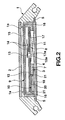
- FIG. 2 is an enlarged cross-sectional view taken along II-II of FIG. 1.
- the electronic wristwatch has a case 1 over which as shown in FIG. 2, a crystal 2 is provided.
- a timepiece module 3 is housed within the case 1 whose lower end is closed with a back cover 4 through a waterproof ring 5.
- a plurality of push button switches 6 are provided on the case 1 at three and nine o'clock.
- the timepiece module 3 comprises a time-display hand unit 8, a first liquid crystal display unit 9 and a second liquid crystal display unit 10 housed within a generally shell- or box-like housing 7. More particularly, the time-display hand unit 8 comprises an analog movement 11 provided within the housing 7 and a dial plate 12 provided on the open upper end of the housing 7. A hand shaft 13 of the analog movement 11 extends upward through a hole 12a in the dial plate 12 with the shaft 13 having hands (hour, minute and second hands) 14 on its top such that the hands 14 sweep above the dial plate 12 to thereby indicate time.
- the dial plate 12 is made of transparent or translucent plastic with the hour numerals disposed at substantially equal intervals along a circle.
- the first liquid crystal display unit 9 has a first liquid crystal display panel 15 disposed above the time-display hand unit 8 or the hands 14 and covering substantially the whole area of the dial plate 12.
- the first liquid crystal display panel 15 abuts on its opposite sides on a lower surface of a collar 1a provided on the inner surface of the case 1 and supported by a pair of electrically conductive interconnectors 16 each provided on a respective one of the opposite sides of the housing 7.
- the first liquid crystal display panel 15 comprises a pair of transparent electrode plates (not shown) between which liquid crystal is filled, a pair of polarizer plates (not shown) each provided on a respective one of an upper surface of the upper electrode and a lower surface of the lower electrode.
- a flat electroluminescence element 17 is disposed as a backlight device for the first liquid crystal display panel 15 on a lower surface of the transparent or translucent dial plate 12.
- the electroluminescence element 17 comprises a light source of a flat-surface electroluminescence type with the hand shaft 13 extending through a hole 17a in the electroluminescence element 17.
- the electroluminescence element 17 has a substantially rectangular opening 17b having the same size as, and aligning with, the second liquid crystal display unit 10 (FIG. 1). Light based on the surface electroluminescence passes through the dial plate 12 excluding the hole 17a and the opening 17b to thereby illuminate the lower surface of the first liquid crystal display panel 15.
- the pair of electrically conductive interconnectors 16 extend vertically through the dial plate 12 at opposite positions, respectively, and are at their upper and lower ends in contact with the respective terminals (not shown) of the first liquid crystal display panel 15 and the terminals (not shown) of a circuit board 18 provided on its lower surface provided on a lower end of the housing 7 to thereby electrically connect the first liquid crystal display panel 15 and the circuit board 18.
- the second liquid crystal display unit 10 comprises a second liquid crystal display panel 20 disposed below the dial plate 12 of the time-display hand unit 8, more particularly, below the electroluminescence element 17 that in turn is disposed on a lower surface of the dial plate 12 so as to have the same size as, and aligning with, the opening 17b in the electroluminescence element 17.
- the second liquid crystal display panel 20 is supported at its opposite ends by a pair of electrically conductive interconnectors 21 so as to be in electrical contact with the circuit board 18.
- the second liquid crystal display panel 20 comprises a pair of upper and lower transparent electrode plates (not shown) between which liquid crystal is filled, and a pair of polarizer plates (not shown) each provided on a respective one of an upper surface of the upper electrode plate and a lower surface of the lower electrode plate, and a reflector (not shown) provided on a lower surface of the lower polarizer plate.
- the time-display hand unit 8 is visible through the first liquid crystal display panel 15 and the crystal 2 from outside the case 1, the time indicated by the hands 14 that sweep above the dial plate 12 is visible.
- the plurality of push button switches 6 provided on the side of the case 1 to thereby drive only the second liquid crystal display unit 10
- information such as time is displayed on the second liquid crystal display panel 20, as shown in FIG. 1.
- the second display panel 20 is illuminated with external light, the information displayed on the second display panel 20 can be viewed from outside the case 1 through the opening 17b in the electroluminescence element 17, the dial plate 12, the first liquid crystal display panel 15 and the crystal 2.
- time can be known from the time-display hand unit 8 and the information displayed on the second liquid crystal display panel 20 can be recognized visually.
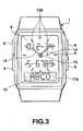
- the electroluminescence element 17 becomes surface-luminous to thereby display information such as time on the whole surface of the first liquid crystal display unit 9, as shown in FIG. 3. Since at this time the light emitted from the surface of the electroluminescence element 17 passes through the dial plate 12 and illuminates the lower surface of the first liquid crystal display panel 15. Thus, the user can view the information displayed on the whole surface of the first liquid crystal display panel 15 through the crystal 2 from outside the case 1. Thus, the user can know time from the time-display hand unit 8 and visually recognize the information displayed on the first liquid crystal display panel 15.
- the electroluminescence element 17 becomes surface-luminous to thereby display different information on the first and second liquid crystal display panels 15 and 20, as shown in FIG. 4.
- the first liquid crystal display panel 15 displays information on the electroluminescence element 17 except for the opening 17b whereas the second liquid crystal display panel 20 displays information different from that displayed by the first liquid crystal display panel 15.
- the first liquid crystal display panel 15 is illuminated with the light from the first liquid crystal display panel 15.
- the user can view the information displayed on the first liquid crystal display panel 15 through the crystal 2 from outside the case 1, as in the above case.
- the second liquid crystal display panel 20 Since at this time the second liquid crystal display panel 20 is illuminated with both the external light and the light emitted by the electroluminescence element 17, the information displayed on the second liquid crystal display panel 20 different from that displayed on the first liquid crystal display panel 15 can be viewed from outside the case 1 through the opening 17b in the electroluminescence element 17, the first liquid crystal display panel 15 and the crystal 2.
- the time can be known from the time-display hand unit 8 and the information displayed on both the first and second liquid crystal display panels 15 and 20 can be viewed well because they do not overlap.
- the first panel 15 of the first liquid crystal display unit 9 is disposed above the time-display hand unit 8, and the second panel 20 of the second liquid crystal display unit 10 is disposed below the time-display hand unit 8.
- the information displayed on the second liquid crystal display panel 20 can be viewed from above through the opening 17a in the electro-luminescence element 17, the dial plate 12, and the first panel 15 of the first liquid crystal display unit 9.
- time can be known from the time-display hand unit 8 and different information displayed on the respective first and second liquid crystal display units 9 and 10 can be viewed.
- the wristwatch that comprises the first and second liquid crystal display units 9 and 10 in addition to the time-display hand unit 8 can display more information to thereby display information on the multiple functions of the timepiece apparatus accordingly.
- FIGS. 5-8 a second embodiment of the electronic wristwatch according to the invention will be described.
- the electronic wristwatch of this embodiment has substantially the same structure as the first embodiment excluding that the dial plate 12 of the time-display hand unit 8 takes the form of a transparent disc with a central circular opening 25, that the second liquid crystal display unit 26 is disposed on a lower surface of the dial plate 12, and that the electroluminescence element 17 is disposed on a lower surface of the second panel 27 of the second liquid crystal display unit 26.
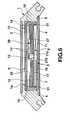
- the second liquid crystal display panel 27 has the same size as the dial plate 12 and is provided on the lower surface of the dial plate 12.
- the second liquid crystal display panel 27 is supported at its opposite ends within the housing 7 by the pair of electrically conductive interconnectors 21 such that the second panel 27 is electrically connected to the circuit board 18.
- the second panel 27 has a transparent construction that comprises a pair of upper and lower transparent electrode plates (not shown) between which liquid crystal is filled, a pair of polarizer plates (not shown) each provided on a respective one of an upper surface of the upper electrode plate and a lower surface of the lower electrode.
- the second panel 27 has a central opening 27a through which the hand shaft 13 extends.
- the display area of the second panel 27 is limited to the one that corresponds to the circular opening 25 in the dial plate 12 and its other area is always transparent.
- the electroluminescence element 17 takes the form of a disc having substantially the same size as the second liquid crystal display panel 27 and has a central hole 17a through which the hand shaft 13 extends such that the light based on the surface luminescence illuminates the lower surface of the second liquid crystal display panel 27, then passes through the second panel 27 and the dial plate 12 to thereby illuminate the lower surface of the first liquid crystal display panel 15.
- the first panel 15 is arranged such that its display switches between a first display state (FIG. 7) that displays information on the whole area of the dial plate 12 and a second display state (FIG. 8) that displays information on a ring-like area excluding the area corresponding to the opening 25 in the dial plate 12.
- the present time can be recognized by viewing the hands that sweep above the dial plate 12 from outside the case 1 through the first liquid crystal display panel 15 and the crystal 2.
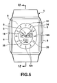
- the electroluminescence element 17 becomes surface-luminous to thereby display information such as time only on the second liquid crystal display panel 27, as shown in FIG. 5.
- the information displayed on the second liquid crystal display panel 27 can be viewed from outside the case 1 through the opening 25 in the dial plate 12, the first liquid crystal display panel 15 and the crystal 2.
- the present time can be known from the time-display hand unit 8 and the information displayed on the second liquid crystal display panel 27 can be recognized visually.
- the electroluminescence element 17 becomes surface-luminous to thereby display information such as time on the first liquid crystal display panel 15, as shown in FIG. 7.
- the first liquid crystal display panel 15 presents the first display state to thereby display information on the whole upper area of the dial plate 12 and the light based on the electroluminescence element 17 passes through the second liquid crystal display panel 27 and the dial plate 12 to thereby illuminate the lower surface of the first liquid crystal display panel 15.
- the information displayed on the first liquid crystal display panel 15 can be viewed from outside the case 1 through the crystal 2.
- time can be known from the time-display hand unit 8 and the information displayed on the first liquid crystal display panel 15 can also be recognized visually.
- the electroluminescence element 17 becomes surface-luminous to thereby display different information on the first and second liquid crystal display panels 15 and 27, respectively, as shown in FIG. 8.
- the first liquid crystal display panel 15 presents the second display state to thereby display information on the ring-like area excluding its area corresponding to the opening area 25 in the dial plate 12 and the second liquid crystal display panel 27 displays information only on its area that corresponds the opening 25 in the dial plate 12.
- the light emitted from the electroluminescence element 17 illuminates the second liquid crystal display panel 27, and then passes through the second liquid crystal display panel 27 and the dial plate 12 to thereby illuminate the lower surface of the first liquid crystal display panel 15.
- the information displayed on the first liquid crystal display panel 15 can be viewed from outside the case 1 through the crystal 2.
- the information displayed on the second liquid crystal display panel 27 can be viewed from outside the case 1 through the opening 25 in the dial plate 12, the first liquid crystal display panel 15, and the crystal 2.
- the information displayed on the first panel 15 does not overlap with the information displayed on the second panel 27, so that time can be known from the time-display hand unit 8 and the different information displayed on the first and second liquid crystal display panels 15 and 17 can be viewed well, respectively.
- time can be known from the time-display hand unit 8 of this electronic wristwatch as in the first embodiment. Further, different information can be displayed on the respective first and second liquid crystal display units 9 and 26.
- the electronic wristwatch of this embodiment is capable of displaying more information by an amount of information displayed by the second liquid crystal display unit 26 to thereby display information on the multiple functions of the timepiece apparatus.
- the first panel 15 switches between its first display state that displays information on the whole upper area of the dial plate 12 and the second display state that displays information on the area of the dial plate 12 excluding its opening 25.
- the first panel 15 displays information on the whole upper area of the dial plate 12 whereas when both the first and second liquid crystal display units 9 and 26 are driven, the first panel 15 displays information on the area of the dial plate 12 excluding its opening 25, so that the information displayed on both the first and second panels 15 and 17 do not overlap to thereby allow the user to view the information well.
- FIGS. 9-12 a third embodiment of the electronic wristwatch according to the present invention will be described.
- This electronic wristwatch has substantially the same structure as the second embodiment excluding that a third liquid crystal display unit 30 is provided on the timepiece module 3 at 6 o'clock. More particularly, the third liquid crystal display unit 30 comprises a third liquid crystal display panel 31 that displays information electro-optically.
- the third panel 31 is disposed within the case 1 at the side of the first panel 15 with being slightly tilted to the surface of the panel 15 and supported at its both ends by the interconnectors 32 so as to be connected electronically to the circuit board 18.
- the third panel 31 has the reflective construction that comprises the pair of upper and lower transparent electrode plates between which liquid crystal is filled, the pair of polarizer plates each provided on the respective one of the upper surface of the upper electrode plates and the lower surface of the lower electrode plates, and the reflector provided on the lower surface of the lower polarize plate such that by applying voltages selectively across the pair of electrode plates, various information such as a telephone number can be displayed on the third panel 31.
- a part of the upper surface of the case 1 is composed of a protective crystal 34 provided above the third panel 31.
- the third panel 31 is illuminated with external light entering through the protective crystal 34 and the displayed information can be viewed from outside the case 1 through the protective crystal 34.
- this wristwatch time can be known from the time-display hand unit 8 and different information can be displayed on both the first and second liquid crystal display units 9 and 26, respectively. Especially, information can also be displayed on the third panel 31 of the third liquid crystal display unit 30 and viewed through the protective crystal 34. Thus, more information can be displayed by an amount of information displayed by the third liquid crystal display unit 30 to thereby display information on the multiple functions of the timepiece apparatus.
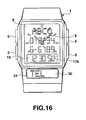
- FIGS. 13-16 a fourth embodiment of the electronic wristwatch according to the present invention will be described.
- the timepiece module 3 comprises the time-display hand unit and the first and second liquid crystal display units 9 and 10. Further, as in the third embodiment it has the third liquid crystal display unit 30.
- the second liquid crystal display unit 10 comprises the second reflective-type liquid crystal display panel 20 disposed below the dial plate 12 of the time-display hand unit 8, that is, below the electroluminescence element 17 so as to face its opening 17b.
- the second panel 20 is disposed within the housing 7 and supported at opposite ends by the pair of interconnectors 21 so as to be connected electrically to the circuit board 18.
- the second liquid crystal display unit 10 displays information such as time electro-optically so as to be visible from above through the opening 17b in the electroluminescence element 17, the dial plate 12 and the first liquid crystal display panel 15.
- the third reflective-type liquid crystal display panel 31 which is slightly tiled to the surface of the first liquid crystal display panel 15 is disposed within the case 1 at the side of the first liquid crystal display panel 15 at six o'clock and supported by the pair of inter connectors 32 such that it is electrically connected to the circuit board 18.
- the protective crystal 34 is provided as a part of the upper surface of the case 1 over the third panel 31. Thus, information displayed on the third panel 31 can be viewed from outside the case 1 through the protective crystal 34.
- this electronic wristwatch time can be known from the time-display hand unit 8, and different information can be displayed on both the first and second liquid crystal display units 9 and 10. Further, other information can be displayed on the third panel 31 of the third liquid crystal display unit 30 and this information can be viewed through the protective crystal 34. Thus, as in the third embodiment more information is displayed to thereby display information on the multiple functions of the timepiece apparatus can be displayed compared to the first embodiment.
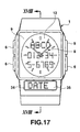
- FIGS. 17 and 18 a fifth embodiment of the electronic wristwatch according to the present invention will be described.
- the first liquid crystal display unit 9 is disposed above the time-display hand unit 8 of the timepiece module 3 and the second liquid crystal display unit 35 is disposed at the side of the first liquid crystal display unit 9 at six o'clock with being slightly tilted to the surface of the first liquid crystal display unit 9.
- the fifth embodiment has the same structure as the first embodiment about the time-display hand unit 8 and the first liquid crystal display unit 9 excluding the second liquid crystal display unit 35.
- the second liquid crystal display unit 35 of the fifth embodiment has a reflective-type second liquid crystal display panel 36 having the same structure as the second liquid crystal display panel 20 of the first embodiment.
- the second liquid crystal display panel 36 is also disposed within the case 1 at the side of the first liquid crystal display panel 15 at six o'clock with being slightly tilted relative to the surface of the first liquid crystal display panel 15 and supported its both ends by the pair of interconnectors 37 so as to be connected electrically to the circuit board 18 to thereby display various information such as a telephone number electro-optically.
- the protective crystal 34 is provided above the second liquid crystal display panel 36 so as to compose a part of the case 1 as in the third embodiment.
- the second panel 36 is illuminated with external light entering through the protective crystal 34 and the displayed information can be viewed from outside the case 1 through the protective crystal 34 to thereby display information on the multiple functions of the timepiece apparatus.
- the first liquid crystal display unit 9 is disposed above the time-display hand unit 8
- the second liquid crystal display unit 35 is disposed at the side of the first liquid crystal display unit 9 with being slightly tilted to the first liquid crystal display panel 15, as described above, such that the information displayed on the second liquid crystal display panel 36 of the second liquid crystal display unit 35 can be viewed from outside the case 1 through the protective crystal 34.
- time can be known from the time-display hand unit 8 and different information displayed on the first and second liquid crystal display units 9 and 35, respectively, can be viewed.
- more information can be displayed by a quantity of information provided by the second liquid crystal display unit 35 compared to the electronic wristwatch in which only the first liquid crystal display unit 9 is provided to display information in addition to the time-display hand unit 8.
- information on the multiple functions of the timepiece apparatus is displayed.
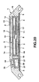
- FIGS. 19-21 a sixth embodiment of the electronic wristwatch according to the invention will be described.
- the electronic wristwatch of this embodiment has substantially the same structure as the fifth embodiment excluding that the dial plate 12 of the time-display hand unit 8 comprises a circular hour marker area 40.
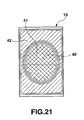
- the first liquid crystal display panel 15 of the first liquid crystal display unit 9 comprises a first display area 41 corresponding to the hour marker area 40 of the dial plate 12 and a second display area 42 corresponding to the area of the dial plate 12 other than its hour marker area 40, in which the first and second display areas 41 and 42 present different display states, respectively.
- the first and second display areas 41 and 42 present positive and negative displays, respectively. More particularly, when no voltages are applied across the pair of transparent electrode plates, the first display area 41 presents an optically transparent state whereas when voltages are applied selectively across the pair of electrodes, the first display area 41 cuts off light to thereby display information only at points thereon to which voltages are applied. When no voltages are applied across the pair of electrode plates, the second display area 42 cuts off light whereas when voltages are applied selectively across the pair of electrode plates, only the points on the second display area 42 to which the voltages are applied allows light to pass therethrough to thereby display corresponding information.
- the second liquid crystal display unit 35 of the sixth embodiment comprises the second reflective-type liquid crystal display panel 36 that is disposed in the housing 7 at the side of the first liquid crystal display panel 15 at six o'clock with being slightly tilted to the surface of the first liquid crystal display panel 15 and supported so as to be electrically connected by the pair of interconnectors 37 to the circuit board 18 to thereby display various information such as a telephone number.
- the protective crystal 34 is provided above the second liquid crystal display panel 36 so as to form a part of the upper surface of the case 1.
- time can be known from the time-display hand unit 8 and different information displayed on both the first and second liquid crystal display units 9 and 35, respectively, can be viewed.
- more information can be displayed.
- the hour marker area 40 is displayed in a brighter state than its outer area because the first display area 41 facing the hour marker area 40 presents the positive display even when the area of the dial plate 12 outside the hour marker area 40 is dark.
- the time indicated by the time-display hand unit 8 is made easier to view.
- FIGS. 22-24 a seventh embodiment of the electronic wristwatch according to the present invention will be described.
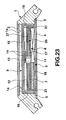
- the first liquid crystal display unit 9 is disposed above the time-display hand unit 8 of the timepiece module 3, and the second liquid crystal display unit 26 is disposed below the time-display hand unit 8.
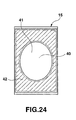
- the first display area 41 facing the hour marker area 40 of the dial plate 12 and the second display area 42 facing the area of the dial plate 12 other than the hour marker area 40 are formed on the first liquid crystal display panel 15 of the first liquid crystal display unit 9.
- the first display area 41 presents a positive display.
- the first display area 41 presents an optically transparent state whereas when voltages are applied selectively across the pair of electrode plates, the first display area 41 cuts off the light at points thereon to which the voltages are applied across the pair of electrode plates to thereby display information.
- the second display area 42 presents a negative display. When no voltages are applied across the pair of electrode plates, the second display area 42 cuts off the light whereas when the voltages are applied across the pair of electrode plates, points on the second display area 42 to which the voltages are applied allow the light to pass therethrough to thereby display information.
- the dial plate 12 is made of transparent or translucent plastic and has a central circular hour marker area 40.
- the second transparent-type liquid crystal display panel 27 is disposed on the whole lower surface of the dial plate 12 within the housing 7 and supported by the pair of inter connectors 21 so as to be electrically connected to the circuit board 18.
- information is displayed only on the area of the second liquid crystal display panel 27 facing the hour marker area 40 of the dial plate 12 and can be viewed from above through the dial plate 12 and the first display area 41 of the first liquid crystal display panel 15.
- this electronic wristwatch time can be known from the time-display hand unit 8 and different information can be displayed on, and viewed from, both the first and second liquid crystal display units 9 and 26.
- more information is displayed to thereby display information on the multiple functions of the timepiece.
- the second display area 42 facing the area of the dial plate 12 other than the hour marker area 40 presents the negative display, so that even when the area of the dial plate 12 other than the hour marker area 40 is dark, the first display area 41 facing the hour marker area 40 presents the positive display.
- the hour marker area 40 of the time-display hand unit 8 is brighter than its outer area.
- the time indicated by the time-display hand unit 8 is made easier to view and the information displayed on the second liquid crystal display panel 27 can be viewed clearly through the first display area 41 of the first liquid crystal display panel 15.
- the present invention is not limited to this arrangement.
- the arrangement may be such that the first display area 45 facing the hour marker area 40 of the dial plate 12 comprises a non-display area that always presents a transparent state and the second display area 46 facing the area of the dial plate 12 other than its hour marker area 40 presents either a positive or a negative display.
- a pair of second electrodes having the same area as, and facing, the first display area 45 may be provided respectively on the opposite surfaces of the first-mentioned pair of electrode plates such that a certain fixed voltage is applied across the pair of second electrodes with the pair of the upper and lower polarizer plates provided respectively on the upper surface of the upper electrode plate and the lower surface of the lower electrode.
- the opposite surface portions of the pair of electrode plates that face the first display area 45 of the first liquid crystal panel 15 may be composed as non-electrode areas such that the first display area 45 has no display functions or always presents a transparent state.
- the pair of electrode plates provided, at least one of the upper and lower polarizer plates may be eliminated to thereby cause the first display area 45 to present a transparent state or carry out no display functions.
- the first display area 45 facing the hour marker area 40 always presents the transparent state.
- the hour marker area 40 is made bright to thereby make the time indicated by the time-display hand unit easier to view.
- the present invention is not limited to these particular cases.
- the present invention is widely applicable to electronic timepiece apparatus such as travel watches, alarm clocks, wall clocks and other clocks.
- the electronic timepiece apparatus of the first to eighth embodiments of FIGS. 1 through 8 comprises the time-display hand unit 8 having hands 14 that sweep above the dial plate 12 thereof; the first liquid crystal display unit 9 disposed above the time-display hand unit for displaying information electro-optically; and the second liquid crystal display unit 10, 26 disposed below the time-display hand unit for displaying information electro-optically.
- the information displayed on the second liquid crystal display unit is visible from above the first liquid crystal display unit through the dial plate and the first liquid crystal display unit.
- the first liquid crystal display unit is disposed above the time-display hand unit and the second liquid crystal display unit is disposed below the time-display hand unit.
- the information displayed on the second liquid crystal display unit is visible through the dial plate and the first liquid crystal display unit.
- the first and second liquid crystal display units can display information, which can be viewed. Therefore, compared to the electronic wristwatch in which only the first liquid crystal display unit displays information, the electronic wristwatch of the present embodiment is capable of displaying much information to thereby display information on the multiple functions thereof.
- the electronic timepiece apparatus of the embodiments of FIGS. 9 through 16 comprises the third liquid crystal display unit 30 disposed substantially flush with the first liquid crystal display unit 9 beside this unit for displaying information electro-optically.
- both the first and second liquid crystal display units are capable of displaying information.
- the third liquid crystal display unit disposed beside the first liquid crystal display unit is also capable of displaying information.
- the apparatus is capable of displaying much more information.
- the electronic timepiece apparatus of the embodiments of FIGS. 17 to 18 comprises the time-display hand unit 8 having hands 14 that sweep above the dial plate 12 thereof; the first liquid crystal display unit 9 disposed above the time-display hand unit for displaying information electro-optically; and the second liquid crystal display unit 35 substantially flush with the first liquid crystal display unit beside this unit for displaying information electro-optically.
- the first liquid crystal display unit disposed above the time-display hand unit is capable of displaying information.
- the second liquid crystal display unit disposed beside the first liquid crystal display unit is capable of displaying information.
- the electronic timepiece apparatus of the embodiments of FIGS. 19 to 26 comprises the time-display hand unit 8 having hands 14 that sweep above the dial plate 12 thereof; and the liquid crystal display unit 9 disposed above the time-display hand unit for displaying information electro-optically, wherein the liquid crystal display unit comprises the first display area 41, 45 that faces the hour marker area of the dial plate and the second display area 42, 46 that faces the area of the dial plate other than the hour marker area, the first and second display areas presenting different display states, respectively.
- the liquid crystal display unit disposed above the time-display hand unit comprises the first display area that faces the hour marker area of the dial plate and the second display area that faces the area of the dial plate other than the hour marker area in which the first and second display areas present different display states.
- the optical permeability of the first display area can be made higher than that of the second display area to thereby made the hour marker area of the dial plate brighter to thereby make the hour marker area brighter.
- the first and second display areas 41, 42 are composed so as to present positive and negative displays, respectively.
- the second display area facing the area of the dial plate other than its hour marker area presents the negative display.
- the area of the dial plate 12 outside the hour marker area is dark.
- the hour marker area is made brighter than its outer area to thereby make the time displayed by the time-display hand unit easier to view.
- the first display area 45 comprises the non-display area that presents the transparent state and the second display area 46 comprises the area that presents any one of positive and negative displays.
- the second display area facing the area of the dial plate other than its hour marker area is composed so as to present either a positive or a negative display state to thereby display information
- the first display area facing the hour marker area always presents the transparent state.
- the hour marker area is made sufficiently bright to make the time indicated by the time-display hand unit easier to view.
Landscapes
- Physics & Mathematics (AREA)
- General Physics & Mathematics (AREA)
- Chemical & Material Sciences (AREA)
- Crystallography & Structural Chemistry (AREA)
- Electromechanical Clocks (AREA)
- Electric Clocks (AREA)
Abstract
Description
- The present invention relates to electronic timepiece apparatus such as electronic wristwatches.
- In a conventional electronic wristwatch, a time-display hand unit whose hands (hour, minute and second hands) sweep around a drive shaft above a dial plate to thereby indicate time and a liquid crystal display panel disposed above the hand unit to electro-optically display numerical information such as time and others are included in a timepiece module case.
- In such an electronic wristwatch, the time-display hand unit is capable of indicating time analogly and the liquid crystal display panel is capable of displaying information such as time digitally. However, since the liquid crystal display panel is merely disposed above the time-display hand unit, the number of items of information that can be displayed on the liquid crystal display panel is limited. That is, a large number of items of information cannot be displayed. For the same reason, when the liquid crystal display panel displays information in its information display area that faces that of the time-display hand unit, the time-display hand unit becomes considerably difficult to view.
- It is an object of the present invention to provide an electronic timepiece apparatus capable of displaying a number of pieces of information to thereby display information on the multiple functions of the apparatus.
- Another object of the present invention is to provide an electronic timepiece apparatus that a user is able to view the time-display hand unit although the liquid crystal display unit is disposed above the time-display hand unit.
- According to an embodiment of the present invention, an electronic timepiece apparatus comprises a time-display hand unit having a dial plate and hands that sweep above the dial plate, a first liquid crystal display unit which is disposed above the time-display hand unit, and a second liquid crystal display unit which is disposed below the time-display hand unit, wherein information displayed on the second liquid crystal display unit is visible from above the first liquid crystal display unit through the dial plate and the first liquid crystal display unit.
- According to another embodiment of the present invention, an electronic timepiece apparatus comprises a time-display hand unit having a dial plate and hands that sweep above the dial plate, a first liquid crystal display unit disposed above the time-display hand unit, and a second liquid crystal display unit which is disposed at a side of the first liquid crystal display unit.
- According to still another embodiment of the present invention, an electronic timepiece apparatus comprises a time-display hand unit having a dial plate and hands that sweep above the dial plate, and a liquid crystal display unit which is disposed above the time-display hand unit and comprises a first display area that faces a first area of the dial plate surrounded by hour markers arranged on the dial plate and a second display area that faces a second area of the dial plate other than the first area, the first and second display areas presenting different display states.
- This summary of the invention does not necessarily describe all necessary features so that the invention may also be a sub-combination of these described features.
- The invention can be more fully understood from the following detailed description when taken in conjunction with the accompanying drawings, in which:
- FIG. 1 is a front view of a first embodiment of an electronic wristwatch according to the invention;
- FIG. 2 is an enlarged cross-sectional view taken along a line II-II of FIG. 1;
- FIG. 3 is a front view of the electronic wristwatch of FIG. 1 when only the first liquid crystal display unit displays information;
- FIG. 4 is a front view of the electronic wristwatch of FIG. 1 when both the first and second liquid crystal display units display information;
- FIG. 5 is a front view of a second embodiment of the electronic wristwatch according to the invention;
- FIG. 6 is an enlarged cross-sectional view taken along a line VI-VI of FIG. 5;
- FIG. 7 is a front view of the electronic wristwatch of FIG. 5 when only the first liquid crystal display unit displays information;
- FIG. 8 is a front view of the electronic wristwatch of FIG. 5 when both the first and second liquid crystal display units display information;
- FIG. 9 is a front view of a third embodiment of an electronic wristwatch according to the invention;
- FIG. 10 is an enlarged cross-sectional view taken along a line X-X of FIG. 9;
- FIG. 11 is a front view of the wristwatch of the third embodiment when the first and third liquid crystal display units display information;
- FIG. 12 is a front view of the wristwatch of the third embodiment when all the first-third liquid crystal display units display information;
- FIG. 13 is a front view of a fourth embodiment of the electronic wristwatch according to the invention;
- FIG. 14 is an enlarged cross-sectional view taken along a line XIV-XIV of FIG. 13;
- FIG. 15 is a front view of the electronic wristwatch of FIG. 13 when the first and third liquid crystal display units display information;
- FIG. 16 is a front view of the electronic wristwatch of FIG. 13 when all the first-third liquid crystal display units display information;
- FIG. 17 is a front view of a fifth embodiment of the electronic wristwatch according to the invention;
- FIG. 18 is an enlarged cross-sectional view taken along a line XVIII-XVIII of FIG. 17;
- FIG. 19 is a front view of a sixth embodiment of the electronic wristwatch according to the invention;
- FIG. 20 is an enlarged cross-sectional view taken along a line XX-XX of FIG. 19;
- FIG. 21 is a plan view of a first and a second display area of a first liquid crystal display panel of FIG. 20;
- FIG. 22 is a front view of a seventh embodiment of the electronic wristwatch according to the invention;
- FIG. 23 is an enlarged cross-sectional view taken along a line XXIII-XXIII of FIG. 22;
- FIG. 24 is a plan view of a first and a second display area of the first liquid crystal display panel of FIG. 23;
- FIG. 25 is a front view of a modification of the electronic wristwatch of the sixth and seventh embodiments shown in FIGS. 19 and 22; and
- FIG. 26 is a plan view of a first and a second display area of the first liquid crystal display panel of FIG. 25.
-
- An embodiment of an electronic wristwatch according to the present invention will now be described with reference to the accompanying drawings.
- Referring to FIGS. 1-4, a first embodiment of the electronic wristwatch as the electronic timepiece apparatus according to the present invention will be described.
- FIG. 1 is a front view of the electronic wristwatch. FIG. 2 is an enlarged cross-sectional view taken along II-II of FIG. 1. The electronic wristwatch has a case 1 over which as shown in FIG. 2, a
crystal 2 is provided. Atimepiece module 3 is housed within the case 1 whose lower end is closed with aback cover 4 through awaterproof ring 5. As shown in FIG. 1, a plurality ofpush button switches 6 are provided on the case 1 at three and nine o'clock. - As shown in FIG. 2, the
timepiece module 3 comprises a time-display hand unit 8, a first liquidcrystal display unit 9 and a second liquidcrystal display unit 10 housed within a generally shell- or box-like housing 7. More particularly, the time-display hand unit 8 comprises ananalog movement 11 provided within thehousing 7 and adial plate 12 provided on the open upper end of thehousing 7. Ahand shaft 13 of theanalog movement 11 extends upward through ahole 12a in thedial plate 12 with theshaft 13 having hands (hour, minute and second hands) 14 on its top such that thehands 14 sweep above thedial plate 12 to thereby indicate time. In this case, thedial plate 12 is made of transparent or translucent plastic with the hour numerals disposed at substantially equal intervals along a circle. - As shown in FIG. 2, the first liquid
crystal display unit 9 has a first liquidcrystal display panel 15 disposed above the time-display hand unit 8 or thehands 14 and covering substantially the whole area of thedial plate 12. The first liquidcrystal display panel 15 abuts on its opposite sides on a lower surface of acollar 1a provided on the inner surface of the case 1 and supported by a pair of electricallyconductive interconnectors 16 each provided on a respective one of the opposite sides of thehousing 7. The first liquidcrystal display panel 15 comprises a pair of transparent electrode plates (not shown) between which liquid crystal is filled, a pair of polarizer plates (not shown) each provided on a respective one of an upper surface of the upper electrode and a lower surface of the lower electrode. By applying voltages across the pair of electrodes selectively, information such as time is displayed electro-optically on thedisplay panel 15. - As shown in FIG. 2, a
flat electroluminescence element 17 is disposed as a backlight device for the first liquidcrystal display panel 15 on a lower surface of the transparent ortranslucent dial plate 12. Theelectroluminescence element 17 comprises a light source of a flat-surface electroluminescence type with thehand shaft 13 extending through ahole 17a in theelectroluminescence element 17. Theelectroluminescence element 17 has a substantiallyrectangular opening 17b having the same size as, and aligning with, the second liquid crystal display unit 10 (FIG. 1). Light based on the surface electroluminescence passes through thedial plate 12 excluding thehole 17a and the opening 17b to thereby illuminate the lower surface of the first liquidcrystal display panel 15. The pair of electricallyconductive interconnectors 16 extend vertically through thedial plate 12 at opposite positions, respectively, and are at their upper and lower ends in contact with the respective terminals (not shown) of the first liquidcrystal display panel 15 and the terminals (not shown) of acircuit board 18 provided on its lower surface provided on a lower end of thehousing 7 to thereby electrically connect the first liquidcrystal display panel 15 and thecircuit board 18. - As shown in FIG. 2, the second liquid
crystal display unit 10 comprises a second liquidcrystal display panel 20 disposed below thedial plate 12 of the time-display hand unit 8, more particularly, below theelectroluminescence element 17 that in turn is disposed on a lower surface of thedial plate 12 so as to have the same size as, and aligning with, the opening 17b in theelectroluminescence element 17. The second liquidcrystal display panel 20 is supported at its opposite ends by a pair of electricallyconductive interconnectors 21 so as to be in electrical contact with thecircuit board 18. Like the first liquidcrystal display panel 15, the second liquidcrystal display panel 20 comprises a pair of upper and lower transparent electrode plates (not shown) between which liquid crystal is filled, and a pair of polarizer plates (not shown) each provided on a respective one of an upper surface of the upper electrode plate and a lower surface of the lower electrode plate, and a reflector (not shown) provided on a lower surface of the lower polarizer plate. Thus, by applying voltages selectively across the pair of electrode plates, information such as time is displayed electro-optically on thesecond display panel 20 and can be viewed from above through the opening 17b in theelectroluminescence element 17, thedial plate 12 and the first liquidcrystal display panel 15. - As shown in FIG. 1, since in this wristwatch the time-
display hand unit 8 is visible through the first liquidcrystal display panel 15 and thecrystal 2 from outside the case 1, the time indicated by thehands 14 that sweep above thedial plate 12 is visible. By operating the plurality of push button switches 6 provided on the side of the case 1 to thereby drive only the second liquidcrystal display unit 10, information such as time is displayed on the second liquidcrystal display panel 20, as shown in FIG. 1. Since at this time thesecond display panel 20 is illuminated with external light, the information displayed on thesecond display panel 20 can be viewed from outside the case 1 through theopening 17b in theelectroluminescence element 17, thedial plate 12, the first liquidcrystal display panel 15 and thecrystal 2. Thus, time can be known from the time-display hand unit 8 and the information displayed on the second liquidcrystal display panel 20 can be recognized visually. - When in this state the plurality of push button switches 6 are appropriately operated to thereby drive the first liquid
crystal display unit 9, theelectroluminescence element 17 becomes surface-luminous to thereby display information such as time on the whole surface of the first liquidcrystal display unit 9, as shown in FIG. 3. Since at this time the light emitted from the surface of theelectroluminescence element 17 passes through thedial plate 12 and illuminates the lower surface of the first liquidcrystal display panel 15. Thus, the user can view the information displayed on the whole surface of the first liquidcrystal display panel 15 through thecrystal 2 from outside the case 1. Thus, the user can know time from the time-display hand unit 8 and visually recognize the information displayed on the first liquidcrystal display panel 15. - Further, when the plurality of push button switches 6 are appropriately operated to thereby drive the first and second liquid
crystal display units electroluminescence element 17 becomes surface-luminous to thereby display different information on the first and second liquidcrystal display panels crystal display panel 15 displays information on theelectroluminescence element 17 except for theopening 17b whereas the second liquidcrystal display panel 20 displays information different from that displayed by the first liquidcrystal display panel 15. In this state, the first liquidcrystal display panel 15 is illuminated with the light from the first liquidcrystal display panel 15. Thus, the user can view the information displayed on the first liquidcrystal display panel 15 through thecrystal 2 from outside the case 1, as in the above case. - Since at this time the second liquid
crystal display panel 20 is illuminated with both the external light and the light emitted by theelectroluminescence element 17, the information displayed on the second liquidcrystal display panel 20 different from that displayed on the first liquidcrystal display panel 15 can be viewed from outside the case 1 through theopening 17b in theelectroluminescence element 17, the first liquidcrystal display panel 15 and thecrystal 2. Thus, the time can be known from the time-display hand unit 8 and the information displayed on both the first and second liquidcrystal display panels - In conclusion, according to this electronic wristwatch the
first panel 15 of the first liquidcrystal display unit 9 is disposed above the time-display hand unit 8, and thesecond panel 20 of the second liquidcrystal display unit 10 is disposed below the time-display hand unit 8. Thus, the information displayed on the second liquidcrystal display panel 20 can be viewed from above through theopening 17a in the electro-luminescence element 17, thedial plate 12, and thefirst panel 15 of the first liquidcrystal display unit 9. Thus, time can be known from the time-display hand unit 8 and different information displayed on the respective first and second liquidcrystal display units crystal display unit 9 in addition to the time-display hand unit 8, the wristwatch that comprises the first and second liquidcrystal display units display hand unit 8 can display more information to thereby display information on the multiple functions of the timepiece apparatus accordingly. - Other embodiments of the electronic wristwatch according to the present invention will be described. The same portions as those of the first embodiment will be indicated in the same reference numerals and their detailed description will be omitted.
- Next, referring to FIGS. 5-8 a second embodiment of the electronic wristwatch according to the invention will be described.
- The electronic wristwatch of this embodiment has substantially the same structure as the first embodiment excluding that the
dial plate 12 of the time-display hand unit 8 takes the form of a transparent disc with a centralcircular opening 25, that the second liquidcrystal display unit 26 is disposed on a lower surface of thedial plate 12, and that theelectroluminescence element 17 is disposed on a lower surface of thesecond panel 27 of the second liquidcrystal display unit 26. - As shown in FIG. 6, the second liquid
crystal display panel 27 has the same size as thedial plate 12 and is provided on the lower surface of thedial plate 12. The second liquidcrystal display panel 27 is supported at its opposite ends within thehousing 7 by the pair of electricallyconductive interconnectors 21 such that thesecond panel 27 is electrically connected to thecircuit board 18. Like the firstliquid crystal panel 15, thesecond panel 27 has a transparent construction that comprises a pair of upper and lower transparent electrode plates (not shown) between which liquid crystal is filled, a pair of polarizer plates (not shown) each provided on a respective one of an upper surface of the upper electrode plate and a lower surface of the lower electrode. Thus, by applying voltages selectively across the pair of electrode plates, information such as time is displayed on thesecond panel 27 electro-optically. - The
second panel 27 has a central opening 27a through which thehand shaft 13 extends. The display area of thesecond panel 27 is limited to the one that corresponds to thecircular opening 25 in thedial plate 12 and its other area is always transparent. Theelectroluminescence element 17 takes the form of a disc having substantially the same size as the second liquidcrystal display panel 27 and has acentral hole 17a through which thehand shaft 13 extends such that the light based on the surface luminescence illuminates the lower surface of the second liquidcrystal display panel 27, then passes through thesecond panel 27 and thedial plate 12 to thereby illuminate the lower surface of the first liquidcrystal display panel 15. Thefirst panel 15 is arranged such that its display switches between a first display state (FIG. 7) that displays information on the whole area of thedial plate 12 and a second display state (FIG. 8) that displays information on a ring-like area excluding the area corresponding to theopening 25 in thedial plate 12. - As in the first embodiment, in this electronic wristwatch the present time can be recognized by viewing the hands that sweep above the
dial plate 12 from outside the case 1 through the first liquidcrystal display panel 15 and thecrystal 2. When the plurality of push button switches 6 are operated appropriately in this state to thereby drive only the second liquidcrystal display unit 26, theelectroluminescence element 17 becomes surface-luminous to thereby display information such as time only on the second liquidcrystal display panel 27, as shown in FIG. 5. Thus, the information displayed on the second liquidcrystal display panel 27 can be viewed from outside the case 1 through theopening 25 in thedial plate 12, the first liquidcrystal display panel 15 and thecrystal 2. As a result, the present time can be known from the time-display hand unit 8 and the information displayed on the second liquidcrystal display panel 27 can be recognized visually. - When the plurality of push button switches 6 are operated appropriately in this state to thereby drive only the first liquid
crystal display unit 9, theelectroluminescence element 17 becomes surface-luminous to thereby display information such as time on the first liquidcrystal display panel 15, as shown in FIG. 7. At this time, the first liquidcrystal display panel 15 presents the first display state to thereby display information on the whole upper area of thedial plate 12 and the light based on theelectroluminescence element 17 passes through the second liquidcrystal display panel 27 and thedial plate 12 to thereby illuminate the lower surface of the first liquidcrystal display panel 15. Thus, as in the first embodiment the information displayed on the first liquidcrystal display panel 15 can be viewed from outside the case 1 through thecrystal 2. Thus, time can be known from the time-display hand unit 8 and the information displayed on the first liquidcrystal display panel 15 can also be recognized visually. - When the plurality of push button switches 6 are also operated appropriately to thereby drive the respective first and second liquid
crystal display units electroluminescence element 17 becomes surface-luminous to thereby display different information on the first and second liquidcrystal display panels crystal display panel 15 presents the second display state to thereby display information on the ring-like area excluding its area corresponding to theopening area 25 in thedial plate 12 and the second liquidcrystal display panel 27 displays information only on its area that corresponds theopening 25 in thedial plate 12. The light emitted from theelectroluminescence element 17 illuminates the second liquidcrystal display panel 27, and then passes through the second liquidcrystal display panel 27 and thedial plate 12 to thereby illuminate the lower surface of the first liquidcrystal display panel 15. - Thus, as shown in FIG. 8 the information displayed on the first liquid
crystal display panel 15 can be viewed from outside the case 1 through thecrystal 2. Further, the information displayed on the second liquidcrystal display panel 27 can be viewed from outside the case 1 through theopening 25 in thedial plate 12, the first liquidcrystal display panel 15, and thecrystal 2. In this case, the information displayed on thefirst panel 15 does not overlap with the information displayed on thesecond panel 27, so that time can be known from the time-display hand unit 8 and the different information displayed on the first and second liquidcrystal display panels - As described above, time can be known from the time-
display hand unit 8 of this electronic wristwatch as in the first embodiment. Further, different information can be displayed on the respective first and second liquidcrystal display units crystal display unit 9 is provided in addition to the time-display hand unit 8, the electronic wristwatch of this embodiment is capable of displaying more information by an amount of information displayed by the second liquidcrystal display unit 26 to thereby display information on the multiple functions of the timepiece apparatus. Especially, thefirst panel 15 switches between its first display state that displays information on the whole upper area of thedial plate 12 and the second display state that displays information on the area of thedial plate 12 excluding itsopening 25. Thus, when only the first liquidcrystal display unit 9 is driven, thefirst panel 15 displays information on the whole upper area of thedial plate 12 whereas when both the first and second liquidcrystal display units first panel 15 displays information on the area of thedial plate 12 excluding itsopening 25, so that the information displayed on both the first andsecond panels - Next, referring to FIGS. 9-12, a third embodiment of the electronic wristwatch according to the present invention will be described.
- This electronic wristwatch has substantially the same structure as the second embodiment excluding that a third liquid
crystal display unit 30 is provided on thetimepiece module 3 at 6 o'clock. More particularly, the third liquidcrystal display unit 30 comprises a third liquidcrystal display panel 31 that displays information electro-optically. Thethird panel 31 is disposed within the case 1 at the side of thefirst panel 15 with being slightly tilted to the surface of thepanel 15 and supported at its both ends by theinterconnectors 32 so as to be connected electronically to thecircuit board 18. - Like the second liquid
crystal display panel 20 of the first embodiment, thethird panel 31 has the reflective construction that comprises the pair of upper and lower transparent electrode plates between which liquid crystal is filled, the pair of polarizer plates each provided on the respective one of the upper surface of the upper electrode plates and the lower surface of the lower electrode plates, and the reflector provided on the lower surface of the lower polarize plate such that by applying voltages selectively across the pair of electrode plates, various information such as a telephone number can be displayed on thethird panel 31. In this case, a part of the upper surface of the case 1 is composed of aprotective crystal 34 provided above thethird panel 31. Thus, thethird panel 31 is illuminated with external light entering through theprotective crystal 34 and the displayed information can be viewed from outside the case 1 through theprotective crystal 34. - As in the second embodiment, in this wristwatch time can be known from the time-
display hand unit 8 and different information can be displayed on both the first and second liquidcrystal display units third panel 31 of the third liquidcrystal display unit 30 and viewed through theprotective crystal 34. Thus, more information can be displayed by an amount of information displayed by the third liquidcrystal display unit 30 to thereby display information on the multiple functions of the timepiece apparatus. - Then, referring to FIGS. 13-16, a fourth embodiment of the electronic wristwatch according to the present invention will be described.
- As in the first embodiment, in this electronic wristwatch of the fourth embodiment the
timepiece module 3 comprises the time-display hand unit and the first and second liquidcrystal display units crystal display unit 30. - As in the first embodiment, the second liquid
crystal display unit 10 comprises the second reflective-type liquidcrystal display panel 20 disposed below thedial plate 12 of the time-display hand unit 8, that is, below theelectroluminescence element 17 so as to face itsopening 17b. Thesecond panel 20 is disposed within thehousing 7 and supported at opposite ends by the pair ofinterconnectors 21 so as to be connected electrically to thecircuit board 18. Thus, the second liquidcrystal display unit 10 displays information such as time electro-optically so as to be visible from above through theopening 17b in theelectroluminescence element 17, thedial plate 12 and the first liquidcrystal display panel 15. - As in the third embodiment, in the third liquid
crystal display unit 30 the third reflective-type liquidcrystal display panel 31 which is slightly tiled to the surface of the first liquidcrystal display panel 15 is disposed within the case 1 at the side of the first liquidcrystal display panel 15 at six o'clock and supported by the pair ofinter connectors 32 such that it is electrically connected to thecircuit board 18. As in the third embodiment, theprotective crystal 34 is provided as a part of the upper surface of the case 1 over thethird panel 31. Thus, information displayed on thethird panel 31 can be viewed from outside the case 1 through theprotective crystal 34. - As in the first embodiment, in this electronic wristwatch time can be known from the time-
display hand unit 8, and different information can be displayed on both the first and second liquidcrystal display units third panel 31 of the third liquidcrystal display unit 30 and this information can be viewed through theprotective crystal 34. Thus, as in the third embodiment more information is displayed to thereby display information on the multiple functions of the timepiece apparatus can be displayed compared to the first embodiment. - Next, referring to FIGS. 17 and 18, a fifth embodiment of the electronic wristwatch according to the present invention will be described.
- In this electronic wristwatch, the first liquid
crystal display unit 9 is disposed above the time-display hand unit 8 of thetimepiece module 3 and the second liquidcrystal display unit 35 is disposed at the side of the first liquidcrystal display unit 9 at six o'clock with being slightly tilted to the surface of the first liquidcrystal display unit 9. More particularly, the fifth embodiment has the same structure as the first embodiment about the time-display hand unit 8 and the first liquidcrystal display unit 9 excluding the second liquidcrystal display unit 35. - The second liquid
crystal display unit 35 of the fifth embodiment has a reflective-type second liquidcrystal display panel 36 having the same structure as the second liquidcrystal display panel 20 of the first embodiment. The second liquidcrystal display panel 36 is also disposed within the case 1 at the side of the first liquidcrystal display panel 15 at six o'clock with being slightly tilted relative to the surface of the first liquidcrystal display panel 15 and supported its both ends by the pair ofinterconnectors 37 so as to be connected electrically to thecircuit board 18 to thereby display various information such as a telephone number electro-optically. In this case, theprotective crystal 34 is provided above the second liquidcrystal display panel 36 so as to compose a part of the case 1 as in the third embodiment. Thus, thesecond panel 36 is illuminated with external light entering through theprotective crystal 34 and the displayed information can be viewed from outside the case 1 through theprotective crystal 34 to thereby display information on the multiple functions of the timepiece apparatus. - As in the first embodiment, in this electronic wristwatch the first liquid
crystal display unit 9 is disposed above the time-display hand unit 8, the second liquidcrystal display unit 35 is disposed at the side of the first liquidcrystal display unit 9 with being slightly tilted to the first liquidcrystal display panel 15, as described above, such that the information displayed on the second liquidcrystal display panel 36 of the second liquidcrystal display unit 35 can be viewed from outside the case 1 through theprotective crystal 34. Thus, time can be known from the time-display hand unit 8 and different information displayed on the first and second liquidcrystal display units crystal display unit 35 compared to the electronic wristwatch in which only the first liquidcrystal display unit 9 is provided to display information in addition to the time-display hand unit 8. Thus, information on the multiple functions of the timepiece apparatus is displayed. - Then, referring to FIGS. 19-21, a sixth embodiment of the electronic wristwatch according to the invention will be described.
- The electronic wristwatch of this embodiment has substantially the same structure as the fifth embodiment excluding that the
dial plate 12 of the time-display hand unit 8 comprises a circularhour marker area 40. The first liquidcrystal display panel 15 of the first liquidcrystal display unit 9 comprises afirst display area 41 corresponding to thehour marker area 40 of thedial plate 12 and asecond display area 42 corresponding to the area of thedial plate 12 other than itshour marker area 40, in which the first andsecond display areas - In the first liquid
crystal display panel 15, the first andsecond display areas first display area 41 presents an optically transparent state whereas when voltages are applied selectively across the pair of electrodes, thefirst display area 41 cuts off light to thereby display information only at points thereon to which voltages are applied. When no voltages are applied across the pair of electrode plates, thesecond display area 42 cuts off light whereas when voltages are applied selectively across the pair of electrode plates, only the points on thesecond display area 42 to which the voltages are applied allows light to pass therethrough to thereby display corresponding information. - As in the fifth embodiment, the second liquid
crystal display unit 35 of the sixth embodiment comprises the second reflective-type liquidcrystal display panel 36 that is disposed in thehousing 7 at the side of the first liquidcrystal display panel 15 at six o'clock with being slightly tilted to the surface of the first liquidcrystal display panel 15 and supported so as to be electrically connected by the pair ofinterconnectors 37 to thecircuit board 18 to thereby display various information such as a telephone number. Also, in this case theprotective crystal 34 is provided above the second liquidcrystal display panel 36 so as to form a part of the upper surface of the case 1. - As in the fifth embodiment, in this electronic wristwatch of the sixth embodiment time can be known from the time-
display hand unit 8 and different information displayed on both the first and second liquidcrystal display units second display area 42 facing the area of thedial plate 12 other than thehour marker area 40 of thedial plate 12 presents the negative display, thehour marker area 40 is displayed in a brighter state than its outer area because thefirst display area 41 facing thehour marker area 40 presents the positive display even when the area of thedial plate 12 outside thehour marker area 40 is dark. Thus, the time indicated by the time-display hand unit 8 is made easier to view. - Next, referring to FIGS. 22-24, a seventh embodiment of the electronic wristwatch according to the present invention will be described.
- As shown in FIG. 23, the first liquid
crystal display unit 9 is disposed above the time-display hand unit 8 of thetimepiece module 3, and the second liquidcrystal display unit 26 is disposed below the time-display hand unit 8. Thefirst display area 41 facing thehour marker area 40 of thedial plate 12 and thesecond display area 42 facing the area of thedial plate 12 other than thehour marker area 40 are formed on the first liquidcrystal display panel 15 of the first liquidcrystal display unit 9. - Also in this case, the
first display area 41 presents a positive display. When no voltages are applied across the pair of transparent electrode plates, thefirst display area 41 presents an optically transparent state whereas when voltages are applied selectively across the pair of electrode plates, thefirst display area 41 cuts off the light at points thereon to which the voltages are applied across the pair of electrode plates to thereby display information. Thesecond display area 42 presents a negative display. When no voltages are applied across the pair of electrode plates, thesecond display area 42 cuts off the light whereas when the voltages are applied across the pair of electrode plates, points on thesecond display area 42 to which the voltages are applied allow the light to pass therethrough to thereby display information. - Like the sixth embodiment, the
dial plate 12 is made of transparent or translucent plastic and has a central circularhour marker area 40. As in the second embodiment, in the second liquidcrystal display unit 26 the second transparent-type liquidcrystal display panel 27 is disposed on the whole lower surface of thedial plate 12 within thehousing 7 and supported by the pair ofinter connectors 21 so as to be electrically connected to thecircuit board 18. Thus, information is displayed only on the area of the second liquidcrystal display panel 27 facing thehour marker area 40 of thedial plate 12 and can be viewed from above through thedial plate 12 and thefirst display area 41 of the first liquidcrystal display panel 15. - Like the sixth embodiment, in this electronic wristwatch time can be known from the time-
display hand unit 8 and different information can be displayed on, and viewed from, both the first and second liquidcrystal display units second display area 42 facing the area of thedial plate 12 other than thehour marker area 40 presents the negative display, so that even when the area of thedial plate 12 other than thehour marker area 40 is dark, thefirst display area 41 facing thehour marker area 40 presents the positive display. Thus, thehour marker area 40 of the time-display hand unit 8 is brighter than its outer area. Thus, the time indicated by the time-display hand unit 8 is made easier to view and the information displayed on the second liquidcrystal display panel 27 can be viewed clearly through thefirst display area 41 of the first liquidcrystal display panel 15. - While in the sixth and seventh embodiments the
first display area 41 that presents the positive display is provided in the first liquidcrystal display panel 15 so as to face thehour marker area 40 of thedial plate 12 and thesecond display area 42 that presents the negative display is provided in the first liquidcrystal display panel 15 so as to face the area of thedial plate 12 other than thehour marker area 40, the present invention is not limited to this arrangement. For example, as shown in FIGS. 25 and 26, the arrangement may be such that thefirst display area 45 facing thehour marker area 40 of thedial plate 12 comprises a non-display area that always presents a transparent state and thesecond display area 46 facing the area of thedial plate 12 other than itshour marker area 40 presents either a positive or a negative display. - In order that in this case the
first display area 45 corresponding to thehour marker area 40 of thedial plate 12 always presents a transparent state, a pair of second electrodes having the same area as, and facing, thefirst display area 45 may be provided respectively on the opposite surfaces of the first-mentioned pair of electrode plates such that a certain fixed voltage is applied across the pair of second electrodes with the pair of the upper and lower polarizer plates provided respectively on the upper surface of the upper electrode plate and the lower surface of the lower electrode. Alternatively, the opposite surface portions of the pair of electrode plates that face thefirst display area 45 of the firstliquid crystal panel 15 may be composed as non-electrode areas such that thefirst display area 45 has no display functions or always presents a transparent state. Alternatively, with the pair of electrode plates provided, at least one of the upper and lower polarizer plates may be eliminated to thereby cause thefirst display area 45 to present a transparent state or carry out no display functions. In this composition, even when thesecond display area 46 facing the area of thedial plate 12 other than thehour marker area 40 is constituted so as to present any one of the negative and positive displays to display information, thefirst display area 45 facing thehour marker area 40 always presents the transparent state. Thus, compared to the sixth embodiment thehour marker area 40 is made bright to thereby make the time indicated by the time-display hand unit easier to view. - While in the first to seventh embodiments and their modifications the electronic wristwatches have been illustrated, the present invention is not limited to these particular cases. For example, the present invention is widely applicable to electronic timepiece apparatus such as travel watches, alarm clocks, wall clocks and other clocks.
- As described above, the electronic timepiece apparatus of the first to eighth embodiments of FIGS. 1 through 8 comprises the time-
display hand unit 8 havinghands 14 that sweep above thedial plate 12 thereof; the first liquidcrystal display unit 9 disposed above the time-display hand unit for displaying information electro-optically; and the second liquidcrystal display unit - According to these embodiments, the first liquid crystal display unit is disposed above the time-display hand unit and the second liquid crystal display unit is disposed below the time-display hand unit. The information displayed on the second liquid crystal display unit is visible through the dial plate and the first liquid crystal display unit. Thus, the first and second liquid crystal display units can display information, which can be viewed. Therefore, compared to the electronic wristwatch in which only the first liquid crystal display unit displays information, the electronic wristwatch of the present embodiment is capable of displaying much information to thereby display information on the multiple functions thereof.
- The electronic timepiece apparatus of the embodiments of FIGS. 9 through 16 comprises the third liquid
crystal display unit 30 disposed substantially flush with the first liquidcrystal display unit 9 beside this unit for displaying information electro-optically. - According to these embodiments, both the first and second liquid crystal display units are capable of displaying information. In addition, the third liquid crystal display unit disposed beside the first liquid crystal display unit is also capable of displaying information. Thus, the apparatus is capable of displaying much more information.
- The electronic timepiece apparatus of the embodiments of FIGS. 17 to 18 comprises the time-
display hand unit 8 havinghands 14 that sweep above thedial plate 12 thereof; the first liquidcrystal display unit 9 disposed above the time-display hand unit for displaying information electro-optically; and the second liquidcrystal display unit 35 substantially flush with the first liquid crystal display unit beside this unit for displaying information electro-optically. - According to these embodiments, the first liquid crystal display unit disposed above the time-display hand unit is capable of displaying information. In addition, even the second liquid crystal display unit disposed beside the first liquid crystal display unit is capable of displaying information. Thus, more information is displayed by this embodiment to thereby display information on the multiple functions of the timepiece apparatus compared to the electronic timepiece in which only the first liquid crystal display unit displays information.
- The electronic timepiece apparatus of the embodiments of FIGS. 19 to 26 comprises the time-
display hand unit 8 havinghands 14 that sweep above thedial plate 12 thereof; and the liquidcrystal display unit 9 disposed above the time-display hand unit for displaying information electro-optically, wherein the liquid crystal display unit comprises thefirst display area second display area - According to these embodiments, the liquid crystal display unit disposed above the time-display hand unit comprises the first display area that faces the hour marker area of the dial plate and the second display area that faces the area of the dial plate other than the hour marker area in which the first and second display areas present different display states. Thus, the optical permeability of the first display area can be made higher than that of the second display area to thereby made the hour marker area of the dial plate brighter to thereby make the hour marker area brighter. Thus, even when the liquid crystal display unit is disposed above the time-display hand unit, the time indicated by the time-display hand unit can be viewed well.
- In the electronic timepiece apparatus of the embodiments of FIGS. 19 through 24, the first and
second display areas - According to these embodiments, the second display area facing the area of the dial plate other than its hour marker area presents the negative display. Thus, the area of the
dial plate 12 outside the hour marker area is dark. However, since the first display area facing the hour marker area presents the positive display, the hour marker area is made brighter than its outer area to thereby make the time displayed by the time-display hand unit easier to view. - In the electronic timepiece apparatus of the embodiments of FIGS. 25 and 26, the
first display area 45 comprises the non-display area that presents the transparent state and thesecond display area 46 comprises the area that presents any one of positive and negative displays. - According to these embodiments, even when the second display area facing the area of the dial plate other than its hour marker area is composed so as to present either a positive or a negative display state to thereby display information, the first display area facing the hour marker area always presents the transparent state. Thus, the hour marker area is made sufficiently bright to make the time indicated by the time-display hand unit easier to view.
- While the description above refers to particular embodiments of the present invention, it will be understood that many modifications may be made without departing from the spirit thereof. The accompanying claims are intended to cover such modifications as would fall within the true scope and spirit of the present invention. The presently disclosed embodiments are therefore to be considered in all respects as illustrative and not restrictive, the scope of the invention being indicated by the appended claims, rather than the foregoing description, and all changes that come within the meaning and range of equivalency of the claims are therefore intended to be embraced therein.
Claims (6)
- An electronic timepiece apparatus comprising:a time-display hand unit (8) having a dial plate (12) and hands (14) that sweep above the dial plate (12), characterized by further comprising:a first liquid crystal display unit (9) which is disposed above the time-display hand unit (8); anda second liquid crystal display unit (10, 26) which is disposed below the time-display hand unit (8),wherein information displayed on the second liquid crystal display unit (10, 26) is visible from above the first liquid crystal display unit (9) through the dial plate (12) and the first liquid crystal display unit (9).
- The electronic timepiece apparatus according to claim 1, characterized by further comprising a third liquid crystal display unit (30) which is disposed at a side of the first liquid crystal display unit (9).
- An electronic timepiece apparatus comprising:a time-display hand unit (8) having a dial plate (12) and hands (14) that sweep above the dial plate (12), characterized by further comprising:a first liquid crystal display unit (9) disposed above the time-display hand unit (8); anda second liquid crystal display unit (35) which is disposed at a side of the first liquid crystal display unit (8).
- An electronic timepiece apparatus comprising:a time-display hand unit (8) having a dial plate (12) and hands (14) that sweep above the dial plate (12), characterized by further comprising:a liquid crystal display unit (9) which is disposed above the time-display hand unit and comprises a first display area (41, 45) that faces a first area of the dial plate (12) surrounded by hour markers arranged on the dial plate (12) and a second display area (42, 46) that faces a second area of the dial plate (12) other than the first area, the first and second display areas presenting different display states.
- The electronic timepiece apparatus according to claim 4, characterized in that the first and second display areas (41, 42) present positive and negative displays, respectively.
- The electronic timepiece apparatus according to claim 4, characterized in that the first display area (45) comprises a non-display area that presents a transparent state and the second display area (46) comprises an area that presents any one of positive and negative displays.
Applications Claiming Priority (2)
| Application Number | Priority Date | Filing Date | Title |
|---|---|---|---|
| JP2003059650 | 2003-03-06 | ||
| JP2003059650A JP2004271259A (en) | 2003-03-06 | 2003-03-06 | Clock module |
Publications (3)
| Publication Number | Publication Date |
|---|---|
| EP1455250A2 true EP1455250A2 (en) | 2004-09-08 |
| EP1455250A3 EP1455250A3 (en) | 2008-01-16 |
| EP1455250B1 EP1455250B1 (en) | 2013-08-07 |
Family
ID=32821213
Family Applications (1)
| Application Number | Title | Priority Date | Filing Date |
|---|---|---|---|
| EP04004974.4A Expired - Lifetime EP1455250B1 (en) | 2003-03-06 | 2004-03-03 | Electronic timepiece apparatus |
Country Status (6)
| Country | Link |
|---|---|
| US (1) | US20040174774A1 (en) |
| EP (1) | EP1455250B1 (en) |
| JP (1) | JP2004271259A (en) |
| KR (1) | KR100595886B1 (en) |
| CN (1) | CN1527164A (en) |
| TW (1) | TWI245174B (en) |
Cited By (2)
| Publication number | Priority date | Publication date | Assignee | Title |
|---|---|---|---|---|
| GB2544381A (en) * | 2015-09-11 | 2017-05-17 | Lenovo Singapore Pte Ltd | Gauge opacity control |
| US10410402B2 (en) | 2001-10-11 | 2019-09-10 | Pure Depth Limited | Display interposing physical object within a three-dimensional volumetric space |
Families Citing this family (21)
| Publication number | Priority date | Publication date | Assignee | Title |
|---|---|---|---|---|
| US20060171256A1 (en) * | 2005-02-03 | 2006-08-03 | Keith Herbert | Global timepiece with double day/double date rendering |
| US8081964B1 (en) | 2005-03-28 | 2011-12-20 | At&T Mobility Ii Llc | System, method and apparatus for wireless communication between a wireless mobile telecommunications device and a remote wireless display |
| KR100754674B1 (en) * | 2006-03-10 | 2007-09-03 | 삼성전자주식회사 | Method and device for selecting menu in mobile terminal |
| KR100770830B1 (en) * | 2006-05-10 | 2007-10-26 | 삼성전자주식회사 | Watch type mobile terminal |
| JP2010530064A (en) * | 2007-06-15 | 2010-09-02 | アイエスエー スイス エス.エー. | Digital display method in analog watch and analog watch using this method |
| US8045421B2 (en) * | 2008-01-17 | 2011-10-25 | Nike, Inc. | Watch with planar light diffusion channel |
| JP4775749B1 (en) * | 2010-10-02 | 2011-09-21 | 日本テクノ株式会社 | clock |
| CH706065A1 (en) * | 2012-01-23 | 2013-07-31 | Daniel Spadini | Watch having an analog display and digital display. |
| JP5949738B2 (en) * | 2013-12-09 | 2016-07-13 | カシオ計算機株式会社 | Module and clock |
| JP2015150274A (en) * | 2014-02-17 | 2015-08-24 | 株式会社オリンピア | Display device, game machine |
| JP6477046B2 (en) * | 2014-09-05 | 2019-03-06 | 株式会社デンソー | Display device |
| JP6476803B2 (en) * | 2014-09-05 | 2019-03-06 | 株式会社デンソー | Display device |
| KR102018022B1 (en) | 2014-09-05 | 2019-09-03 | 가부시키가이샤 덴소 | Display device |
| TWI578506B (en) * | 2014-11-27 | 2017-04-11 | 原相科技股份有限公司 | Optical detecting module with waterproofing function |
| TWD169770S (en) * | 2014-12-08 | 2015-08-11 | 廣達電腦股份有限公司 | smart watch |
| KR102483379B1 (en) * | 2015-09-21 | 2023-01-02 | 삼성디스플레이 주식회사 | Display device |
| JP6547710B2 (en) | 2016-08-05 | 2019-07-24 | カシオ計算機株式会社 | Module and watch |
| TWI668536B (en) * | 2018-11-12 | 2019-08-11 | 巨擘科技股份有限公司 | Wristwatch device and operating method thereof |
| JP7468024B2 (en) * | 2020-03-18 | 2024-04-16 | Toppanホールディングス株式会社 | clock |
| EP3926414A1 (en) * | 2020-06-17 | 2021-12-22 | ETA SA Manufacture Horlogère Suisse | Display device and related method |
| FR3124445B1 (en) * | 2021-06-29 | 2023-08-04 | Faurecia Interieur Ind | Vehicle display device |
Citations (2)
| Publication number | Priority date | Publication date | Assignee | Title |
|---|---|---|---|---|
| JPS5791480A (en) | 1980-11-28 | 1982-06-07 | Seiko Instr & Electronics Ltd | Timepiece |
| EP1128240A1 (en) | 2000-02-22 | 2001-08-29 | Asulab S.A. | Display unit with inverted contrast comprising two superposed display devices |
Family Cites Families (11)
| Publication number | Priority date | Publication date | Assignee | Title |
|---|---|---|---|---|
| DE2821619C3 (en) * | 1978-05-18 | 1981-05-21 | Gebrüder Junghans GmbH, 7230 Schramberg | Electronic clock with analog display and hands and liquid crystal display unit |
| JPS5554485A (en) * | 1978-10-17 | 1980-04-21 | Seiko Epson Corp | Watch |
| JPS56119880A (en) * | 1980-02-26 | 1981-09-19 | Citizen Watch Co Ltd | Hybrid display multifunctional watch |
| GB2084764A (en) * | 1980-09-22 | 1982-04-15 | Timex Corp | Combination analog/digital timepieces |
| GB2090440A (en) * | 1980-12-16 | 1982-07-07 | Ebauchesfabrik Eta Ag | A watch having an analog display and a digital display |
| CN1083583C (en) * | 1995-08-16 | 2002-04-24 | 卡西欧计算机株式会社 | Electronic meters incorporating luminous devices |
| AU8244498A (en) * | 1997-07-18 | 1999-02-10 | Citizen Watch Co. Ltd. | Watch |
| BR9811738A (en) * | 1997-09-01 | 2000-09-05 | Citizen Watch Co Ltd | Electronic device with display section |
| JPH1195698A (en) * | 1997-09-19 | 1999-04-09 | Casio Comput Co Ltd | Light emitting device, timepiece, electronic device, method of manufacturing light emitting device |
| EP0939331B1 (en) * | 1998-02-27 | 2010-04-14 | Asulab S.A. | Display unit comprising two superposed display devices |
| EP1189095A1 (en) * | 2000-09-14 | 2002-03-20 | Asulab S.A. | Two-colour liquid crystal display unit |
-
2003
- 2003-03-06 JP JP2003059650A patent/JP2004271259A/en not_active Abandoned
-
2004
- 2004-03-02 US US10/792,444 patent/US20040174774A1/en not_active Abandoned
- 2004-03-03 CN CNA2004100078591A patent/CN1527164A/en active Pending
- 2004-03-03 EP EP04004974.4A patent/EP1455250B1/en not_active Expired - Lifetime
- 2004-03-05 KR KR1020040014935A patent/KR100595886B1/en not_active Expired - Lifetime
- 2004-03-05 TW TW093105793A patent/TWI245174B/en not_active IP Right Cessation
Patent Citations (2)
| Publication number | Priority date | Publication date | Assignee | Title |
|---|---|---|---|---|
| JPS5791480A (en) | 1980-11-28 | 1982-06-07 | Seiko Instr & Electronics Ltd | Timepiece |
| EP1128240A1 (en) | 2000-02-22 | 2001-08-29 | Asulab S.A. | Display unit with inverted contrast comprising two superposed display devices |
Cited By (4)
| Publication number | Priority date | Publication date | Assignee | Title |
|---|---|---|---|---|
| US10410402B2 (en) | 2001-10-11 | 2019-09-10 | Pure Depth Limited | Display interposing physical object within a three-dimensional volumetric space |
| GB2544381A (en) * | 2015-09-11 | 2017-05-17 | Lenovo Singapore Pte Ltd | Gauge opacity control |
| US9703268B2 (en) | 2015-09-11 | 2017-07-11 | Lenovo (Singapore) Pte. Ltd. | Gauge opacity control |
| GB2544381B (en) * | 2015-09-11 | 2019-04-24 | Lenovo Singapore Pte Ltd | Gauge opacity control |
Also Published As
| Publication number | Publication date |
|---|---|
| EP1455250B1 (en) | 2013-08-07 |
| EP1455250A3 (en) | 2008-01-16 |
| JP2004271259A (en) | 2004-09-30 |
| KR20040078913A (en) | 2004-09-13 |
| TW200424815A (en) | 2004-11-16 |
| CN1527164A (en) | 2004-09-08 |
| US20040174774A1 (en) | 2004-09-09 |
| TWI245174B (en) | 2005-12-11 |
| KR100595886B1 (en) | 2006-07-03 |
Similar Documents
| Publication | Publication Date | Title |
|---|---|---|
| EP1455250B1 (en) | Electronic timepiece apparatus | |
| US4247930A (en) | Timepiece with hybrid display | |
| US6292439B1 (en) | Watch | |
| US7009915B2 (en) | Compact color changing LCD watch | |
| US6084828A (en) | Timepiece and chronometer with overlapping, separately driven analog and digital displays | |
| WO2000031596A1 (en) | Timepiece | |
| CN1955865A (en) | Display unit with decorative effect for a portable instrument, such as a watch | |
| EP0927907A1 (en) | Liquid crystal display panel | |
| JP2002243878A (en) | Sequential control method for display device equipped with two overlapped display elements | |
| JP2002296375A (en) | Information display device, wristwatch, and portable information apparatus | |
| US20050243653A1 (en) | Electronic device with secondary display projection | |
| WO1997014997A1 (en) | Combination display timepiece equipped with el illumination | |
| EP2455718A1 (en) | Energy meter employing electronic-ink based display | |
| US6181648B1 (en) | Electronic watch equipped with solar cell | |
| JPH0248877B2 (en) | ||
| JPS6138429B2 (en) | ||
| EP1046086B1 (en) | Timepiece and chronometer with overlapping, separately driven analog and digital displays | |
| EP0724180A2 (en) | Liquid crystal display and electronic appliance comprising the same | |
| JPH1164549A (en) | Electronic equipment with solar batteries | |
| JPS6133148B2 (en) | ||
| KR20010052140A (en) | Timepiece and chronometer with overlapping, separately driven analog and digital displays | |
| JPH08146897A (en) | Multiple display device | |
| JP2008151627A (en) | Led display timepiece | |
| JPH0519990U (en) | Electronic clock display structure | |
| KR950024036A (en) | Analog and LCD wristwatches with LED display |
Legal Events
| Date | Code | Title | Description |
|---|---|---|---|
| PUAI | Public reference made under article 153(3) epc to a published international application that has entered the european phase |
Free format text: ORIGINAL CODE: 0009012 |
|
| 17P | Request for examination filed |
Effective date: 20040303 |
|
| AK | Designated contracting states |
Kind code of ref document: A2 Designated state(s): AT BE BG CH CY CZ DE DK EE ES FI FR GB GR HU IE IT LI LU MC NL PL PT RO SE SI SK TR |
|
| AX | Request for extension of the european patent |
Extension state: AL LT LV MK |
|
| PUAL | Search report despatched |
Free format text: ORIGINAL CODE: 0009013 |
|
| AK | Designated contracting states |
Kind code of ref document: A3 Designated state(s): AT BE BG CH CY CZ DE DK EE ES FI FR GB GR HU IE IT LI LU MC NL PL PT RO SE SI SK TR |
|
| AX | Request for extension of the european patent |
Extension state: AL LT LV MK |
|
| AKX | Designation fees paid |
Designated state(s): DE FR GB |
|
| 17Q | First examination report despatched |
Effective date: 20100219 |
|
| GRAP | Despatch of communication of intention to grant a patent |
Free format text: ORIGINAL CODE: EPIDOSNIGR1 |
|
| GRAS | Grant fee paid |
Free format text: ORIGINAL CODE: EPIDOSNIGR3 |
|
| GRAA | (expected) grant |
Free format text: ORIGINAL CODE: 0009210 |
|
| AK | Designated contracting states |
Kind code of ref document: B1 Designated state(s): DE FR GB |
|
| REG | Reference to a national code |
Ref country code: GB Ref legal event code: FG4D |
|
| REG | Reference to a national code |
Ref country code: DE Ref legal event code: R096 Ref document number: 602004042953 Country of ref document: DE Effective date: 20131002 |
|
| PLBE | No opposition filed within time limit |
Free format text: ORIGINAL CODE: 0009261 |
|
| STAA | Information on the status of an ep patent application or granted ep patent |
Free format text: STATUS: NO OPPOSITION FILED WITHIN TIME LIMIT |
|
| 26N | No opposition filed |
Effective date: 20140508 |
|
| REG | Reference to a national code |
Ref country code: DE Ref legal event code: R097 Ref document number: 602004042953 Country of ref document: DE Effective date: 20140508 |
|
| REG | Reference to a national code |
Ref country code: FR Ref legal event code: PLFP Year of fee payment: 13 |
|
| REG | Reference to a national code |
Ref country code: FR Ref legal event code: PLFP Year of fee payment: 14 |
|
| REG | Reference to a national code |
Ref country code: FR Ref legal event code: PLFP Year of fee payment: 15 |
|
| PGFP | Annual fee paid to national office [announced via postgrant information from national office to epo] |
Ref country code: GB Payment date: 20220127 Year of fee payment: 19 Ref country code: DE Payment date: 20220203 Year of fee payment: 19 |
|
| PGFP | Annual fee paid to national office [announced via postgrant information from national office to epo] |
Ref country code: FR Payment date: 20220209 Year of fee payment: 19 |
|
| REG | Reference to a national code |
Ref country code: DE Ref legal event code: R119 Ref document number: 602004042953 Country of ref document: DE |
|
| GBPC | Gb: european patent ceased through non-payment of renewal fee |
Effective date: 20230303 |
|
| PG25 | Lapsed in a contracting state [announced via postgrant information from national office to epo] |
Ref country code: GB Free format text: LAPSE BECAUSE OF NON-PAYMENT OF DUE FEES Effective date: 20230303 |
|
| PG25 | Lapsed in a contracting state [announced via postgrant information from national office to epo] |
Ref country code: GB Free format text: LAPSE BECAUSE OF NON-PAYMENT OF DUE FEES Effective date: 20230303 Ref country code: FR Free format text: LAPSE BECAUSE OF NON-PAYMENT OF DUE FEES Effective date: 20230331 Ref country code: DE Free format text: LAPSE BECAUSE OF NON-PAYMENT OF DUE FEES Effective date: 20231003 |