EP1455173A2 - Roller test bench and procedure for operating such roller test bench - Google Patents
Roller test bench and procedure for operating such roller test bench Download PDFInfo
- Publication number
- EP1455173A2 EP1455173A2 EP03030048A EP03030048A EP1455173A2 EP 1455173 A2 EP1455173 A2 EP 1455173A2 EP 03030048 A EP03030048 A EP 03030048A EP 03030048 A EP03030048 A EP 03030048A EP 1455173 A2 EP1455173 A2 EP 1455173A2
- Authority
- EP
- European Patent Office
- Prior art keywords
- roller
- test bench
- vehicle
- roller test
- speed
- Prior art date
- Legal status (The legal status is an assumption and is not a legal conclusion. Google has not performed a legal analysis and makes no representation as to the accuracy of the status listed.)
- Granted
Links
- 238000000034 method Methods 0.000 title claims abstract description 22
- 238000006243 chemical reaction Methods 0.000 claims abstract description 24
- 238000004088 simulation Methods 0.000 claims abstract description 7
- 230000000284 resting effect Effects 0.000 claims abstract 2
- 230000001133 acceleration Effects 0.000 claims description 17
- 230000033001 locomotion Effects 0.000 description 5
- 230000001105 regulatory effect Effects 0.000 description 3
- 238000005070 sampling Methods 0.000 description 3
- 241001136792 Alle Species 0.000 description 2
- 239000002655 kraft paper Substances 0.000 description 2
- 230000004913 activation Effects 0.000 description 1
- 238000013459 approach Methods 0.000 description 1
- 230000033228 biological regulation Effects 0.000 description 1
- 230000008878 coupling Effects 0.000 description 1
- 238000010168 coupling process Methods 0.000 description 1
- 238000005859 coupling reaction Methods 0.000 description 1
- 230000007423 decrease Effects 0.000 description 1
- 230000003247 decreasing effect Effects 0.000 description 1
- 238000011835 investigation Methods 0.000 description 1
- 238000005096 rolling process Methods 0.000 description 1
- 230000003068 static effect Effects 0.000 description 1
Images
Classifications
-
- G—PHYSICS
- G01—MEASURING; TESTING
- G01M—TESTING STATIC OR DYNAMIC BALANCE OF MACHINES OR STRUCTURES; TESTING OF STRUCTURES OR APPARATUS, NOT OTHERWISE PROVIDED FOR
- G01M17/00—Testing of vehicles
- G01M17/007—Wheeled or endless-tracked vehicles
- G01M17/0072—Wheeled or endless-tracked vehicles the wheels of the vehicle co-operating with rotatable rolls
-
- A—HUMAN NECESSITIES
- A45—HAND OR TRAVELLING ARTICLES
- A45F—TRAVELLING OR CAMP EQUIPMENT: SACKS OR PACKS CARRIED ON THE BODY
- A45F3/00—Travelling or camp articles; Sacks or packs carried on the body
- A45F3/52—Nets affording protection against insects
Definitions
- the invention relates to a method for operating a dynamometer with the features of the preamble of the claim 1.
- the invention further relates to a dynamometer to carry out the procedure.
- Roller test benches are designed as counterparts to tires, which absorb this and a forced movement can follow or generate a movement in the Shape of one or more rotatable rollers or rollers (crown, Double rolls).
- Conveyor belts or on two or more rotating cylinders tensioned, running and self-contained Bands are also a counterpart to a tire trained, which take this and a forced Follow movement or create a movement yourself.
- a first type of drive there are in particular several drives mechanically coupled with each other via rollers with belts.
- the individual drives mechanically via couplings connected.
- the speed change depends the magnitude of the forces on the surface of the wheels and the mechanically installed mass or the moments of inertia all mechanical parts to be set in motion.
- one unit i.e. a drive train that can accommodate a wheel
- a unit or two Units (1 axis) is determined as the master.
- the current speed of the master drive is measured and to the slave drives, if any, as setpoint passed. It can occur that the speeds and the speeds of the four sets of rollers from each other deviate because there is no mechanical connection between the individual Roles and drives exist.
- the invention has for its object a method for Operation of a dynamometer, which is special realistic knowledge about the reaction behavior of a Motor vehicle should convey.
- a roller dynamometer is also to be used be offered for such a procedure.
- the task is performed using a method with the characteristics characterizing part of claim 1 in conjunction with solved the features of the generic term.
- Advantageous versions of the procedure are in the subclaims 2-8.
- reaction forces of all roles can now be added, so that a total reaction force of the roles is determined becomes.
- the target speed in the control loop is based on the determined acceleration is corrected and the individual driven rollers accelerated or braked accordingly, until the target speed is reached or until the reaction forces no acceleration or deceleration request more.
- reaction moments and thus reaction forces can also be used to determine the target speed by accelerating or braking the individual Rolls are constantly brought up to real speed. This is done by a control circuit known per se.
- the exact vehicle mass m is determined when determining the Target speed taken into account.
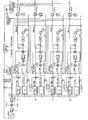
- the invention is based on a circuit example for control of the dynamometer in the drawing figure explained.
- the control consists of four subordinate control loops (for 4 wheels for a motor vehicle with 4 wheels) with which the Speed of each individual roll is regulated. overlapped there is a control loop for this, which is self-guided Operation allows, with the acceleration (accelerating) or Deceleration (braking) of the vehicle to adjust the Roll speed leads.
- the illustrated overlaid control loop (above the dash-dotted Lines) is only active in self-guided mode (also: switched off mode with switch set to v_prüf), which will be explained in more detail later.
- the activation this mode is done by switch 1, which is toggling between v_excellent and v_prüf.
- switch 1 is switched off position shown switched to v_prüf (not shown).
- a vehicle with front-wheel drive is on the test bench.
- the driver engages first gear, engages and Go on. This accelerates on the front wheels Moment exercised.
- the setpoint speed is initially 0 Actual speed increases.
- Build the front electric motors a torque to keep the target speed 0.
- the torque is on within a sampling period the two front rollers converted into the driving force, that would accelerate the vehicle on the road.
- the the resulting acceleration is calculated and the target speed increased accordingly. It turns out Acceleration a the vehicle in the same conditions would experience on the street.
- a mountain trip is simulated in that in the tracked Operation of the slope downforce Ft from the driving force of the Vehicle is withdrawn.
- the engine does not have to accelerate on a flat road exercise, with rolling friction and air resistance initially neglected are.
- Now starts the ascent, in the superimposed control loop adds a positive force so that the total driving force from a physical point of view Vehicle is negative. Therefore, there is a negative acceleration on, the target speed is reduced, the vehicle slows down. To keep the speed, must the driver accelerates. If he does not do this, the vehicle will according to the slope slower.
Landscapes
- Physics & Mathematics (AREA)
- General Physics & Mathematics (AREA)
- Life Sciences & Earth Sciences (AREA)
- Pest Control & Pesticides (AREA)
- Force Measurement Appropriate To Specific Purposes (AREA)
- Electric Propulsion And Braking For Vehicles (AREA)
- Testing Of Engines (AREA)
- Investigating Strength Of Materials By Application Of Mechanical Stress (AREA)
- Testing Of Devices, Machine Parts, Or Other Structures Thereof (AREA)
Abstract
Die Erfindung betrifft ein Verfahren zum Betrieb eines Rollenprüfstandes zur Durchführung von Simulationsfahrten eines auf dem Rollenprüfstand angeordneten Fahrzeugs, wobei mindestens ein Rad des Fahrzeugs auf mindestens einer Rolle des Rollenprüfstandes aufliegt, wobei zur Bestimmung der Sollgeschwindigkeit der Rolle an der Rolle des Rollenprüfstandes ein Reaktionsmoment der Rolle gegenüber dem Rad des Fahrzeugs erfasst wird. Ferner betrifft die Erfindung einen Rollenprüfstand zur Durchführung eines derartigen Verfahrens zum Betrieb eines Rollenprüfstandes. <IMAGE>The invention relates to a method for operating a roller test bench for carrying out simulation runs of a vehicle arranged on the roller test bench, at least one wheel of the vehicle resting on at least one roller of the roller test bench, a reaction moment of the roller being used to determine the desired speed of the roller on the roller of the roller test bench against the wheel of the vehicle is detected. The invention further relates to a roller test bench for performing such a method for operating a roller test bench. <IMAGE>
Description
Die Erfindung betrifft ein Verfahren zum Betrieb eines Rollenprüfstandes mit den Merkmalen des Oberbegriffs des Patentanspruchs 1. Ferner betrifft die Erfindung einen Rollenprüfstand zur Durchführung des Verfahrens.The invention relates to a method for operating a dynamometer with the features of the preamble of the claim 1. The invention further relates to a dynamometer to carry out the procedure.
Als Stand der Technik sind Prüfstände zur Fahrsimulation in mehreren Varianten (Rollenprüfstände, Förderbänder) bekannt. Rollenprüfstände sind als Gegenstück zu einem Reifen ausgebildet, welche diesen aufnehmen und einer erzwungenen Bewegung folgen bzw. selbst eine Bewegung erzeugen können in der Form einer oder mehrerer drehbarer Rollen bzw. Walzen (Scheitel-, Doppelrollen). Förderbänder oder auf zwei oder mehreren drehbaren Zylindern gespannte, laufende und in sich geschlossene Bänder sind ebenfalls als Gegenstück zu einem Reifen ausgebildet, welche diesen aufnehmen und einer erzwungenen Bewegung folgen bzw. selbst eine Bewegung erzeugen.Test stands for driving simulation are state of the art in several variants (roller test benches, conveyor belts) are known. Roller test benches are designed as counterparts to tires, which absorb this and a forced movement can follow or generate a movement in the Shape of one or more rotatable rollers or rollers (crown, Double rolls). Conveyor belts or on two or more rotating cylinders tensioned, running and self-contained Bands are also a counterpart to a tire trained, which take this and a forced Follow movement or create a movement yourself.
Bei einer ersten Antriebsart sind insbesondere mehrere Antriebe untereinander mechanisch über Rollen mit Riemen gekuppelt. Während der Beschleunigung bzw. Verzögerung werden die einzelnen Antriebe über Kupplungen miteinander mechanisch verbunden. Für den Fall, dass das System mittels eines Fahrzeuges beschleunigt wird, hängt die Geschwindig-keitsänderung von der Größe der Kräfte an der Oberfläche der Räder und von der mechanisch installierten Masse bzw. den Trägheitsmomenten sämtlicher in Bewegung zu setzender mechanischer Teile ab.In a first type of drive there are in particular several drives mechanically coupled with each other via rollers with belts. During acceleration or deceleration, the individual drives mechanically via couplings connected. In the event that the system is by means of a vehicle is accelerated, the speed change depends the magnitude of the forces on the surface of the wheels and the mechanically installed mass or the moments of inertia all mechanical parts to be set in motion.
Bei einer weiteren Antriebsart wird jeweils eine Einheit (also ein Antriebsstrang, welcher ein Rad aufnehmen kann) mit einem Elektromotor angetrieben. Es gibt außer in Servicebetriebsarten keine mechanische Verbindung zwischen den Einheiten, falls mehrere vorhanden sind. Eine Einheit oder zwei Einheiten (1 Achse) wird als Master bestimmt. Es besteht die Möglichkeit, dass der Masterantrieb auf ein konstantes Drehmoment (positiv oder negativ- für Ent- oder Belastung) geregelt wird, der Antrieb ist aber nicht drehzahlgeregelt. Die aktuelle Geschwindigkeit des Masterantriebs wird gemessen und an die Slaveantriebe falls welche vorhanden sind als Sollwert weitergegeben. Dabei kann es auftreten, dass die Drehzahlen und die Geschwindigkeiten der vier Rollensätze voneinander abweichen, da keine mechanische Verbindung zwischen den einzelnen Rollen und Antriebe existiert.With another type of drive, one unit (i.e. a drive train that can accommodate a wheel) with driven by an electric motor. There are except in service modes no mechanical connection between the units, if there are several. A unit or two Units (1 axis) is determined as the master. There is Possibility that the master drive to a constant torque (positive or negative - for relief or burden) regulated the drive is not speed-controlled. The current speed of the master drive is measured and to the slave drives, if any, as setpoint passed. It can occur that the speeds and the speeds of the four sets of rollers from each other deviate because there is no mechanical connection between the individual Roles and drives exist.
Der Erfindung liegt die Aufgabe zugrunde, ein Verfahren zum Betrieb eines Rollenprüfstandes anzubieten, welches besonders realitätsnahe Erkenntnisse über das Reaktionsverhalten eines Kraftfahrzeugs vermitteln soll. Ferner soll ein Rollenprüfstand für ein derartiges Verfahren angeboten werden.The invention has for its object a method for Operation of a dynamometer, which is special realistic knowledge about the reaction behavior of a Motor vehicle should convey. A roller dynamometer is also to be used be offered for such a procedure.
Die Aufgabe wird durch ein Verfahren mit den Merkmalen den kennzeichnenden Teils des Patentanspruchs 1 in Verbindung mit den Merkmalen des Oberbegriffs gelöst. Vorteilhafte Ausführungsvarianten des Verfahrens werden in den Unteransprüchen 2 - 8 beschrieben. Für den Rollenprüfstand wird die Aufgabe durch die Merkmale des Patentanspruchs 9 gelöst.The task is performed using a method with the characteristics characterizing part of claim 1 in conjunction with solved the features of the generic term. Advantageous versions of the procedure are in the subclaims 2-8. For the roller dynamometer, the task solved by the features of claim 9.
Beim erfindungsgemäßen Verfahren zum Betrieb eines Rollenprüfstandes zur Durchführung von Simulationsfahrten wird an mindesten einer der Rollen des Rollenprüfstandes das jeweilige Reaktionsmoment der Rollen gegenüber den Rädern des Fahrzeugs (z.B. eines Kraftfahrzeugs oder eines Motorrades) erfasst. Das unter Berücksichtigung der für den Prüfstand selbst als Reibung oder Beschleunigung nötigen Verluste ermittelte Reaktionsmoment wird über den Radius der jeweiligen Rolle in eine Reaktionskraft umgerechnet (Reaktionskraft F = Reaktionsmoment M/ Radius r). Damit wird für die Rolle des Rollenprüfstandes eine Reaktionskraft ermittelt. Diese Ermittlung einer Reaktionskraft sowie die weiteren geschilderten Verfahrensvarianten sind auch analog auf Prüfstände mit Förderbändern anwendbar.In the method according to the invention for operating a dynamometer to carry out simulation runs at least one of the roles of the roller test bench the respective Reaction moment of the roles with the wheels of the Vehicle (e.g. a motor vehicle or a motorcycle) detected. That taking into account that for the test bench losses determined as friction or acceleration Reaction moment is about the radius of each Role converted into a reaction force (reaction force F = Reaction moment M / radius r). This is for the role of Roller dynamometer determined a reaction force. This investigation a reaction force and the others described Process variants are also analog on test benches Conveyor belts applicable.
Die Reaktionskräfte sämtlicher Rollen können nun addiert werden, so dass eine Gesamtreaktionskraft der Rollen ermittelt wird. Ausgehend von der einzelnen Reaktionskraft oder von den aufaddierten Reaktionskräften und der Fahrzeugmasse m wird die Beschleunigung ermittelt, der das Kraftfahrzeug im realen Verkehr auf der Straße ausgesetzt wäre (Beschleunigung a = Reaktionskraft F/Fahrzeugmasse m).The reaction forces of all roles can now be added, so that a total reaction force of the roles is determined becomes. Starting from the individual reaction force or from the added reaction forces and the vehicle mass m the acceleration determined by the motor vehicle in real Traffic on the road would be exposed (acceleration a = Reaction force F / vehicle mass m).
Nun wird im Regelkreislauf die Sollgeschwindigkeit anhand der ermittelten Beschleunigung korrigiert und werden die einzelnen angetriebenen Rollen entsprechend beschleunigt bzw. abgebremst, bis die Sollgeschwindigkeit erreicht wird bzw. bis die Reaktionskräfte keine Beschleunigung oder Verzögerung mehr anfordern.Now the target speed in the control loop is based on the determined acceleration is corrected and the individual driven rollers accelerated or braked accordingly, until the target speed is reached or until the reaction forces no acceleration or deceleration request more.
Bei vorliegenden und ermittelten Reaktionsmomenten und damit auch Reaktionskräften kann damit die ermittelte Sollgeschwindigkeit durch Beschleunigung bzw. Abbremsen der einzelnen Rollen ständig an die reale Geschwindigkeit herangeführt werden. Dies geschieht durch einen an sich bekannten Regelkreislauf.With existing and determined reaction moments and thus reaction forces can also be used to determine the target speed by accelerating or braking the individual Rolls are constantly brought up to real speed. This is done by a control circuit known per se.
Beim erfindungsgemäßen Verfahren können neben den auftretenden Reaktionskräften an den einzelnen Rollen auch weitere Kräfte (z.B. Steigungskräfte, Luftwiderstandskräfte) in die Addition der Reaktionskräfte einbezogen und hierdurch eine erhöhte bzw. entsprechend erniedrigte Beschleunigung ermittelt werden, so dass eine erhöhte bzw. erniedrigte Sollgeschwindigkeit ermittelt wird. Hierdurch werden die Möglichkeiten der Simulation realitätsnäher.In the method according to the invention, in addition to those that occur Reaction forces on the individual roles also others Forces (e.g. gradient forces, drag forces) into the Addition of the reaction forces and thereby a increased or correspondingly reduced acceleration determined be, so that an increased or decreased target speed is determined. This will open up the possibilities the simulation closer to reality.
Ferner wird die exakte Fahrzeugmasse m bei der Ermittlung der Sollgeschwindigkeit berücksichtigt. Furthermore, the exact vehicle mass m is determined when determining the Target speed taken into account.
Die Erfindung ist anhand eines Schaltungsbeispiels zur Regelung des Rollenprüfstandes in der Zeichnungsfigur näher erläutert.The invention is based on a circuit example for control of the dynamometer in the drawing figure explained.
Die Regelung besteht aus vier unterlagerten Regelkreisen (für 4 Rollen für ein Kraftfahrzeug mit 4 Rädern), mit denen die Geschwindigkeit jeder einzelnen Rolle geregelt wird. Überlagert dazu gibt es einen Regelkreis, der einen selbstgeführten Betrieb ermöglicht, wobei die Beschleunigung (Gas geben) oder Verzögerung (Bremsen) des Fahrzeuges zu einer Anpassung der Rollengeschwindigkeit führt.The control consists of four subordinate control loops (for 4 wheels for a motor vehicle with 4 wheels) with which the Speed of each individual roll is regulated. overlapped there is a control loop for this, which is self-guided Operation allows, with the acceleration (accelerating) or Deceleration (braking) of the vehicle to adjust the Roll speed leads.
Die vier unterlagerten Regelkreise werden in der Zeichnungsfigur
durch strichpunktierte Linien markiert. Die Funktion
lässt sich am einfachsten wie folgt beschreiben, wobei die
Erläuterungen bei v_soll beginnen:
Der abgebildete überlagerte Regelkreis (oberhalb der strichpunktierten Linien) ist nur im selbstgeführten Modus aktiv (auch: abgeschalteter Modus mit Schalterstellung auf v_prüf), der später genauer erläutert werden wird. Die Aktivierung dieses Modus erfolgt durch den Schalter 1, der das Umschalten zwischen v_geführt und v_prüf ermöglicht.The illustrated overlaid control loop (above the dash-dotted Lines) is only active in self-guided mode (also: switched off mode with switch set to v_prüf), which will be explained in more detail later. The activation this mode is done by switch 1, which is toggling between v_führer and v_prüf.
In der eingezeichneten Stellung ist der Modus aktiv. Im Ergebnis
werden die Momente aller Rollen addiert und die Beschleunigung
simuliert, die das Fahrzeug auf der Straße erfahren
würde. Die Geschwindigkeit v_soll wird dann anhand der
Beschleunigung korrigiert und an die unterlagerten Regelkreise
(innerhalb der strichpunktierten Linien)weitergegeben. Im
Einzelnen werden die folgenden Schritte durchlaufen:
Der überlagerte Regelkreis (oberhalb der strichpunktierten Linien) ist abschaltbar, hierzu wird der Schalter 1 aus der abgebildeten Stellung umgeschaltet auf v_prüf (nicht abgebildet).The superimposed control loop (above the dash-dotted Lines) can be switched off, for this purpose switch 1 is switched off position shown switched to v_prüf (not shown).
Beim abgeschalteten Modus werden die Geschwindigkeiten der vier Rollen gemäß der Sollgeschwindigkeit geregelt. Ein übergeordneter Rechner gibt eine Fahrkurve mit den sich ändernden Sollgeschwindigkeiten vor. Es gibt keine Rückkopplung der Brems- oder Beschleunigungskräfte auf die Sollgeschwindigkeit. Der Betrieb im abgeschalteten Modus ist für an sich bekannte Tests, nämlich den statischen Bremstest, den Bremstest bei unterschiedlichen Geschwindigkeiten und den ABS-Test vorgesehen.When the mode is switched off, the speeds of the four rollers regulated according to the target speed. A parent Calculator gives a driving curve with the changing Target speeds. There is no feedback from the Braking or acceleration forces to the target speed. Operation in the deactivated mode is known per se Tests, namely the static brake test, the brake test provided at different speeds and the ABS test.
Folgende Tests können mit angeschaltetem Modus durchgeführt werden:The following tests can be carried out with the mode switched on become:
Auf dem Prüfstand befindet sich ein Fahrzeug mit Vorderradantrieb. Der Fahrer legt den ersten Gang ein, kuppelt ein und gibt Gas. Dabei wird auf die Vorderräder ein beschleunigendes Moment ausgeübt. Die Sollgeschwindigkeit ist zunächst 0, die Istgeschwindigkeit nimmt zu. Die vorderen Elektromotoren bauen ein Drehmoment auf, um die Sollgeschwindigkeit 0 zu halten. Innerhalb eines Abtastzeitraums wird das Drehmoment an den beiden vorderen Rollen umgerechnet in die Antriebskraft, mit der das Fahrzeug auf der Straße beschleunigt würde. Die sich einstellende Beschleunigung wird berechnet und die Sollgeschwindigkeit dementsprechend erhöht. Es stellt sich die Beschleunigung ein, die das Fahrzeug bei gleichen Bedingungen auf der Straße erfahren würde.A vehicle with front-wheel drive is on the test bench. The driver engages first gear, engages and Go on. This accelerates on the front wheels Moment exercised. The setpoint speed is initially 0 Actual speed increases. Build the front electric motors a torque to keep the target speed 0. The torque is on within a sampling period the two front rollers converted into the driving force, that would accelerate the vehicle on the road. The the resulting acceleration is calculated and the target speed increased accordingly. It turns out Acceleration a the vehicle in the same conditions would experience on the street.
2. Bremsen aus mittlerer Fahrt (bei Hinterradantrieb) Auf dem Prüfstand befindet sich ein Fahrzeug mit Hinterradantrieb. Die Geschwindigkeit beträgt 50 km/h, der Fahrer hat ausgekuppelt. Betätigt der Fahrer die Bremse, so nimmt die Istgeschwindigkeit zunächst ab. Die Elektromotoren müssen ein beschleunigendes Moment auf die Rollen ausüben, um die Sollgeschwindigkeit wieder zu erreichen. Parallel dazu werden die Bremskräfte aller vier Räder addiert. Aus der Summe der vier Kräfte wird die Verzögerung berechnet, die das Fahrzeug auf der Straße erfahren würde. Die Sollgeschwindigkeit wird dementsprechend verringert und nähert sich der Istgeschwindigkeit an. Die Differenz zwischen Soll- und Istgeschwindigkeit wird also durch die Regelung klein gehalten, indem durch die Rückführung die Sollgeschwindigkeit der Istgeschwindigkeit angepasst wird. Die Verzögerung, die das Fahrzeug in der Realität auf der Straße erfahren würde, wird so simuliert.2. Brakes from medium speed (with rear-wheel drive) A rear-wheel drive vehicle is on the test bench. The speed is 50 km / h, the driver has disengaged. If the driver applies the brake, it takes it Actual speed first. The electric motors must be on exert accelerating moment on the rollers to the target speed to reach again. In parallel, the Braking forces of all four wheels added. From the sum of the four The deceleration that the vehicle is subjected to is calculated the road would experience. The target speed is accordingly decreases and approaches the actual speed on. The difference between target and actual speed is therefore kept small by the regulation by the Feedback the target speed of the actual speed is adjusted. The delay that the vehicle is in reality experienced on the road is simulated.
Eine Bergfahrt wird dadurch simuliert, dass im nachgeführten Betrieb die Hangabtriebskraft Ft von der Antriebskraft des Fahrzeugs abgezogen wird. Bei konstanter Geschwindigkeit auf ebener Straße muss der Motor kein beschleunigendes Moment ausüben, wobei Rollreibung und Luftwiderstand zunächst vernachlässigt seien. Beginnt nun die Bergfahrt, so wird im überlagerten Regelkreis eine positive Kraft addiert, so dass die Gesamtantriebskraft aus physikalischer Sicht auf das Fahrzeug negativ ist. Daher tritt eine negative Beschleunigung auf, die Sollgeschwindigkeit wird verringert, das Fahrzeug wird langsamer. Um die Geschwindigkeit zu halten, muss der Fahrer Gas geben. Tut er dies nicht, so wird das Fahrzeug der Steigung entsprechend langsamer.A mountain trip is simulated in that in the tracked Operation of the slope downforce Ft from the driving force of the Vehicle is withdrawn. At constant speed The engine does not have to accelerate on a flat road exercise, with rolling friction and air resistance initially neglected are. Now starts the ascent, in the superimposed control loop adds a positive force so that the total driving force from a physical point of view Vehicle is negative. Therefore, there is a negative acceleration on, the target speed is reduced, the vehicle slows down. To keep the speed, must the driver accelerates. If he does not do this, the vehicle will according to the slope slower.
Aus den vorstehend genannten Beispielen gehen die Möglichkeiten einer realitätsnahen Simulation durch das beschriebene Verfahren zum Betrieb eines Rollenprüfstandes hervor.The possibilities come from the above examples a realistic simulation by the described Process for operating a dynamometer.
Claims (9)
dadurch gekennzeichnet, dass zur Bestimmung der Sollgeschwindigkeit der Rolle an der Rolle des Rollenprüfstandes ein Reaktionsmoment der Rolle gegenüber dem Rad des Fahrzeugs erfasst wird.Method for operating a roller test bench for carrying out simulation runs of a vehicle arranged on the roller test bench, at least one wheel of the vehicle resting on at least one roller of the roller test bench,
characterized in that a reaction torque of the roller with respect to the wheel of the vehicle is detected to determine the target speed of the roller on the roller of the roller test bench.
Applications Claiming Priority (2)
| Application Number | Priority Date | Filing Date | Title |
|---|---|---|---|
| DE10309247 | 2003-03-03 | ||
| DE10309247 | 2003-03-03 |
Publications (3)
| Publication Number | Publication Date |
|---|---|
| EP1455173A2 true EP1455173A2 (en) | 2004-09-08 |
| EP1455173A3 EP1455173A3 (en) | 2006-02-08 |
| EP1455173B1 EP1455173B1 (en) | 2008-04-23 |
Family
ID=32797790
Family Applications (1)
| Application Number | Title | Priority Date | Filing Date |
|---|---|---|---|
| EP03030048A Expired - Lifetime EP1455173B1 (en) | 2003-03-03 | 2003-12-19 | Roller test bench and procedure for operating such roller test bench |
Country Status (7)
| Country | Link |
|---|---|
| US (1) | US7203602B2 (en) |
| EP (1) | EP1455173B1 (en) |
| KR (1) | KR20040078589A (en) |
| CN (1) | CN100489480C (en) |
| AT (1) | ATE393385T1 (en) |
| DE (1) | DE50309683D1 (en) |
| ES (1) | ES2303883T3 (en) |
Families Citing this family (3)
| Publication number | Priority date | Publication date | Assignee | Title |
|---|---|---|---|---|
| AT11041U3 (en) * | 2009-11-05 | 2010-09-15 | Avl Zoellner Gmbh | METHOD FOR PARAMETRIZING A VEHICLE TEST ROLL FOR VEHICLES |
| US9157833B2 (en) * | 2010-02-10 | 2015-10-13 | Meidensha Corporation | Running-resistance control device |
| US10053078B2 (en) * | 2015-07-30 | 2018-08-21 | Honda Motor Co., Ltd. | Methods, systems, and apparatus to test a vehicle brake system |
Family Cites Families (11)
| Publication number | Priority date | Publication date | Assignee | Title |
|---|---|---|---|---|
| DE2305661C3 (en) * | 1973-02-06 | 1984-12-20 | Robert Bosch Gmbh, 7000 Stuttgart | Roller dynamometer for determining the performance of motor vehicles |
| US4635472A (en) * | 1984-09-13 | 1987-01-13 | The Allen Group Inc. | Chassis dynamometer construction |
| DE3920277C2 (en) * | 1989-06-21 | 1995-06-29 | Licentia Gmbh | Method and device for examining vehicles on test benches |
| US5101660A (en) * | 1991-04-05 | 1992-04-07 | Clayton Industries | Method and apparatus for enabling two or four wheel drive vehicles to be tested under simulated road conditions |
| DE69116143T2 (en) | 1991-06-27 | 1996-05-30 | Meidensha Electric Mfg Co Ltd | Control system for chassis dynamometers to simulate road tests on the car |
| EP1080354A1 (en) * | 1998-05-20 | 2001-03-07 | Her Majesty The Queen in Right of Canada, represented by The Minister of the Environment | Portable roller dynamometer and vehicle testing method |
| DE19900620A1 (en) | 1999-01-11 | 2000-07-13 | Maha Gmbh & Co Kg | Vehicle test bed has drum control stator housings in moving supports and bearings with constant pressure flow oil pockets |
| DE29920168U1 (en) | 1999-11-16 | 2000-03-02 | Marxer, Kurt, 86316 Friedberg | Test bench for motor vehicles |
| WO2002055979A1 (en) * | 2001-01-15 | 2002-07-18 | Siemens Aktiengesellschaft | Road-test simulator |
| DE10120294A1 (en) | 2001-04-25 | 2002-10-31 | Maha Gmbh & Co Kg | Roller dynamometer for motor vehicles |
| DE10207110A1 (en) | 2002-02-20 | 2003-08-28 | Maha Gmbh & Co Kg | Roller dynamometer for motor vehicles |
-
2003
- 2003-12-19 DE DE50309683T patent/DE50309683D1/en not_active Expired - Lifetime
- 2003-12-19 ES ES03030048T patent/ES2303883T3/en not_active Expired - Lifetime
- 2003-12-19 AT AT03030048T patent/ATE393385T1/en active
- 2003-12-19 EP EP03030048A patent/EP1455173B1/en not_active Expired - Lifetime
-
2004
- 2004-02-02 US US10/768,659 patent/US7203602B2/en not_active Expired - Lifetime
- 2004-03-03 KR KR1020040014388A patent/KR20040078589A/en not_active Withdrawn
- 2004-03-03 CN CNB2004100078816A patent/CN100489480C/en not_active Expired - Lifetime
Also Published As
| Publication number | Publication date |
|---|---|
| CN1527041A (en) | 2004-09-08 |
| EP1455173B1 (en) | 2008-04-23 |
| DE50309683D1 (en) | 2008-06-05 |
| US7203602B2 (en) | 2007-04-10 |
| KR20040078589A (en) | 2004-09-10 |
| ES2303883T3 (en) | 2008-09-01 |
| US20040220755A1 (en) | 2004-11-04 |
| EP1455173A3 (en) | 2006-02-08 |
| CN100489480C (en) | 2009-05-20 |
| ATE393385T1 (en) | 2008-05-15 |
Similar Documents
| Publication | Publication Date | Title |
|---|---|---|
| EP3237875B1 (en) | Method and device for performing a test run on a test stand | |
| EP3116734B1 (en) | Method for actuating electric motors in serial hybrid vehicles or fully electric vehicles having at least two separately driven axles | |
| EP3548860B1 (en) | Method for controlling an absorbing dynamometer during a power train test and test bench | |
| EP3172550B1 (en) | Method and test rig for testing a combination of components of a vehicle | |
| DE4103579C2 (en) | ||
| EP0360996B1 (en) | Test bank for motor vehicles, especially for testing the brakes of vehicles provided with an ABS system | |
| DE4142861A1 (en) | METHOD FOR CONTROLLING A DRIVING ROBOT FOR AN AUTOMOBILE | |
| DE10240649A1 (en) | Vehicle Stability Control | |
| EP1037030A2 (en) | Procedure for simulating the behaviour of a vehicle on a roadway | |
| DE102007009860A1 (en) | Method for regulating actual speed of motor vehicle in travel direction during descending incline, involves determining actual speed signal, inclination signal and target-velocity signal | |
| EP2161560A2 (en) | Method for operating a test stand for vehicle power transmissions | |
| EP2681091A1 (en) | Determining wheel and/or axle torque specifications in a motor vehicle | |
| WO2011038429A1 (en) | Method and test stand for simulating the driving behavior of a vehicle | |
| DE3920277C2 (en) | Method and device for examining vehicles on test benches | |
| DE69201776T2 (en) | Motor vehicle braking method and device by controlling the braking torque applied to a wheel. | |
| AT398009B (en) | CONTROL DEVICE FOR A TEST BENCH | |
| EP1455173A2 (en) | Roller test bench and procedure for operating such roller test bench | |
| DE3801647C2 (en) | Method and device for testing a four-wheel drive unit | |
| DE102007015525A1 (en) | Roller dynamometer for single- and multi-axle vehicles with electrical coupling of the drive axles | |
| DE3311543C2 (en) | Method for the dynamic simulation of road driving values on a roller dynamometer | |
| DE1480033A1 (en) | Arrangement for the automatic braking and stopping of vehicles of different masses and variable starting speeds | |
| DE102021207447A1 (en) | Method for operating a brake system of a vehicle | |
| EP2736832B1 (en) | Method for controlling the longitudinal movement of a rail-bound vehicle, curve travel control device and rail-bound vehicle | |
| DE69213417T2 (en) | Motor vehicle deceleration control method | |
| EP3124342A2 (en) | Method for controlling one or more brakes of a vehicle |
Legal Events
| Date | Code | Title | Description |
|---|---|---|---|
| PUAI | Public reference made under article 153(3) epc to a published international application that has entered the european phase |
Free format text: ORIGINAL CODE: 0009012 |
|
| AK | Designated contracting states |
Kind code of ref document: A2 Designated state(s): AT BE BG CH CY CZ DE DK EE ES FI FR GB GR HU IE IT LI LU MC NL PT RO SE SI SK TR |
|
| AX | Request for extension of the european patent |
Extension state: AL LT LV MK |
|
| PUAL | Search report despatched |
Free format text: ORIGINAL CODE: 0009013 |
|
| AK | Designated contracting states |
Kind code of ref document: A3 Designated state(s): AT BE BG CH CY CZ DE DK EE ES FI FR GB GR HU IE IT LI LU MC NL PT RO SE SI SK TR |
|
| AX | Request for extension of the european patent |
Extension state: AL LT LV MK |
|
| 17P | Request for examination filed |
Effective date: 20060724 |
|
| AKX | Designation fees paid |
Designated state(s): AT BE BG CH CY CZ DE DK EE ES FI FR GB GR HU IE IT LI LU MC NL PT RO SE SI SK TR |
|
| 17Q | First examination report despatched |
Effective date: 20060914 |
|
| GRAP | Despatch of communication of intention to grant a patent |
Free format text: ORIGINAL CODE: EPIDOSNIGR1 |
|
| GRAS | Grant fee paid |
Free format text: ORIGINAL CODE: EPIDOSNIGR3 |
|
| GRAA | (expected) grant |
Free format text: ORIGINAL CODE: 0009210 |
|
| AK | Designated contracting states |
Kind code of ref document: B1 Designated state(s): AT BE BG CH CY CZ DE DK EE ES FI FR GB GR HU IE IT LI LU MC NL PT RO SE SI SK TR |
|
| REG | Reference to a national code |
Ref country code: GB Ref legal event code: FG4D Free format text: NOT ENGLISH |
|
| REG | Reference to a national code |
Ref country code: CH Ref legal event code: EP |
|
| REF | Corresponds to: |
Ref document number: 50309683 Country of ref document: DE Date of ref document: 20080605 Kind code of ref document: P |
|
| REG | Reference to a national code |
Ref country code: IE Ref legal event code: FG4D Free format text: LANGUAGE OF EP DOCUMENT: GERMAN |
|
| REG | Reference to a national code |
Ref country code: SE Ref legal event code: TRGR |
|
| REG | Reference to a national code |
Ref country code: ES Ref legal event code: FG2A Ref document number: 2303883 Country of ref document: ES Kind code of ref document: T3 |
|
| PG25 | Lapsed in a contracting state [announced via postgrant information from national office to epo] |
Ref country code: SI Free format text: LAPSE BECAUSE OF FAILURE TO SUBMIT A TRANSLATION OF THE DESCRIPTION OR TO PAY THE FEE WITHIN THE PRESCRIBED TIME-LIMIT Effective date: 20080423 |
|
| NLV1 | Nl: lapsed or annulled due to failure to fulfill the requirements of art. 29p and 29m of the patents act | ||
| PG25 | Lapsed in a contracting state [announced via postgrant information from national office to epo] |
Ref country code: PT Free format text: LAPSE BECAUSE OF FAILURE TO SUBMIT A TRANSLATION OF THE DESCRIPTION OR TO PAY THE FEE WITHIN THE PRESCRIBED TIME-LIMIT Effective date: 20080923 Ref country code: BG Free format text: LAPSE BECAUSE OF FAILURE TO SUBMIT A TRANSLATION OF THE DESCRIPTION OR TO PAY THE FEE WITHIN THE PRESCRIBED TIME-LIMIT Effective date: 20080723 Ref country code: NL Free format text: LAPSE BECAUSE OF FAILURE TO SUBMIT A TRANSLATION OF THE DESCRIPTION OR TO PAY THE FEE WITHIN THE PRESCRIBED TIME-LIMIT Effective date: 20080423 Ref country code: FI Free format text: LAPSE BECAUSE OF FAILURE TO SUBMIT A TRANSLATION OF THE DESCRIPTION OR TO PAY THE FEE WITHIN THE PRESCRIBED TIME-LIMIT Effective date: 20080423 |
|
| REG | Reference to a national code |
Ref country code: IE Ref legal event code: FD4D |
|
| ET | Fr: translation filed | ||
| PG25 | Lapsed in a contracting state [announced via postgrant information from national office to epo] |
Ref country code: DK Free format text: LAPSE BECAUSE OF FAILURE TO SUBMIT A TRANSLATION OF THE DESCRIPTION OR TO PAY THE FEE WITHIN THE PRESCRIBED TIME-LIMIT Effective date: 20080423 Ref country code: IE Free format text: LAPSE BECAUSE OF FAILURE TO SUBMIT A TRANSLATION OF THE DESCRIPTION OR TO PAY THE FEE WITHIN THE PRESCRIBED TIME-LIMIT Effective date: 20080423 |
|
| PG25 | Lapsed in a contracting state [announced via postgrant information from national office to epo] |
Ref country code: RO Free format text: LAPSE BECAUSE OF FAILURE TO SUBMIT A TRANSLATION OF THE DESCRIPTION OR TO PAY THE FEE WITHIN THE PRESCRIBED TIME-LIMIT Effective date: 20080423 Ref country code: SK Free format text: LAPSE BECAUSE OF FAILURE TO SUBMIT A TRANSLATION OF THE DESCRIPTION OR TO PAY THE FEE WITHIN THE PRESCRIBED TIME-LIMIT Effective date: 20080423 |
|
| PLBE | No opposition filed within time limit |
Free format text: ORIGINAL CODE: 0009261 |
|
| STAA | Information on the status of an ep patent application or granted ep patent |
Free format text: STATUS: NO OPPOSITION FILED WITHIN TIME LIMIT |
|
| 26N | No opposition filed |
Effective date: 20090126 |
|
| PG25 | Lapsed in a contracting state [announced via postgrant information from national office to epo] |
Ref country code: EE Free format text: LAPSE BECAUSE OF FAILURE TO SUBMIT A TRANSLATION OF THE DESCRIPTION OR TO PAY THE FEE WITHIN THE PRESCRIBED TIME-LIMIT Effective date: 20080423 |
|
| BERE | Be: lapsed |
Owner name: SIEMENS A.G. Effective date: 20081231 |
|
| PG25 | Lapsed in a contracting state [announced via postgrant information from national office to epo] |
Ref country code: MC Free format text: LAPSE BECAUSE OF NON-PAYMENT OF DUE FEES Effective date: 20081231 |
|
| REG | Reference to a national code |
Ref country code: CH Ref legal event code: PL |
|
| PG25 | Lapsed in a contracting state [announced via postgrant information from national office to epo] |
Ref country code: BE Free format text: LAPSE BECAUSE OF NON-PAYMENT OF DUE FEES Effective date: 20081231 |
|
| PG25 | Lapsed in a contracting state [announced via postgrant information from national office to epo] |
Ref country code: LI Free format text: LAPSE BECAUSE OF NON-PAYMENT OF DUE FEES Effective date: 20081231 Ref country code: CH Free format text: LAPSE BECAUSE OF NON-PAYMENT OF DUE FEES Effective date: 20081231 |
|
| PG25 | Lapsed in a contracting state [announced via postgrant information from national office to epo] |
Ref country code: LU Free format text: LAPSE BECAUSE OF NON-PAYMENT OF DUE FEES Effective date: 20081219 Ref country code: CY Free format text: LAPSE BECAUSE OF FAILURE TO SUBMIT A TRANSLATION OF THE DESCRIPTION OR TO PAY THE FEE WITHIN THE PRESCRIBED TIME-LIMIT Effective date: 20080423 Ref country code: HU Free format text: LAPSE BECAUSE OF FAILURE TO SUBMIT A TRANSLATION OF THE DESCRIPTION OR TO PAY THE FEE WITHIN THE PRESCRIBED TIME-LIMIT Effective date: 20081024 |
|
| PG25 | Lapsed in a contracting state [announced via postgrant information from national office to epo] |
Ref country code: TR Free format text: LAPSE BECAUSE OF FAILURE TO SUBMIT A TRANSLATION OF THE DESCRIPTION OR TO PAY THE FEE WITHIN THE PRESCRIBED TIME-LIMIT Effective date: 20080423 |
|
| PG25 | Lapsed in a contracting state [announced via postgrant information from national office to epo] |
Ref country code: GR Free format text: LAPSE BECAUSE OF FAILURE TO SUBMIT A TRANSLATION OF THE DESCRIPTION OR TO PAY THE FEE WITHIN THE PRESCRIBED TIME-LIMIT Effective date: 20080724 |
|
| PGFP | Annual fee paid to national office [announced via postgrant information from national office to epo] |
Ref country code: AT Payment date: 20101110 Year of fee payment: 8 |
|
| PGFP | Annual fee paid to national office [announced via postgrant information from national office to epo] |
Ref country code: SE Payment date: 20101207 Year of fee payment: 8 |
|
| REG | Reference to a national code |
Ref country code: SE Ref legal event code: EUG |
|
| PG25 | Lapsed in a contracting state [announced via postgrant information from national office to epo] |
Ref country code: SE Free format text: LAPSE BECAUSE OF NON-PAYMENT OF DUE FEES Effective date: 20111220 |
|
| REG | Reference to a national code |
Ref country code: AT Ref legal event code: MM01 Ref document number: 393385 Country of ref document: AT Kind code of ref document: T Effective date: 20111219 |
|
| PG25 | Lapsed in a contracting state [announced via postgrant information from national office to epo] |
Ref country code: AT Free format text: LAPSE BECAUSE OF NON-PAYMENT OF DUE FEES Effective date: 20111219 |
|
| REG | Reference to a national code |
Ref country code: FR Ref legal event code: PLFP Year of fee payment: 13 |
|
| REG | Reference to a national code |
Ref country code: FR Ref legal event code: PLFP Year of fee payment: 14 |
|
| REG | Reference to a national code |
Ref country code: FR Ref legal event code: PLFP Year of fee payment: 15 |
|
| PGFP | Annual fee paid to national office [announced via postgrant information from national office to epo] |
Ref country code: CZ Payment date: 20181218 Year of fee payment: 16 |
|
| PGFP | Annual fee paid to national office [announced via postgrant information from national office to epo] |
Ref country code: FR Payment date: 20190128 Year of fee payment: 17 Ref country code: IT Payment date: 20181220 Year of fee payment: 16 |
|
| PG25 | Lapsed in a contracting state [announced via postgrant information from national office to epo] |
Ref country code: CZ Free format text: LAPSE BECAUSE OF NON-PAYMENT OF DUE FEES Effective date: 20191219 |
|
| PG25 | Lapsed in a contracting state [announced via postgrant information from national office to epo] |
Ref country code: IT Free format text: LAPSE BECAUSE OF NON-PAYMENT OF DUE FEES Effective date: 20191219 Ref country code: FR Free format text: LAPSE BECAUSE OF NON-PAYMENT OF DUE FEES Effective date: 20191231 |
|
| REG | Reference to a national code |
Ref country code: ES Ref legal event code: FD2A Effective date: 20210525 |
|
| PG25 | Lapsed in a contracting state [announced via postgrant information from national office to epo] |
Ref country code: ES Free format text: LAPSE BECAUSE OF NON-PAYMENT OF DUE FEES Effective date: 20191220 |
|
| PGFP | Annual fee paid to national office [announced via postgrant information from national office to epo] |
Ref country code: DE Payment date: 20220620 Year of fee payment: 20 |
|
| PGFP | Annual fee paid to national office [announced via postgrant information from national office to epo] |
Ref country code: GB Payment date: 20230103 Year of fee payment: 20 |
|
| REG | Reference to a national code |
Ref country code: DE Ref legal event code: R071 Ref document number: 50309683 Country of ref document: DE |
|
| REG | Reference to a national code |
Ref country code: GB Ref legal event code: PE20 Expiry date: 20231218 |
|
| PG25 | Lapsed in a contracting state [announced via postgrant information from national office to epo] |
Ref country code: GB Free format text: LAPSE BECAUSE OF EXPIRATION OF PROTECTION Effective date: 20231218 |
|
| PG25 | Lapsed in a contracting state [announced via postgrant information from national office to epo] |
Ref country code: GB Free format text: LAPSE BECAUSE OF EXPIRATION OF PROTECTION Effective date: 20231218 |