EP1455124B1 - Klappenventil - Google Patents
Klappenventil Download PDFInfo
- Publication number
- EP1455124B1 EP1455124B1 EP04005205A EP04005205A EP1455124B1 EP 1455124 B1 EP1455124 B1 EP 1455124B1 EP 04005205 A EP04005205 A EP 04005205A EP 04005205 A EP04005205 A EP 04005205A EP 1455124 B1 EP1455124 B1 EP 1455124B1
- Authority
- EP
- European Patent Office
- Prior art keywords
- disc
- spring leaf
- flow
- flap
- valve according
- Prior art date
- Legal status (The legal status is an assumption and is not a legal conclusion. Google has not performed a legal analysis and makes no representation as to the accuracy of the status listed.)
- Expired - Lifetime
Links
Images

Classifications
-
- F—MECHANICAL ENGINEERING; LIGHTING; HEATING; WEAPONS; BLASTING
- F16—ENGINEERING ELEMENTS AND UNITS; GENERAL MEASURES FOR PRODUCING AND MAINTAINING EFFECTIVE FUNCTIONING OF MACHINES OR INSTALLATIONS; THERMAL INSULATION IN GENERAL
- F16K—VALVES; TAPS; COCKS; ACTUATING-FLOATS; DEVICES FOR VENTING OR AERATING
- F16K1/00—Lift valves or globe valves, i.e. cut-off apparatus with closure members having at least a component of their opening and closing motion perpendicular to the closing faces
- F16K1/16—Lift valves or globe valves, i.e. cut-off apparatus with closure members having at least a component of their opening and closing motion perpendicular to the closing faces with pivoted closure-members
- F16K1/18—Lift valves or globe valves, i.e. cut-off apparatus with closure members having at least a component of their opening and closing motion perpendicular to the closing faces with pivoted closure-members with pivoted discs or flaps
- F16K1/22—Lift valves or globe valves, i.e. cut-off apparatus with closure members having at least a component of their opening and closing motion perpendicular to the closing faces with pivoted closure-members with pivoted discs or flaps with axis of rotation crossing the valve member, e.g. butterfly valves
- F16K1/226—Shaping or arrangements of the sealing
- F16K1/2261—Shaping or arrangements of the sealing the sealing being arranged on the valve member
Definitions
- the invention relates to a valve for shutting off or adjusting the volume flow a gaseous or liquid medium with a flap, the by means of a spindle between an open position and a closed position is pivotable and with a flow body, which has a flow opening limited and has at least one stop edge on which the flap in the closed position rests, the flap a rigid element and a having elastic spring plate, which is resiliently biased and which in the closed position rests sealingly on the stop edge.
- a hinged flap plate has a first rigid Sealing edge and an elastic sealing edge, the latter of a Sheet metal strip is made of spring steel. Flue gas and air ducts have large Diameter and the flap is structurally relatively space consuming.
- Generic fittings are especially in air or gas supply lines used for incinerators.
- valves can with stop Flaps are used. In such fittings the flap is in the Closed position on all sides on a stop edge in the flow body. Of the Swing angle of the flap between the closed position and the open position is about 90 °.
- the object of the invention is accordingly, a fitting as possible to create low leakage flow that is easy to manufacture and assemble is.
- a spring plate takes over by means of bias on both sides of the sealing function. If a temperature-resistant spring plate is used, the fitting is suitable for both hot as well as for cold media. The spring plate takes over as well the function of tolerance, center and angular offset compensation. Thus, at the Assembly no complicated adjustment required.
- the spring plate in the pivoting direction, d. H. on both sides of his Pivot axis has a first and a second flap half, the substantially are semicircular and whose radii are of different sizes ensures that the flap between the open position and the closed position is pivotable.
- the spring plate on the inflow side and the rigid Element arranged downstream Supported in this embodiment the pre-pressure increases the sealing effect.
- the rigid element is designed as a disc.
- the Valve disc supports the spring plate against the deforming effect of flowing medium.
- the cross section of the valve disc substantially corresponds the cross section of the spring plate.
- the disc serves also to bias the spring plate.
- a particularly advantageous development of the invention is that the Spindle in the flow direction spaced from that of the flap and the stop edge formed sealing plane radially through the flow body therethrough to be led. Accordingly, the spindle or the axis of rotation of the runs Flap upstream of or behind the flap, d. H. except for Density level, so that over the entire circumference continuous metallic Sealing surface is generated. Another advantage is that the connection between Spindle and flap do not need to be sealed.
- the spindle is connected to the flap by means of a spacer, especially screwed.
- the spacer extends radially to the Spindle and forms with the flap a substantially right angle.
- the flap with respect to the flow opening by means of centered at least one centering pin in the flap and the spacer is inserted.
- the assembly costs are reduced because an adjustment omitted can.
- the fitting is characterized in that the spring plate at least on one side circumferentially is angled in the direction of the stop edge. By this shaping the sealing effect is further improved. It is enough if the degree of angulation is low.
- it is a fitting for adjusting the combustion air flow in an air duct, not shown, to a combustion device leads.
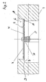
- Fig. 1 shows a view of the valve in the flow direction of the air.
- a Flow body 1 is associated with a flap 2, which by means of a spindle 3 to About 90 ° between an open position and a closed position is pivotable.
- the flap 2 has an elastic spring plate 4 on the inflow side.
- the spring plate 4 has on both sides of its pivot axis a first and a second spring plate half 4a, b, which are substantially semicircular and different Have radii.
- the spring plate 4 between the two Spring plate halves 4a, b each have a slot 5, which ends in a bore 5a.
- the bore 5a is intended to prevent the spring plate 4 from moving the two spring plate halves 4a, b relative to each other, tears.
- FIG. 2 shows that the flow body 1 has a flow opening 6 limited and each in the pivoting to the cross-sectional configuration of the spring plate 4 is adjusted, allowing an unimpeded pivoting movement is possible.
- the flap 2 has downstream a rigid element 7 in the form of a Valve disc on.
- the cross section of the disc 7 is at the cross section adapted to the spring plate 4, wherein the edge region of the spring plate half 4a is not partially covered by the valve disc.
- the spring plate 4 is resiliently biased and is sealing in the closed position on both sides abutment edges 8 in the flow body 1.
- the left spring plate half 4a with the larger radius lies with its top on the stop edge 8 and is from the air against the stop edge 8 pressed. In the closed position of the spindle 3 is a torque transferred to the second flap half 4b. It is sufficient if the Engine stops and closes. The leverage effect enhances the sealing effect. Since the spring plate 4 is arranged on the inflow side, reinforced the form the seal.
- the second spring plate half 4b with the smaller radius is circumferentially in Angled edge region 9 in the direction of the stop edge 8. Through this Shaping the seal is further improved. It is enough if the degree of angulation is relatively low.
- the spindle 3 for pivoting the flap 2 is in the flow direction spaced from the flap 2 in a manner not shown radially through the flow body 1 and is in a known manner with a drive, z. B. connected to an electric motor.
- a drive z. B. connected to an electric motor.
- the flap 2 upstream of between the flap 2 and the stop edge 8 formed sealing plane D is positioned, one over the cross section produced by continuous metallic sealing surface. It is advantageous that the connection between spindle and flap does not have to be sealed.
- Fig. 1 it can be seen that the flap 2 with the spindle 3 by means of a spacer 10, with the flap 2 and the spindle 3 a substantially Angle forms, with the help of two screws 11 is screwed.
- the flap 2 with respect to the flow opening 6 means two centering pins 12 centered in corresponding holes in the flap 2, the spacer 10 and the spindle 3 are inserted.
- the installation effort decreases because an adjustment can be omitted.
Landscapes
- Engineering & Computer Science (AREA)
- General Engineering & Computer Science (AREA)
- Mechanical Engineering (AREA)
- Lift Valve (AREA)
- Compressor (AREA)
- External Artificial Organs (AREA)
Description
- Fig. 1
- eine Ansicht der Armatur in Strömungsrichtung;
- Fig. 2
- einen Schnitt längs der Linie A-A in Fig. 1.
Claims (8)
- Armatur zum Absperren oder Verstellen des Volumenstromes eines gasförmigen oder flüssigen Mediums mit einer Klappe (2), die mittels einer Spindel (3) zwischen einer Offenstellung und einer Schließstellung schwenkbar ist und mit einem Durchflusskörper (1), der eine Durchflussöffnung (6) begrenzt und der mindestens eine Anschlagkante (8) aufweist, auf der die Klappe in der Schließstellung aufliegt, wobei die Klappe (2) ein biegesteifes Element (7) und ein elastisches Federblech (4) aufweist, welches federnd vorgespannt ist und welches in der Schließstellung abdichtend auf der Anschlagkante (8) aufliegt. dadurch gekennzeichnet, dass das Federblech (4) beidseitig entlang seiner Schwenkachse eine erste und eine zweite Federblechhälfte (4a, b) aufweist, die im wesentlichen halbkreisförmig sind und unterschiedliche Radien aufweisen.
- Armatur nach Anspruch 1,
dadurch gekennzeichnet, dass das Federblech (4) anströmseitig und das biegesteife Element (7) abströmseitig angeordnet ist. - Armatur nach Anspruch 1 oder 2,
dadurch gekennzeichnet, dass das biegesteife Element (7) als Klappenscheibe ausgebildet ist. - Armatur nach einem der Ansprüche 1 bis 3,
dadurch gekennzeichnet, dass die Spindel (3) in Strömungsrichtung beabstandet zu der von dem Federblech (4) und der Anschlagkante (8) gebildeten Dichtebene radial durch den Durchflusskörper (1) hindurch geführt wird. - Armatur nach einem der Ansprüche 1 bis 4,
dadurch gekennzeichnet, dass die Spindel (3) mit der Klappe (2) mittels eines Distanzstückes (10) verbunden ist. - Armatur nach einem der Ansprüche 1 bis 5,
dadurch gekennzeichnet, dass die Klappe (2) hinsichtlich der Durchflussöffnung (6) mittels mindestens einem Zentrierstiftes (12) zentriert wird, der in die Klappe (2) und die Spindel (3) und ggf. in das Distanzstück (10) eingesteckt wird. - Armatur nach einem der Ansprüche 1 bis 6,
dadurch gekennzeichnet, dass das Federblech (4) wenigstens einseitig umfangseitig in Richtung auf die Anschlagkante abgewinkelt ist. - Armatur nach einem der Ansprüche 1 bis 7,
dadurch gekennzeichnet, dass das Federblech (4) zwischen den beiden Federblechhälften (4a, b) jeweils einen Schlitz (5) aufweist, der vorzugsweise in einer Bohrung (5a) endet.
Applications Claiming Priority (2)
| Application Number | Priority Date | Filing Date | Title |
|---|---|---|---|
| DE10310039A DE10310039A1 (de) | 2003-03-06 | 2003-03-06 | Armatur zum Absperren oder Verstellen des Volumenstroms eines Mediums |
| DE10310039 | 2003-03-06 |
Publications (2)
| Publication Number | Publication Date |
|---|---|
| EP1455124A1 EP1455124A1 (de) | 2004-09-08 |
| EP1455124B1 true EP1455124B1 (de) | 2005-12-21 |
Family
ID=32797871
Family Applications (1)
| Application Number | Title | Priority Date | Filing Date |
|---|---|---|---|
| EP04005205A Expired - Lifetime EP1455124B1 (de) | 2003-03-06 | 2004-03-04 | Klappenventil |
Country Status (3)
| Country | Link |
|---|---|
| EP (1) | EP1455124B1 (de) |
| AT (1) | ATE313746T1 (de) |
| DE (2) | DE10310039A1 (de) |
Families Citing this family (4)
| Publication number | Priority date | Publication date | Assignee | Title |
|---|---|---|---|---|
| DE102011106744B3 (de) | 2011-06-28 | 2012-12-27 | Pierburg Gmbh | Ventilvorrichtung zur Regelung eines Abgasstroms einer Verbrennungskraftmaschine |
| DE102017101970A1 (de) | 2017-02-01 | 2018-08-02 | GETRAG B.V. & Co. KG | Hydraulikanordnung und Kraftfahrzeugantriebsstrang |
| CN109538803A (zh) * | 2019-01-28 | 2019-03-29 | 佛山市科皓燃烧设备制造有限公司 | 一种低泄漏量的高温蝶阀 |
| CN115183002A (zh) * | 2022-07-24 | 2022-10-14 | 德州华云锦润商贸有限公司 | 一种自锁密封蝶阀 |
Family Cites Families (14)
| Publication number | Priority date | Publication date | Assignee | Title |
|---|---|---|---|---|
| US2846999A (en) * | 1958-08-12 | Flue sealing means for use in conduits | ||
| US3008685A (en) * | 1955-07-07 | 1961-11-14 | Gen Electric | Butterfly valve |
| US3521659A (en) * | 1967-05-18 | 1970-07-28 | Blaw Knox Co | High temperature valve for throttling or three-way application |
| US3620242A (en) * | 1970-01-05 | 1971-11-16 | Babcock & Wilcox Co | Self-cleaning damper assembly |
| US3832940A (en) * | 1973-06-28 | 1974-09-03 | Pacific Air Prod Co | Louver unit having a fire resistant seal |
| AT341848B (de) * | 1974-11-28 | 1978-02-27 | Klinger Ag | Absperrklappe |
| DE2607079A1 (de) * | 1975-03-17 | 1976-09-30 | Exxon Research Engineering Co | Ventil |
| US4077432A (en) * | 1977-01-05 | 1978-03-07 | Mosser Industries, Inc. | Purged valve |
| GB2031119B (en) * | 1978-09-19 | 1983-01-12 | Solent & Pratt | Butterfly valve |
| FR2482236A1 (fr) * | 1980-05-12 | 1981-11-13 | Ramus Laurent | Joint d'etancheite pour vannes, conteneurs ou autres appareillages destines au passage ou au stockage de fluide sous pression |
| JPS57124165A (en) * | 1981-01-24 | 1982-08-02 | Kubota Ltd | Butterfly valve |
| JP3067963B2 (ja) * | 1994-11-01 | 2000-07-24 | 株式会社クボタ | 高温用バタフライ弁のシート構造 |
| JPH1019139A (ja) * | 1996-07-03 | 1998-01-23 | Minolta Co Ltd | 弁体と弁軸との結合構造、この構造を有する弁ユニット、管への弁ユニット及びダブルダンパーの結合構造、並びにこれらを用いたトナーの製造方法 |
| FI4799U1 (fi) * | 2000-11-14 | 2001-01-17 | Sammet Dampers Oy | Savu- ja ilmakanavissa käytettävä sulkupelti |
-
2003
- 2003-03-06 DE DE10310039A patent/DE10310039A1/de not_active Withdrawn
-
2004
- 2004-03-04 AT AT04005205T patent/ATE313746T1/de not_active IP Right Cessation
- 2004-03-04 DE DE502004000190T patent/DE502004000190D1/de not_active Expired - Lifetime
- 2004-03-04 EP EP04005205A patent/EP1455124B1/de not_active Expired - Lifetime
Also Published As
| Publication number | Publication date |
|---|---|
| DE502004000190D1 (de) | 2006-01-26 |
| ATE313746T1 (de) | 2006-01-15 |
| EP1455124A1 (de) | 2004-09-08 |
| DE10310039A1 (de) | 2004-09-16 |
Similar Documents
| Publication | Publication Date | Title |
|---|---|---|
| EP2726719B1 (de) | Ventilvorrichtung zur regelung eines abgasstroms einer verbrennungskraftmaschine | |
| DE102014114968B4 (de) | Regelvorrichtung für eine Verbrennungskraftmaschine | |
| DE102011101948B4 (de) | Verfahren zur Herstellung einer Ventilklappenvorrichtung | |
| EP1771653B1 (de) | Ventil für den einsatz in einer kraftstoffführenden leitung eines kraftfahrzeuges | |
| EP0889269B1 (de) | Regelbarer Kugelhahn | |
| DE102017103834A1 (de) | Sägezahndesign für eine Regelklappe | |
| DE102006043647A1 (de) | Klappenventilanordnung mit verbesserter Strömungscharakteristik | |
| EP1881278B1 (de) | Volumenstromregler | |
| EP1455124A1 (de) | Klappenventil | |
| DE102022101114A1 (de) | Ventilvorrichtung | |
| EP3081788B1 (de) | Auspuffanlage mit einem steuerventil | |
| DE102012224093A1 (de) | Ventilvorrichtung für ein Kraftfahrzeug | |
| DE102007015873A1 (de) | Drosselklappenanordnung | |
| DE102020107769A1 (de) | Regelungsvorrichtung für einen Abgasführungsabschnitt eines Abgasturbolader und Abgasführungsabschnitt für einen Abgasturbolader | |
| DE102012207464A1 (de) | Abgasturbolader für eine Brennkraftmaschine | |
| DE102006025889A1 (de) | Saugkanal für die Verbrennungsluft einer Brennkraftmaschine | |
| DE102019219399B4 (de) | Ventilklappe zur Steuerung eines Fluiddurchflusses durch einen Strömungskanal und Ventil | |
| DE102013103507A1 (de) | Regelvorrichtung für einen Abgasführungsabschnitt einer Turbine | |
| EP4692606A1 (de) | Absperrklappe | |
| DE102004054164B4 (de) | Abgasrückführvorrichtung für eine Verbrennungskraftmaschine | |
| DE202018100009U1 (de) | Absperrklappe | |
| DE202004001919U1 (de) | Absperrvorrichtung für ein Gas führendes Rohr | |
| EP4660496A1 (de) | Selbsttätige rückschlagklappe, funktionsrohr und rohrleitung | |
| EP1832450A1 (de) | Klappenanordnung, insbesondere für ein Kraftfahrzeug | |
| WO2021110204A1 (de) | Industriearmatur-absperreinheit |
Legal Events
| Date | Code | Title | Description |
|---|---|---|---|
| PUAI | Public reference made under article 153(3) epc to a published international application that has entered the european phase |
Free format text: ORIGINAL CODE: 0009012 |
|
| AK | Designated contracting states |
Kind code of ref document: A1 Designated state(s): AT BE BG CH CY CZ DE DK EE ES FI FR GB GR HU IE IT LI LU MC NL PL PT RO SE SI SK TR |
|
| AX | Request for extension of the european patent |
Extension state: AL LT LV MK |
|
| 17P | Request for examination filed |
Effective date: 20040907 |
|
| 17Q | First examination report despatched |
Effective date: 20041213 |
|
| AKX | Designation fees paid |
Designated state(s): AT BE BG CH CY CZ DE DK EE ES FI FR GB GR HU IE IT LI LU MC NL PL PT RO SE SI SK TR |
|
| GRAP | Despatch of communication of intention to grant a patent |
Free format text: ORIGINAL CODE: EPIDOSNIGR1 |
|
| GRAS | Grant fee paid |
Free format text: ORIGINAL CODE: EPIDOSNIGR3 |
|
| GRAA | (expected) grant |
Free format text: ORIGINAL CODE: 0009210 |
|
| AK | Designated contracting states |
Kind code of ref document: B1 Designated state(s): AT BE BG CH CY CZ DE DK EE ES FI FR GB GR HU IE IT LI LU MC NL PL PT RO SE SI SK TR |
|
| PG25 | Lapsed in a contracting state [announced via postgrant information from national office to epo] |
Ref country code: SK Free format text: LAPSE BECAUSE OF FAILURE TO SUBMIT A TRANSLATION OF THE DESCRIPTION OR TO PAY THE FEE WITHIN THE PRESCRIBED TIME-LIMIT Effective date: 20051221 Ref country code: IE Free format text: LAPSE BECAUSE OF FAILURE TO SUBMIT A TRANSLATION OF THE DESCRIPTION OR TO PAY THE FEE WITHIN THE PRESCRIBED TIME-LIMIT Effective date: 20051221 Ref country code: PL Free format text: LAPSE BECAUSE OF FAILURE TO SUBMIT A TRANSLATION OF THE DESCRIPTION OR TO PAY THE FEE WITHIN THE PRESCRIBED TIME-LIMIT Effective date: 20051221 Ref country code: CZ Free format text: LAPSE BECAUSE OF FAILURE TO SUBMIT A TRANSLATION OF THE DESCRIPTION OR TO PAY THE FEE WITHIN THE PRESCRIBED TIME-LIMIT Effective date: 20051221 Ref country code: NL Free format text: LAPSE BECAUSE OF FAILURE TO SUBMIT A TRANSLATION OF THE DESCRIPTION OR TO PAY THE FEE WITHIN THE PRESCRIBED TIME-LIMIT Effective date: 20051221 Ref country code: RO Free format text: LAPSE BECAUSE OF FAILURE TO SUBMIT A TRANSLATION OF THE DESCRIPTION OR TO PAY THE FEE WITHIN THE PRESCRIBED TIME-LIMIT Effective date: 20051221 Ref country code: FI Free format text: LAPSE BECAUSE OF FAILURE TO SUBMIT A TRANSLATION OF THE DESCRIPTION OR TO PAY THE FEE WITHIN THE PRESCRIBED TIME-LIMIT Effective date: 20051221 Ref country code: SI Free format text: LAPSE BECAUSE OF FAILURE TO SUBMIT A TRANSLATION OF THE DESCRIPTION OR TO PAY THE FEE WITHIN THE PRESCRIBED TIME-LIMIT Effective date: 20051221 |
|
| REG | Reference to a national code |
Ref country code: GB Ref legal event code: FG4D Free format text: NOT ENGLISH |
|
| REG | Reference to a national code |
Ref country code: CH Ref legal event code: EP |
|
| REG | Reference to a national code |
Ref country code: IE Ref legal event code: FG4D Free format text: LANGUAGE OF EP DOCUMENT: GERMAN |
|
| REF | Corresponds to: |
Ref document number: 502004000190 Country of ref document: DE Date of ref document: 20060126 Kind code of ref document: P |
|
| PG25 | Lapsed in a contracting state [announced via postgrant information from national office to epo] |
Ref country code: AT Free format text: LAPSE BECAUSE OF NON-PAYMENT OF DUE FEES Effective date: 20060304 |
|
| PG25 | Lapsed in a contracting state [announced via postgrant information from national office to epo] |
Ref country code: SE Free format text: LAPSE BECAUSE OF FAILURE TO SUBMIT A TRANSLATION OF THE DESCRIPTION OR TO PAY THE FEE WITHIN THE PRESCRIBED TIME-LIMIT Effective date: 20060321 Ref country code: BG Free format text: LAPSE BECAUSE OF FAILURE TO SUBMIT A TRANSLATION OF THE DESCRIPTION OR TO PAY THE FEE WITHIN THE PRESCRIBED TIME-LIMIT Effective date: 20060321 Ref country code: GR Free format text: LAPSE BECAUSE OF FAILURE TO SUBMIT A TRANSLATION OF THE DESCRIPTION OR TO PAY THE FEE WITHIN THE PRESCRIBED TIME-LIMIT Effective date: 20060321 Ref country code: DK Free format text: LAPSE BECAUSE OF FAILURE TO SUBMIT A TRANSLATION OF THE DESCRIPTION OR TO PAY THE FEE WITHIN THE PRESCRIBED TIME-LIMIT Effective date: 20060321 |
|
| PG25 | Lapsed in a contracting state [announced via postgrant information from national office to epo] |
Ref country code: MC Free format text: LAPSE BECAUSE OF NON-PAYMENT OF DUE FEES Effective date: 20060331 Ref country code: LU Free format text: LAPSE BECAUSE OF NON-PAYMENT OF DUE FEES Effective date: 20060331 |
|
| PG25 | Lapsed in a contracting state [announced via postgrant information from national office to epo] |
Ref country code: ES Free format text: LAPSE BECAUSE OF FAILURE TO SUBMIT A TRANSLATION OF THE DESCRIPTION OR TO PAY THE FEE WITHIN THE PRESCRIBED TIME-LIMIT Effective date: 20060401 |
|
| GBT | Gb: translation of ep patent filed (gb section 77(6)(a)/1977) |
Effective date: 20060314 |
|
| PG25 | Lapsed in a contracting state [announced via postgrant information from national office to epo] |
Ref country code: PT Free format text: LAPSE BECAUSE OF FAILURE TO SUBMIT A TRANSLATION OF THE DESCRIPTION OR TO PAY THE FEE WITHIN THE PRESCRIBED TIME-LIMIT Effective date: 20060522 |
|
| NLV1 | Nl: lapsed or annulled due to failure to fulfill the requirements of art. 29p and 29m of the patents act | ||
| PG25 | Lapsed in a contracting state [announced via postgrant information from national office to epo] |
Ref country code: HU Free format text: LAPSE BECAUSE OF FAILURE TO SUBMIT A TRANSLATION OF THE DESCRIPTION OR TO PAY THE FEE WITHIN THE PRESCRIBED TIME-LIMIT Effective date: 20060622 |
|
| REG | Reference to a national code |
Ref country code: IE Ref legal event code: FD4D |
|
| ET | Fr: translation filed | ||
| PLBE | No opposition filed within time limit |
Free format text: ORIGINAL CODE: 0009261 |
|
| STAA | Information on the status of an ep patent application or granted ep patent |
Free format text: STATUS: NO OPPOSITION FILED WITHIN TIME LIMIT |
|
| 26N | No opposition filed |
Effective date: 20060922 |
|
| PG25 | Lapsed in a contracting state [announced via postgrant information from national office to epo] |
Ref country code: EE Free format text: LAPSE BECAUSE OF FAILURE TO SUBMIT A TRANSLATION OF THE DESCRIPTION OR TO PAY THE FEE WITHIN THE PRESCRIBED TIME-LIMIT Effective date: 20051221 |
|
| PG25 | Lapsed in a contracting state [announced via postgrant information from national office to epo] |
Ref country code: TR Free format text: LAPSE BECAUSE OF FAILURE TO SUBMIT A TRANSLATION OF THE DESCRIPTION OR TO PAY THE FEE WITHIN THE PRESCRIBED TIME-LIMIT Effective date: 20051221 |
|
| REG | Reference to a national code |
Ref country code: CH Ref legal event code: PL |
|
| PG25 | Lapsed in a contracting state [announced via postgrant information from national office to epo] |
Ref country code: CY Free format text: LAPSE BECAUSE OF FAILURE TO SUBMIT A TRANSLATION OF THE DESCRIPTION OR TO PAY THE FEE WITHIN THE PRESCRIBED TIME-LIMIT Effective date: 20051221 |
|
| PG25 | Lapsed in a contracting state [announced via postgrant information from national office to epo] |
Ref country code: CH Free format text: LAPSE BECAUSE OF NON-PAYMENT OF DUE FEES Effective date: 20080331 Ref country code: LI Free format text: LAPSE BECAUSE OF NON-PAYMENT OF DUE FEES Effective date: 20080331 |
|
| REG | Reference to a national code |
Ref country code: FR Ref legal event code: PLFP Year of fee payment: 13 |
|
| REG | Reference to a national code |
Ref country code: FR Ref legal event code: PLFP Year of fee payment: 14 |
|
| REG | Reference to a national code |
Ref country code: FR Ref legal event code: PLFP Year of fee payment: 15 |
|
| PGFP | Annual fee paid to national office [announced via postgrant information from national office to epo] |
Ref country code: FR Payment date: 20230323 Year of fee payment: 20 |
|
| PGFP | Annual fee paid to national office [announced via postgrant information from national office to epo] |
Ref country code: IT Payment date: 20230321 Year of fee payment: 20 Ref country code: GB Payment date: 20230321 Year of fee payment: 20 Ref country code: DE Payment date: 20230328 Year of fee payment: 20 Ref country code: BE Payment date: 20230323 Year of fee payment: 20 |
|
| REG | Reference to a national code |
Ref country code: DE Ref legal event code: R071 Ref document number: 502004000190 Country of ref document: DE |
|
| REG | Reference to a national code |
Ref country code: BE Ref legal event code: MK Effective date: 20240304 |
|
| REG | Reference to a national code |
Ref country code: GB Ref legal event code: PE20 Expiry date: 20240303 |
|
| PG25 | Lapsed in a contracting state [announced via postgrant information from national office to epo] |
Ref country code: GB Free format text: LAPSE BECAUSE OF EXPIRATION OF PROTECTION Effective date: 20240303 |