EP1455112A2 - Anti-vibration support system for engine - Google Patents
Anti-vibration support system for engine Download PDFInfo
- Publication number
- EP1455112A2 EP1455112A2 EP04005112A EP04005112A EP1455112A2 EP 1455112 A2 EP1455112 A2 EP 1455112A2 EP 04005112 A EP04005112 A EP 04005112A EP 04005112 A EP04005112 A EP 04005112A EP 1455112 A2 EP1455112 A2 EP 1455112A2
- Authority
- EP
- European Patent Office
- Prior art keywords
- vibration
- engine
- actuator
- vibration system
- liquid chamber
- Prior art date
- Legal status (The legal status is an assumption and is not a legal conclusion. Google has not performed a legal analysis and makes no representation as to the accuracy of the status listed.)
- Granted
Links
Images





Classifications
-
- F—MECHANICAL ENGINEERING; LIGHTING; HEATING; WEAPONS; BLASTING
- F16—ENGINEERING ELEMENTS AND UNITS; GENERAL MEASURES FOR PRODUCING AND MAINTAINING EFFECTIVE FUNCTIONING OF MACHINES OR INSTALLATIONS; THERMAL INSULATION IN GENERAL
- F16F—SPRINGS; SHOCK-ABSORBERS; MEANS FOR DAMPING VIBRATION
- F16F13/00—Units comprising springs of the non-fluid type as well as vibration-dampers, shock-absorbers, or fluid springs
- F16F13/04—Units comprising springs of the non-fluid type as well as vibration-dampers, shock-absorbers, or fluid springs comprising both a plastics spring and a damper, e.g. a friction damper
- F16F13/26—Units comprising springs of the non-fluid type as well as vibration-dampers, shock-absorbers, or fluid springs comprising both a plastics spring and a damper, e.g. a friction damper characterised by adjusting or regulating devices responsive to exterior conditions
Definitions
- the present invention relates to an anti-vibration support system for an engine wherein transmission of vibrations from an engine to a vehicle body frame is suppressed by controlling a supply of electric current to an actuator of an active anti-vibration supporting device.
- An anti-vibration supporting device is disclosed in Japanese Patent Application Laid-open No. 7-42783.
- the disclosed anti-vibration supporting device varies a spring constant by applying electric current to an actuator to vibrate a movable member.
- the disclosed device exhibits effective anti-vibration performance in various ranges of engine rotational speed by previously storing a relationship between a peak current value and a phase of the applied electric current in a map to set the spring constant. Accordingly, an appropriate peak current value and phase of electric current to be applied to the actuator is obtained from the map, which corresponds to the engine rotational speed.
- the active anti-vibration supporting system may not be able to suppress the vibration, resulting in an increase of noise and/or the amount or level of vibration.
- an anti-vibration support system for an engine which includes an active anti-vibration supporting device having an elastic member adapted to receive the vibration of an engine and a liquid chamber. At least a portion of a wall surface of the liquid chamber is formed or defined by the elastic member.
- a movable member, which is adapted to change the volume of the liquid chamber, is driven by an actuator. The actuator is driven by an electromagnetic force.
- an anti-vibration support system for an engine which includes an active anti-vibration supporting device having an elastic member that is adapted to receive the vibration of a cylinder-suspendable type of engine and a liquid chamber. At least a portion of a wall surface of the liquid chamber is formed or defined by the elastic member.
- a movable member, which is adapted to change the volume of the liquid chamber, is driven by an actuator. The actuator is driven by an electromagnetic force.
- a first elastic member in an embodiment described below corresponds to the elastic member of the present invention. Also, a first liquid chamber in the below-described embodiment corresponds to the liquid chamber of the present invention.
- Fig. 1 is a cross-sectional side view of an active anti-vibration supporting device according to an embodiment of the present invention
- Fig. 2 is a cross-sectional view taken along line 2-2 in Fig. 1;
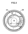
- Fig. 3 is a cross-sectional view taken along line 3-3 in Fig. 1;
- Fig. 4 is an enlarged cross-sectional side view of essential portions of the device shown in Fig. 1;
- Fig. 5 is a flow chart showing a technique for controlling an actuator
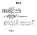
- Fig. 6 is a flowchart showing a technique for controlling the active anti-vibration supporting device when an abnormality is generated during an operational state of an engine
- Fig. 7 is a flowchart showing a technique for controlling the engine when an abnormality is generated during an operational state of the active anti-vibration supporting device.
- An active anti-vibration supporting device M shown in Figs. 1 to 4 resiliently supports a cylinder-suspendable type of an engine E on a vehicle body frame of an automobile.
- the active anti-vibration supporting device M is controlled by an electronic control unit U, which is connected to a crank pulse sensor S that detects a crank pulse output with the rotation of a crankshaft of the engine E.
- the crank pulse is output thirty six times per rotation of the crankshaft, namely, the crank pulse is output once for every crank angle of 10°.
- the active anti-vibration supporting device M has a structure substantially symmetric relative to an axis L, and includes an inner tube 12 welded to a plate-shaped mounting bracket 11 coupled to the engine E.
- An outer tube 13 is coaxially disposed around an outer periphery of the inner tube 12.
- An upper end and a lower end of a first elastic member 14, which is formed from a thick rubber, are bonded to the inner tube 12 and the outer tube 13 by vulcanization bonding, respectively.
- a disk-shaped first orifice-defining member 15 having an opening 15b at a central portion, a second orifice-defining member 16 formed into an annular shape having a tub-shaped or U-shaped section with an open upper surface, and a third orifice-defining member 17 formed into an annular shape also having a tub-shaped or U-shaped section with an open upper surface, are integrally connected together by welding.
- Outer peripheral portions of the first orifice-defining member 15 and the second orifice-defining member 16 are superposed on each other and fixed to a crimping portion 13a provided at a lower portion of the outer tube 13.
- a cap member 19 is fixed to an inner periphery of the second elastic member 18 by vulcanization bonding.
- the cap member 19 is also fixed to a vertically movable member 20 by press-fitting, the movable member 20 being disposed along the axis L.
- An outer periphery of a diaphragm 22 is fixed, by vulcanization bonding, to a ring member 21 that is fixed to the crimping portion 13a of the outer tube 13.
- a cap member 23 is fixed to an inner periphery of the diaphragm 22 by vulcanization bonding, and is fixed to the movable member 20 by press-fitting.
- a first liquid chamber 24, which sealedly contains liquid therein, is defined between the first elastic member 14 and the second elastic member 18.
- a second liquid chamber 25, which sealedly contains liquid therein, is defined between the second elastic member 18 and the diaphragm 22.
- the first liquid chamber 24 and the second liquid chamber 25 communicate with each other through an upper orifice 26 and a lower orifice 27 defined by the first, second, and third orifice-defining members 15, 16 and 17.
- the upper orifice 26 is an annular passage defined between the first orifice-defining member 15 and the second orifice-defining member 16.
- a communication bore 15a is formed in the first orifice-defining member 15 on one side of a partition wall 26a provided at a portion of the upper orifice 26.
- a communication bore 16a is formed in the second orifice-defining member 16 on the other side of the partition wall 26a. Therefore, the upper orifice 26 is substantially defined by a circle extending from the communication bore 15a in the first orifice-defining member 15 to the communication bore 16a in the second orifice-defining member 16 (see Fig. 2).
- the lower orifice 27 is an annular passage defined between the second orifice-defining member 16 and the third orifice-defining member 17.
- the communication bore 16a is formed in the second orifice-defining member 16 on one side of a partition wall 27a provided in a portion of the lower orifice 27.
- a communication bore 17a is formed in the third orifice-defining member 17 on the other side of the partition wall 27a. Therefore, the lower orifice 27 is substantially defined by another circle extending from the communication bore 16a in the second orifice-defining member 16 to the communication bore 17a in the third orifice-defining member 17 (see Fig. 3).
- the first liquid chamber 24 and the second liquid chamber 25 communicate with each other through the upper orifice 26 and the lower orifice 27, which are connected in series to each other.
- An actuator housing 30 is welded to a lower surface of the mounting bracket 28 and defines an outer shell of an actuator 29.
- a yoke 32 is fixed to a lower portion of the actuator housing 30, and a coil 34, which is wound around a bobbin 33, is accommodated in a space defined by the actuator housing 30 and the yoke 32.
- a bottomed cylindrical bearing 36 is fit within a cylindrical portion 32a of the yoke 32 and within an inner periphery of the annular coil 34.
- a disk-shaped armature 38 is slidably supported on an inner peripheral surface of the actuator housing 30 and opposite an upper surface of the coil 34.
- a step 38a formed on an inner periphery of the armature 38 is engaged with an upper portion of the bearing 36.
- the armature 38 is biased upwards by a spring 42, such as a Belleville-type spring, disposed between the armature 38 and an upper surface of the bobbin 33, and positioned to engage a locking portion 30a provided on the actuator housing 30.
- a cylindrical slider 43 is slidably fitted to an inner periphery of the bearing 36, and a shaft portion 20a, which extends downward from the movable member 20, is connected to a boss 44, which is passed loosely through an upper bottom of the bearing and fixed within the slider 43.
- a coil spring 41 is disposed between the bearing 36 and the slider 43, wherein the bearing 36 is biased upward and the slider 43 is biased downward by the coil spring 41.
- the movable member 20, connected to the slider 43 through the boss 44 and the shaft portion 20a, is lowered, and the second elastic member 18, connected to the movable member 20, is deformed downward to increase the volume of the first liquid chamber 24.
- the movable member 20 is raised, and the second elastic member 18 is deformed upward to decrease the volume of the first liquid chamber 24.
- the volume of the first liquid chamber 24 changes as an engine shake vibration of low frequency is generated during traveling of the automobile, and the liquid flows between the first liquid chamber 24 and the second liquid chamber 25, which are connected to each other via the upper orifice 26 and the lower orifice 27.
- the volume of the first liquid chamber 24 is increased or decreased, the volume of the second liquid chamber 25 correspondingly decreases or increases. Also, the change in volume of the second liquid chamber 25 is absorbed by the resilient deformation of the diaphragm 22.
- the vibration transmitted from the engine E to the vehicle body frame F is effectively damped because the shapes and sizes of the upper orifice 26 and the lower orifice 27, as well as the spring constant of the first elastic member 14, are set to exhibit a lower spring constant and a higher damping force in a range of the frequency of the engine shake vibration.
- the actuator 29 In the range of the frequency of the engine shake vibration, the actuator 29 is maintained in a non-operational state.
- the electronic control unit U controls the supply of electric current to the coil 34 based on a signal from the crank pulse sensor S. The contents of such control will be described in detail below with reference to a flowchart in Fig. 5.
- a crank pulse output from the crank pulse sensor S for every crank angle of 10° is read at Step S1.
- a time interval of the crank pulse is calculated at Step S2 by comparing the read crank pulse with a reference crank pulse, i.e., a particular cylinder TDC signal.
- a crank angular speed ⁇ is calculated by dividing the crank angle of 10° by the time interval of the crank pulse at Step S3.
- a crank angle acceleration d ⁇ /dt is calculated at Step S4 by differentiating the crank angular speed ⁇ by time.
- the torque Tq is 0 (zero).
- the angular speed ⁇ is increased due to an acceleration of a piston, and during a compression stroke, the angular speed ⁇ is decreased due to a deceleration of the piston, wherein a crank angle acceleration d ⁇ /dt is generated, and a torque Tq proportional to the crank angle acceleration d ⁇ /dt is generated.
- a maximum value and a minimum value of the torque adjacent each other in terms of time are determined at Step S6.
- An amplitude in the position of the active anti-vibration supporting device M supporting the engine E is calculated as a difference between the maximum and minimum values of the torque, namely, an amount of fluctuation in torque is calculated at Step S7.
- the amplitude corresponds to the magnitude of the vibration of the engine according to the present invention. If the amplitude is equal to or larger than a preset value at Step S8, a phase of the vibration of the engine is calculated at Step S9. The phase of the vibration of the engine is calculated from the crank angle provided when the torque attains a maximum value. On the other hand, if the amplitude is smaller than the preset value at Step S8, the phase of the vibration of the engine is fixed at a preset value at Step S10. A duty waveform and a timing, i.e., a phase, of electric current applied to the coil 34 of the actuator 29 are determined based on the calculated magnitude of the engine vibration and the calculated phase of the engine vibration (or a preset phase of the engine vibration) at Step S11.
- the volume of the first liquid chamber 24 is decreased to increase the liquid pressure, and the coil 34 is excited to attract the armature 38.
- the armature 38 is moved downward along with the slider 43 and the movable member 20, while compressing the coil springs 41 and 45, wherein the second elastic member 18, which is connected at an inner periphery to the movable member 20, is deformed downward.
- the volume of the first liquid chamber 24 increases to suppress an increase in liquid pressure and hence, the active anti-vibration supporting device M generates an active supporting force to prevent the downward transmission of a load from the engine E to the vehicle body frame F.
- the volume of the first liquid chamber 24 is increased to decrease the liquid pressure, and the coil 34 is de-excited to cancel the attraction of the armature 38.
- the armature 38 is moved upward along with the slider 43 and the movable member 20 by the resilient forces of the coil springs 41 and 45, wherein the second elastic member 18, which is connected at an inner periphery to the movable member 20, is deformed upward.
- the volume of the first liquid chamber 24 decreases to suppress a decrease in liquid pressure and hence, the active anti-vibration supporting device M generates an active supporting force to prevent the upward transmission of the load from the engine E to the vehicle body frame F.
- the active anti-vibration supporting device M exhibits an effective anti-vibration performance without being influenced by a variation in vibration characteristics of various engines or by a change in vibration characteristics due to the long-term use of the engine E.
- the actuator 29 is controlled based on the presumed magnitude of the engine vibration and the preset phase of the engine vibration. As such, even when it is difficult to presume the phase of the engine vibration, the actuator 29 is appropriately controlled, and the effective anti-vibration performance is exhibited by the active anti-vibration supporting device M.
- the active anti-vibration supporting device M is prevented from being operated uselessly in a state incapable of suppressing a large vibration of the engine E with an abnormality generated therein, and it is possible to previously avoid a situation in which the actuator 29 needlessly consumes electric power, and a situation in which the load of the active anti-vibration supporting device M is increased leading to a reduced durability.
- the abnormality in the operated state of the engine E includes, for example, an abnormality in a cylinder-stopping mechanism.
- the detection of such an abnormality is carried out by monitoring a cylinder-suspension switchover hydraulic pressure by a hydraulic pressure sensor, or by monitoring the wire breaking of a hydraulic pressure switchover solenoid valve.
- Step S32 If the operated state of the active anti-vibration supporting device M is normal at Step S32 in the flowchart of Fig. 7 during the control of the active anti-vibration supporting device M at Step S31, the control of the active anti-vibration supporting device M is continued at Step S33.
- Step S34 when an abnormality is generated in the operational state of the active anti-vibration supporting device M at Step S32, if the engine E is in a cylinder-suspended state at Step S34, the cylinder-suspended state is canceled at Step S35, wherein the engine E is restored to an all-cylinder operational state. If the engine E is not in the cylinder-suspended state at Step S34, the switchover to the cylinder-suspended state is prohibited.
- the abnormality in the operated state of the active anti-vibration supporting device M includes, for example, abnormalities in the actuator 29 and the electronic control unit U.
- the detection of such abnormality is carried out by monitoring the magnitude of electric current flowing through the actuator 29, or by monitoring the wire breaking based on a voltage in each of signal wires for the electronic control unit U.
- an anti-vibration support system for an engine comprising an active anti-vibration supporting device including an elastic member adapted to receive a vibration of the engine; a liquid chamber, wherein at least a portion of a wall surface of said liquid chamber is defined by said elastic member; a movable member adapted to change a volume of said liquid chamber; and an actuator that uses an electromagnetic force to drive said movable member, wherein the vibration of the engine is prevented from being transmitted to a vehicle body frame by controlling a supply of electric current to said actuator, and wherein operation of said active anti-vibration supporting device is prohibited when an abnormality in an operational state of the engine is detected.
Landscapes
- Engineering & Computer Science (AREA)
- General Engineering & Computer Science (AREA)
- Mechanical Engineering (AREA)
- Arrangement Or Mounting Of Propulsion Units For Vehicles (AREA)
- Combined Devices Of Dampers And Springs (AREA)
- Vibration Prevention Devices (AREA)
Abstract
Description
An anti-vibration support system for an engine, comprising an active anti-vibration supporting device including an elastic member adapted to receive a vibration of the engine; a liquid chamber, wherein at least a portion of a wall surface of said liquid chamber is defined by said elastic member; a movable member adapted to change a volume of said liquid chamber; and an actuator that uses an electromagnetic force to drive said movable member, wherein the vibration of the engine is prevented from being transmitted to a vehicle body frame by controlling a supply of electric current to said actuator, and wherein operation of said active anti-vibration supporting device is prohibited when an abnormality in an operational state of the engine is detected.
Claims (20)
- An anti-vibration support system for an engine, comprising an active anti-vibration supporting device including
an elastic member adapted to receive a vibration of the engine;
a liquid chamber, wherein at least a portion of a wall surface of said liquid chamber is defined by said elastic member;
a movable member adapted to change a volume of said liquid chamber; and
an actuator that uses an electromagnetic force to drive said movable member,
wherein the vibration of the engine is prevented from being transmitted to a vehicle body frame by controlling a supply of electric current to said actuator, and
wherein operation of said active anti-vibration supporting device is prohibited when an abnormality in an operational state of the engine is detected. - The anti-vibration system according to claim 1, wherein said elastic member is formed from rubber.
- The anti-vibration system according to claim 1, wherein said movable member is vertically movable and includes a shaft portion extending into said actuator.
- The anti-vibration system according to claim 1, wherein said actuator includes an outer shell defined by an actuator housing.
- The anti-vibration system according to claim 4, wherein a yoke is fixed to a lower portion of said actuator housing and a coil is accommodated within a space defined by said actuator housing and said yoke.
- The anti-vibration system according to claim 5, wherein a disk-shaped armature is slidably supported on an inner peripheral surface of said actuator housing and opposite an upper surface of said coil.
- The anti-vibration system according to claim 6, wherein a biasing member is disposed between said armature and an upper portion of a bobbin around which said coil is wound and biases said armature upward.
- The anti-vibration system according to claim 7, wherein a cylindrical slider is slidably fitted within a cylindrical portion of said yoke and includes a boss to which said shaft portion of said movable member is connected.
- The anti-vibration system according to claim 8, wherein a cylindrical bearing is slidably fitted between said cylindrical portion of said yoke and said cylindrical slider.
- The anti-vibration system according to claim 9, wherein a coiled biasing member is disposed between said cylindrical bearing and said cylindrical slider, and about said shaft portion of said movable member, and wherein said coiled biasing member biases said cylindrical bearing and said cylindrical slider in respective opposite directions.
- An anti-vibration support system for a cylinder-suspendable engine, comprising an active anti-vibration supporting device including
an elastic member adapted to receive a vibration of the engine;
a liquid chamber, wherein at least a portion of a wall surface of said liquid chamber is defined by said elastic member;
a movable member adapted to change a volume of said liquid chamber; and
an actuator that uses an electromagnetic force to drive said movable member,
wherein the vibration of the engine is prevented from being transmitted to a vehicle body frame by controlling a supply of electric current to said actuator, and
wherein the cylinder suspension of the engine is prohibited when an abnormality in an operational state of said active anti-vibration supporting device is detected. - The anti-vibration system according to claim 11, wherein said elastic member is formed from rubber.
- The anti-vibration system according to claim 11, wherein said movable member is vertically movable and includes a shaft portion extending into said actuator.
- The anti-vibration system according to claim 11, wherein said actuator includes an outer shell defined by an actuator housing.
- The anti-vibration system according to claim 14, wherein a yoke is fixed to a lower portion of said actuator housing and a coil is accommodated within a space defined by said actuator housing and said yoke.
- The anti-vibration system according to claim 15, wherein a disk-shaped armature is slidably supported on an inner peripheral surface of said actuator housing and opposite an upper surface of said coil.
- The anti-vibration system according to claim 16, wherein a biasing member is disposed between said armature and an upper portion of a bobbin around which said coil is wound and biases said armature upward.
- The anti-vibration system according to claim 17, wherein a cylindrical slider is slidably fitted within a cylindrical portion of said yoke and includes a boss to which said shaft portion of said movable member is connected.
- The anti-vibration system according to claim 18, wherein a cylindrical bearing is slidably fitted between said cylindrical portion of said yoke and said cylindrical slider.
- The anti-vibration system according to claim 19, wherein a coiled biasing member is disposed between said cylindrical bearing and said cylindrical slider, and about said shaft portion of said movable member, and wherein said coiled biasing member biases said cylindrical bearing and said cylindrical slider in respective opposite directions.
Applications Claiming Priority (2)
| Application Number | Priority Date | Filing Date | Title |
|---|---|---|---|
| JP2003056682 | 2003-03-04 | ||
| JP2003056682A JP4284399B2 (en) | 2003-03-04 | 2003-03-04 | Anti-vibration support device for engine |
Publications (3)
| Publication Number | Publication Date |
|---|---|
| EP1455112A2 true EP1455112A2 (en) | 2004-09-08 |
| EP1455112A3 EP1455112A3 (en) | 2004-11-10 |
| EP1455112B1 EP1455112B1 (en) | 2006-09-20 |
Family
ID=32821170
Family Applications (1)
| Application Number | Title | Priority Date | Filing Date |
|---|---|---|---|
| EP04005112A Expired - Lifetime EP1455112B1 (en) | 2003-03-04 | 2004-03-04 | Anti-vibration support system for engine |
Country Status (4)
| Country | Link |
|---|---|
| US (1) | US7946561B2 (en) |
| EP (1) | EP1455112B1 (en) |
| JP (1) | JP4284399B2 (en) |
| DE (1) | DE602004002417T2 (en) |
Cited By (3)
| Publication number | Priority date | Publication date | Assignee | Title |
|---|---|---|---|---|
| EP1677171A1 (en) * | 2004-12-28 | 2006-07-05 | Tokai Rubber Industries, Ltd. | Active vibration insulator |
| EP2351660A3 (en) * | 2007-08-10 | 2011-08-24 | Honda Motor Co., Ltd. | Active vibration isolating support apparatus and method for controlling the same |
| DE102006028345B4 (en) | 2005-06-21 | 2019-02-28 | GM Global Technology Operations LLC (n. d. Ges. d. Staates Delaware) | DEVICE FOR CONTROLLING A DYNAMIC TORQUE OF A MOTOR |
Families Citing this family (14)
| Publication number | Priority date | Publication date | Assignee | Title |
|---|---|---|---|---|
| DE102004035315B4 (en) | 2004-07-21 | 2023-06-29 | Bayerische Motoren Werke Aktiengesellschaft | Method for controlling an active bearing of a multi-cylinder reciprocating internal combustion engine |
| JP4662163B2 (en) | 2006-04-14 | 2011-03-30 | アイシン精機株式会社 | Vibration damping device |
| DE102007025735A1 (en) * | 2007-06-01 | 2008-12-04 | Bayerische Motoren Werke Aktiengesellschaft | Assembly bearing i.e. active assembly bearing, controlling method for use in motor vehicle, involves considering longitudinal dynamics, transverse dynamics and vertical dynamics of motor vehicle to provide potential relative movements |
| JP4861999B2 (en) * | 2008-01-23 | 2012-01-25 | 東海ゴム工業株式会社 | Fluid filled vibration isolator |
| JP4700742B2 (en) * | 2009-03-26 | 2011-06-15 | 本田技研工業株式会社 | Active anti-vibration support device |
| US8235351B1 (en) * | 2009-08-27 | 2012-08-07 | Lockheed Martin Corporation | Shock load isolation mounting |
| JP5448928B2 (en) * | 2010-02-26 | 2014-03-19 | 東海ゴム工業株式会社 | Fluid filled vibration isolator |
| JP5784912B2 (en) * | 2011-01-06 | 2015-09-24 | 東洋ゴム工業株式会社 | Vibration isolator |
| FI123240B (en) * | 2011-04-19 | 2012-12-31 | Waertsilae Finland Oy | Arrangement and method for preserving the alignment of an internal combustion engine and method for aligning an internal combustion engine and maintaining its alignment |
| DE102012009162B3 (en) * | 2012-05-03 | 2013-09-05 | Audi Ag | Method for operating engine mount for motor vehicle, involves moving control element to predetermined position by control unit in dependence on operating mode of motor vehicle, where position lies outside predetermined range |
| KR101845422B1 (en) * | 2016-04-19 | 2018-04-05 | 현대자동차주식회사 | Structure of active mount |
| JP6939454B2 (en) * | 2017-11-15 | 2021-09-22 | トヨタ自動車株式会社 | Engine mounting structure |
| JP2020139547A (en) * | 2019-02-27 | 2020-09-03 | 本田技研工業株式会社 | Variable rigidity anti-vibration device |
| JP2020139546A (en) * | 2019-02-27 | 2020-09-03 | 本田技研工業株式会社 | Variable rigidity anti-vibration device |
Family Cites Families (17)
| Publication number | Priority date | Publication date | Assignee | Title |
|---|---|---|---|---|
| US5163400A (en) * | 1990-01-16 | 1992-11-17 | Sawafuji Electric Co. Ltd. | Engine unit |
| JP3089869B2 (en) | 1992-12-25 | 2000-09-18 | 三菱自動車工業株式会社 | Automotive engine |
| JPH0642579A (en) | 1992-07-20 | 1994-02-15 | Mazda Motor Corp | Vehicle vibration reduction device |
| JPH0742783A (en) | 1993-07-28 | 1995-02-10 | Nippondenso Co Ltd | Electronically controlled engine mount |
| JP3430699B2 (en) * | 1995-03-31 | 2003-07-28 | 日産自動車株式会社 | Control type anti-vibration support device |
| JP3481046B2 (en) * | 1996-06-13 | 2003-12-22 | 本田技研工業株式会社 | Fault diagnosis method and apparatus in control system for active mounting of vehicle |
| JP3244457B2 (en) | 1997-09-03 | 2002-01-07 | トヨタ自動車株式会社 | Idle control method for internal combustion engine |
| JP3692815B2 (en) * | 1999-02-05 | 2005-09-07 | 東海ゴム工業株式会社 | Fluid filled active vibration isolator |
| DE19908907A1 (en) * | 1999-03-02 | 2000-09-28 | Daimler Chrysler Ag | Method and device for automatically influencing the driving behavior of a motor vehicle with an internal combustion engine |
| US6422546B1 (en) * | 1999-06-18 | 2002-07-23 | Honda Giken Kogyo Kabushiki Kaisha | Active vibration isolating support device |
| JP2001001766A (en) | 1999-06-18 | 2001-01-09 | Honda Motor Co Ltd | Active anti-vibration support device |
| JP3803220B2 (en) * | 1999-12-16 | 2006-08-02 | 株式会社日立製作所 | Engine system control device with electromagnetically driven intake and exhaust valves |
| JP2001304329A (en) * | 2000-04-19 | 2001-10-31 | Tokai Rubber Ind Ltd | Fluid-filled active engine mount |
| JP3715868B2 (en) * | 2000-06-15 | 2005-11-16 | 三菱電機株式会社 | Knock control device for internal combustion engine |
| JP2002097973A (en) | 2000-09-22 | 2002-04-05 | Honda Motor Co Ltd | Control device for internal combustion engine |
| US6641120B2 (en) * | 2001-07-31 | 2003-11-04 | Honda Giken Kogyo Kabushiki Kaisha | Method for controlling drive of actuator of active vibration isolation support system |
| JP3811469B2 (en) * | 2003-06-13 | 2006-08-23 | 本田技研工業株式会社 | Actuator drive controller for active anti-vibration support device |
-
2003
- 2003-03-04 JP JP2003056682A patent/JP4284399B2/en not_active Expired - Fee Related
-
2004
- 2004-02-24 US US10/784,891 patent/US7946561B2/en not_active Expired - Fee Related
- 2004-03-04 DE DE602004002417T patent/DE602004002417T2/en not_active Expired - Lifetime
- 2004-03-04 EP EP04005112A patent/EP1455112B1/en not_active Expired - Lifetime
Cited By (5)
| Publication number | Priority date | Publication date | Assignee | Title |
|---|---|---|---|---|
| EP1677171A1 (en) * | 2004-12-28 | 2006-07-05 | Tokai Rubber Industries, Ltd. | Active vibration insulator |
| US7403367B2 (en) | 2004-12-28 | 2008-07-22 | Tokai Rubber Industries, Ltd | Active vibration insulator |
| DE102006028345B4 (en) | 2005-06-21 | 2019-02-28 | GM Global Technology Operations LLC (n. d. Ges. d. Staates Delaware) | DEVICE FOR CONTROLLING A DYNAMIC TORQUE OF A MOTOR |
| EP2351660A3 (en) * | 2007-08-10 | 2011-08-24 | Honda Motor Co., Ltd. | Active vibration isolating support apparatus and method for controlling the same |
| US8763996B2 (en) | 2007-08-10 | 2014-07-01 | Honda Motor Co., Ltd. | Active vibration isolating support apparatus and method for controlling the same |
Also Published As
| Publication number | Publication date |
|---|---|
| JP4284399B2 (en) | 2009-06-24 |
| US20040232307A1 (en) | 2004-11-25 |
| DE602004002417D1 (en) | 2006-11-02 |
| US7946561B2 (en) | 2011-05-24 |
| DE602004002417T2 (en) | 2007-01-04 |
| EP1455112B1 (en) | 2006-09-20 |
| JP2004262389A (en) | 2004-09-24 |
| EP1455112A3 (en) | 2004-11-10 |
Similar Documents
| Publication | Publication Date | Title |
|---|---|---|
| EP1455112B1 (en) | Anti-vibration support system for engine | |
| US6641120B2 (en) | Method for controlling drive of actuator of active vibration isolation support system | |
| JP4176662B2 (en) | Vibration control method for hybrid vehicle | |
| JP2002139095A (en) | Actuator drive control method for active vibration isolation support device | |
| JP3803603B2 (en) | Actuator drive control method for active vibration isolation support device | |
| JP4243290B2 (en) | Active anti-vibration support device | |
| JP4323673B2 (en) | Vibration isolator | |
| JP3819876B2 (en) | Actuator drive controller for active anti-vibration support device | |
| JP4078321B2 (en) | Active anti-vibration support device | |
| JP3914177B2 (en) | Actuator drive controller for active anti-vibration support device | |
| JP2005249013A (en) | Active anti-vibration support device | |
| JP4110015B2 (en) | Actuator drive controller for active anti-vibration support device | |
| JP4929092B2 (en) | Anti-vibration support device for engine | |
| JP4110048B2 (en) | Actuator drive controller for active anti-vibration support device | |
| JP4036448B2 (en) | Actuator drive controller for active anti-vibration support device | |
| JP2007057074A (en) | Active anti-vibration support device | |
| JP2007321906A (en) | Solenoid actuator and active anti-vibration support device | |
| JP4615879B2 (en) | Active anti-vibration support device | |
| JP2005256931A (en) | Active anti-vibration support device | |
| JP2004036435A (en) | Vibration prevention control method for cylinder deactivated engine | |
| JP2006207633A (en) | Active anti-vibration support device | |
| JP2005280687A (en) | Anti-vibration control device for engine and anti-vibration control device for vehicle | |
| JP2004301297A (en) | Active anti-vibration support device | |
| JP2004036531A (en) | Engine vibration prevention control method | |
| JP2005249012A (en) | Active vibration isolation support device and cylinder deactivation engine control device |
Legal Events
| Date | Code | Title | Description |
|---|---|---|---|
| PUAI | Public reference made under article 153(3) epc to a published international application that has entered the european phase |
Free format text: ORIGINAL CODE: 0009012 |
|
| AK | Designated contracting states |
Kind code of ref document: A2 Designated state(s): AT BE BG CH CY CZ DE DK EE ES FI FR GB GR HU IE IT LI LU MC NL PL PT RO SE SI SK TR |
|
| AX | Request for extension of the european patent |
Extension state: AL LT LV MK |
|
| PUAL | Search report despatched |
Free format text: ORIGINAL CODE: 0009013 |
|
| AK | Designated contracting states |
Kind code of ref document: A3 Designated state(s): AT BE BG CH CY CZ DE DK EE ES FI FR GB GR HU IE IT LI LU MC NL PL PT RO SE SI SK TR |
|
| AX | Request for extension of the european patent |
Extension state: AL LT LV MK |
|
| 17P | Request for examination filed |
Effective date: 20041110 |
|
| 17Q | First examination report despatched |
Effective date: 20050315 |
|
| AKX | Designation fees paid |
Designated state(s): DE GB |
|
| GRAP | Despatch of communication of intention to grant a patent |
Free format text: ORIGINAL CODE: EPIDOSNIGR1 |
|
| GRAS | Grant fee paid |
Free format text: ORIGINAL CODE: EPIDOSNIGR3 |
|
| GRAA | (expected) grant |
Free format text: ORIGINAL CODE: 0009210 |
|
| AK | Designated contracting states |
Kind code of ref document: B1 Designated state(s): DE GB |
|
| REG | Reference to a national code |
Ref country code: GB Ref legal event code: FG4D |
|
| REF | Corresponds to: |
Ref document number: 602004002417 Country of ref document: DE Date of ref document: 20061102 Kind code of ref document: P |
|
| PLBE | No opposition filed within time limit |
Free format text: ORIGINAL CODE: 0009261 |
|
| STAA | Information on the status of an ep patent application or granted ep patent |
Free format text: STATUS: NO OPPOSITION FILED WITHIN TIME LIMIT |
|
| 26N | No opposition filed |
Effective date: 20070621 |
|
| PGFP | Annual fee paid to national office [announced via postgrant information from national office to epo] |
Ref country code: GB Payment date: 20110302 Year of fee payment: 8 |
|
| GBPC | Gb: european patent ceased through non-payment of renewal fee |
Effective date: 20120304 |
|
| REG | Reference to a national code |
Ref country code: DE Ref legal event code: R084 Ref document number: 602004002417 Country of ref document: DE Effective date: 20121113 |
|
| PG25 | Lapsed in a contracting state [announced via postgrant information from national office to epo] |
Ref country code: GB Free format text: LAPSE BECAUSE OF NON-PAYMENT OF DUE FEES Effective date: 20120304 |
|
| PGFP | Annual fee paid to national office [announced via postgrant information from national office to epo] |
Ref country code: DE Payment date: 20160302 Year of fee payment: 13 |
|
| REG | Reference to a national code |
Ref country code: DE Ref legal event code: R119 Ref document number: 602004002417 Country of ref document: DE |
|
| PG25 | Lapsed in a contracting state [announced via postgrant information from national office to epo] |
Ref country code: DE Free format text: LAPSE BECAUSE OF NON-PAYMENT OF DUE FEES Effective date: 20171003 |