EP1455092B1 - Batteriebetriebene Pumpe mit einer Steuereinrichtung - Google Patents
Batteriebetriebene Pumpe mit einer Steuereinrichtung Download PDFInfo
- Publication number
- EP1455092B1 EP1455092B1 EP04004954A EP04004954A EP1455092B1 EP 1455092 B1 EP1455092 B1 EP 1455092B1 EP 04004954 A EP04004954 A EP 04004954A EP 04004954 A EP04004954 A EP 04004954A EP 1455092 B1 EP1455092 B1 EP 1455092B1
- Authority
- EP
- European Patent Office
- Prior art keywords
- battery
- control device
- pump according
- pump
- motor
- Prior art date
- Legal status (The legal status is an assumption and is not a legal conclusion. Google has not performed a legal analysis and makes no representation as to the accuracy of the status listed.)
- Expired - Lifetime
Links
Images


Classifications
-
- F—MECHANICAL ENGINEERING; LIGHTING; HEATING; WEAPONS; BLASTING
- F04—POSITIVE - DISPLACEMENT MACHINES FOR LIQUIDS; PUMPS FOR LIQUIDS OR ELASTIC FLUIDS
- F04B—POSITIVE-DISPLACEMENT MACHINES FOR LIQUIDS; PUMPS
- F04B17/00—Pumps characterised by combination with, or adaptation to, specific driving engines or motors
- F04B17/03—Pumps characterised by combination with, or adaptation to, specific driving engines or motors driven by electric motors
-
- F—MECHANICAL ENGINEERING; LIGHTING; HEATING; WEAPONS; BLASTING
- F04—POSITIVE - DISPLACEMENT MACHINES FOR LIQUIDS; PUMPS FOR LIQUIDS OR ELASTIC FLUIDS
- F04D—NON-POSITIVE-DISPLACEMENT PUMPS
- F04D13/00—Pumping installations or systems
- F04D13/02—Units comprising pumps and their driving means
- F04D13/06—Units comprising pumps and their driving means the pump being electrically driven
- F04D13/068—Battery powered
-
- F—MECHANICAL ENGINEERING; LIGHTING; HEATING; WEAPONS; BLASTING
- F04—POSITIVE - DISPLACEMENT MACHINES FOR LIQUIDS; PUMPS FOR LIQUIDS OR ELASTIC FLUIDS
- F04D—NON-POSITIVE-DISPLACEMENT PUMPS
- F04D13/00—Pumping installations or systems
- F04D13/16—Pumping installations or systems with storage reservoirs
Definitions
- the invention relates to a battery-powered pump according to the preamble of claim 1.
- Battery operated pumps are particularly useful in gardens without their own power supply in the context of garden irrigation or to promote collected rainwater from wells, ponds or reservoirs.
- Of particular advantage is their use as a submersible pump, since the low battery voltage compared to the high mains voltage for the user is not critical.
- the WO 00/67368 describes an electric motor for a liquid pump, which is controlled by a PWM generator. It is not explained in detail, where a power specification comes from an operator for the electric motor.
- the US 4,836,147 describes a pump that can work with two different power levels and is used in a motor vehicle. The adjustment of the power levels is also done by pulse width modulation. More details about a performance specification by an operator are not mentioned here.
- the US 6,206,298 describes a pump with an electric motor that can be powered by a battery. However, an adjustment of the power of the electric motor is not mentioned herein at all.
- the US 6,189,811 describes a portable water pump that can be operated either with a battery or with a vehicle electrical system of a motor vehicle. An adjustment of the power of the pump is not mentioned.
- the object of the invention is therefore to avoid disadvantages of the prior art and in particular to increase the operating time of a battery-operated pump with a charge of the battery and to avoid overloading the battery.
- the main idea of the invention is to loop in between an engine and a battery for driving the motor, an adjustable control device, with which a power output of the battery to the engine is variably adjustable.
- the power output of the battery is switchable by the control device in several stages, wherein in one stage, the pump motor is coupled via the control device without limiting the power output directly to the battery, and in at least one further stage, the controller output the power delivered by the battery for the Pump motor limited.
- the power output can be adjusted continuously.
- the control device reduces the motor input voltage with respect to the battery voltage as a function of the predetermined power output.
- battery according to the invention of course also includes rechargeable batteries such as accumulators or the like.
- At least two further different stages are provided, in which the control device reduces the power consumption of the pump motor compared to the direct coupling to the battery.
- a stage "off" may be provided, in which the controller completely disconnects the battery from the pump motor.
- the individual possible power adjustment stages for the pump motor are visibly indicated by numbers.
- numbers Alternatively or in addition to a pure numbering, however, it is also possible to provide symbols which identify a particular application.
- the markings of the individual stages can be applied to the operating element and / or on a housing of the control device in the environment of the control element.
- the individual stages are set individually by the user with the operating element, i. by selecting discretely adjustable positions on the operating element, wherein the discretely adjustable positions are realized for example by haptic sensible by the user on the control detent positions, which relate to the individual applications of the pump.
- the selection of the individual applications of the pump with the control element is continuous or quasi-continuous. That is, the control does not have locking positions, via which the user receives a haptic feedback on a certain set position on the control, and the power output of the battery is continuously or quasi continuously adjustable by the control device.
- a control circuit is provided to reduce a transmission loss in the control device, for example a DC-DC converter. With this can be adjusted according to an application of the pump a transmission measure.
- the type of setting the transmission measure may be different.
- the control circuit is designed as a pulse width modulator (PWM), the duty cycle (switching time to period time) is adjustable according to the application of the pump, for example, over a range of 30% for a lowest power consumption of the engine to 100% for a maximum power consumption the pump motor.
- the duty cycle of 100% corresponds to a direct coupling of the pump motor to the battery.
- a switching element in particular an electronic switching element, such as a field effect transistor. This is switched on and off by switching cycles.
- control element is used to set a specific duty cycle in the control circuit, wherein discretely adjustable positions on the operating element for the duty cycles 0% position "off", battery is completely disconnected from the pump motor, about 33%, approx 67% and 100% - Direct coupling of the battery to the pump motor - are present.
- the electrical power drawn from the battery can be better adapted to the mechanical power required in the various applications and thus a battery life can be extended.
- a standard connection is provided on the control device, with which the control circuit can be connected to a corresponding low-voltage connection to a motor vehicle.
- a charging process for a rechargeable accumulator can also be controlled via the control device. For example, it can be adapted to different DC voltages. Furthermore, it is possible to provide a connection for a power cable and form the switching element with another part of the control circuit as a charger with rectifier. So an accumulator could be charged to a mains connection.
- Fig. 1 shows a conventional pump 1, which is designed for example as a submersible pump, with a pump housing 1.1 and a length-adjustable vertical outlet pipe 1.2. Instead of the outlet pipe 1.2, other types of lines can be connected to a corresponding connection on the pump housing 1.1.
- an unillustrated pump motor is arranged, which is supplied via a supply line 1.3, which is connectable to a control device 2 according to the invention, supplied by the control device 2 with energy.
- the control device 2 is shown for better representation of the connections to an operating position in the reverse position.
- the control device 2 which may be generally waterproof, comprises in the illustrated embodiment an output port 2.1, which is designed as an electrical connection socket. It can be connected to the supply line 1.3 via the mating connection 1.4 in order to supply the pump motor with energy. Furthermore, an operating element 2.2 for setting a power output required for an application of the pump, an input terminal 2.3 for an external power supply of the control device 2, which is designed as a socket for connecting a charger, and in the illustrated position to the rear by about 90 ° hinged hook for hanging the control device to a container wall and a housing 2.5 provided.
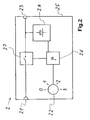
- a control circuit 2.6 designed as a pulse width modulator with a switching element 2.7, and a rechargeable battery 2.8 are arranged within the housing 2.5 of the control device 2, which are connected to one another via corresponding electrical connections as shown.
- the switching element 2.7 is preferably designed as an electronic switching element, for example as a field effect transistor.
- the operating element 2.2 is used to set a specific duty cycle in the control circuit 2.6, with which the control circuit 2.6 switches the switching element 2.7 on and off by means of corresponding clock signals.
- the maximum power output - 100% - is provided, for example, for a use case of the pump as a sprinkler, in which a high pressure and a large flow is needed.
- An average power output - 67% - is provided, for example, for a use case of the pump as a pouring shower or as a syringe in which a medium pressure and a medium flow rate is required.
- a low power output - 33% - is intended, for example, for a pump application to fill watering cans or for other water withdrawals that require low pressure at a pump outlet.
- the motor input voltage is reduced from typically 12 volts in the position '1' to 8 volts and in the position '2' to 10 volts.
- the stages are advantageously arranged in ascending order of performance.
- the user accessible on the control device housing 2.5 arranged control element 2.2 is designed as a rotary switch with fixed detent positions, via which the power output for the pump motor from the battery 2.8 is adjustable in several discrete stages.
- a control can be used with which the settings are made continuously without discrete steps and thus the power output is also continuously adjustable.
- mating connector 1.4 is preferably designed as a plug that does not fit into a mains voltage outlet.
- the plug can be designed so that it fits on a standard 12-volt connection and can be connected, for example, to a motor vehicle electrical system, so that the pump can be operated without the control device and without its own battery.
- the input terminal 2.3 for charging the battery 2.8 may be designed to be except a charger can be connected via a corresponding connection line with a motor vehicle electrical system.
- the output from the vehicle electrical system power with the control circuit 2.6 is also adjustable.
- any known 12 volt DC pump may be connected to the control device.
- Fig. 3 shows a diagram in which - based on the flow rate - pressure curves and efficiency curves ( ⁇ ) for different settings of the control device (motor input voltage is 8 volts, 10 volts, 12 volts) are entered on the flow rate. Values for the battery currents at selected measuring points are indicated along the pressure curve.
- a standard DC motor is generally used to advantage, in this example it may be a Mabuchi RS-555SH-4525.
Landscapes
- Engineering & Computer Science (AREA)
- Mechanical Engineering (AREA)
- General Engineering & Computer Science (AREA)
- Control Of Electric Motors In General (AREA)
- Control Of Non-Positive-Displacement Pumps (AREA)
- Control Of Positive-Displacement Pumps (AREA)
- Reciprocating Pumps (AREA)
Description
- Die Erfindung betrifft eine batteriebetriebene Pumpe nach dem Oberbegriff des Anspruchs 1.
- Batteriebetriebene Pumpen sind insbesondere in Gärten ohne eigenen Stromanschluss im Rahmen der Gartenbewässerung vorteilhaft einsetzbar oder um gesammeltes Regenwasser aus Brunnen, Teichen oder Sammelbehältern zu fördern. Von besonderem Vorteil ist ihr Einsatz als Tauchpumpe, da die niedrige Batteriespannung gegenüber der hohen Netzspannung für den Benutzer unkritisch ist.
- Batteriebetriebene Pumpen haben aber wie alle batteriebetriebenen Geräte das Problem, dass die Einsatzdauer durch die Batteriekapazität begrenzt ist.
- Die
WO 00/67368 - Die
US 4,836,147 beschreibt eine Pumpe, die mit zwei unterschiedlichen Leistungsstufen arbeiten kann und in einem Kraftfahrzeug verwendet wird. Die Einstellung der Leistungsstufen erfolgt ebenso durch Pulsweitenmodulation. Genauere Details zu einer Leistungsvorgabe durch einen Bediener sind hier nicht erwähnt. - Die
US 6,206,298 beschreibt eine Pumpe mit einem Elektromotor, der von einer Batterie gespeist sein kann. Eine Verstellung der Leistung des Elektromotors ist hierin jedoch überhaupt nicht erwähnt. - Die
US 6,189,811 beschreibt eine tragbare Wasserpumpe, die entweder mit einer Batterie oder mit einem Bordnetz eines Kraftfahrzeuges betrieben werden kann. Eine Verstellung der Leistung der Pumpe ist nicht erwähnt. - Die Aufgabe der Erfindung ist es daher, Nachteile des Standes der Technik zu vermeiden und insbesondere die Betriebszeit einer batteriebetriebenen Pumpe mit einer Ladung der Batterie zu erhöhen sowie eine Überlastung der Batterie zu vermeiden.
- Diese Aufgabe wird erfindungsgemäß mit den Merkmalen des Anspruchs 1 gelöst. Die abhängigen Ansprüche betreffen vorteilhafte Aus- und Weiterbildungen der Erfindung, welche im folgenden beschrieben werden. Der Wortlaut der Erfindung wird durch ausdrückliche Bezugnahme zum Inhalt der Beschreibung gemacht.
- Der Hauptgedanke der Erfindung besteht darin, zwischen einen Motor und eine Batterie zum Antrieb des Motors eine einstellbare Steuereinrichtung einzuschleifen, mit der eine Leistungsabgabe der Batterie an den Motor variabel einstellbar ist. Dadurch ist es in vorteilhafter Weise möglich, eine Leistungsaufnahme des Pumpenmotors gegenüber einem direkten Anschluss an die Batterie verlustarm auszuführen. Vorzugsweise ist die Leistungsabgabe der Batterie durch die Steuereinrichtung in mehreren Stufen schaltbar, wobei in einer Stufe der Pumpenmotor über die Steuereinrichtung ohne Begrenzung der Leistungsabgabe direkt an die Batterie angekoppelt ist, und in wenigstens einer weiteren Stufe die Steuereinrichtung die von der Batterie abgegebene Leistung für den Pumpenmotor begrenzt. Alternativ kann die Leistungsabgabe stufenlos eingestellt werden. Bevorzugt ist es möglich, dass die Steuereinrichtung die Motoreingangsspannung gegenüber der Batteriespannung in Abhängigkeit von der vorgegebenen Leistungsabgabe herabsetzt.
- Die Bezeichnung Batterie im Sinne der Erfindung umfasst selbstverständlich auch wiederaufladbare Batterien wie Akkumulatoren odgl.
- Vorzugsweise sind wenigstens zwei weitere unterschiedliche Stufen vorgesehen, bei denen die Steuereinrichtung die Leistungsaufnahme des Pumpenmotors gegenüber der direkten Ankopplung an die Batterie reduziert. Zusätzlich kann eine Stufe "Aus" vorgesehen sein, bei der die Steuereinrichtung die Batterie vollständig vom Pumpenmotor trennt.
- Vorzugsweise sind die einzelnen möglichen Stufen zur Leistungseinstellung für den Pumpenmotor sichtbar durch Ziffern bezeichnet. Alternativ oder zusätzlich zu einer reinen Durchnummerierung können aber auch Symbole vorgesehen sein, die einen jeweiligen Einsatzfall kennzeichnen. Die Markierungen der einzelnen Stufen können dabei auf dem Bedienelement und/oder auf einem Gehäuse der Steuereinrichtung im Umfeld des Bedienelementes aufgebracht sein.
- Bei einer möglichen Ausführungsform der Erfindung werden die einzelnen Stufen vom Benutzer mit dem Bedienelement einzeln eingestellt d.h. durch Auswahl von diskret am Bedienelement einstellbaren Positionen, wobei die diskret einstellbaren Positionen beispielsweise durch haptische vom Benutzer am Bedienelement erfühlbare Raststellungen realisiert sind, welche die einzelnen Einsatzfälle der Pumpe betreffen.
- Bei einer anderen Ausführungsform der Erfindung erfolgt die Auswahl der einzelnen Einsatzfälle der Pumpe mit dem Bedienelement kontinuierlich oder quasi kontinuierlich. D.h. das Bedienelement verfügt nicht über Rastpositionen, über welche der Benutzer eine haptische Rückmeldung über eine bestimmte eingestellte Position am Bedienelement erhält, und die Leistungsabgabe der Batterie ist von der Steuereinrichtung kontinuierlich oder quasi kontinuierlich einstellbar. Bei dieser Ausführungsform ist es besonders vorteilhaft, wenn am Bedienelement und/ oder am Gehäuse der Steuereinrichtung entsprechende Bezeichnungen der einzelnen Einsatzfälle der Pumpe vorhanden sind.
- Bei einer besonders vorteilhaften Ausführungsform der Erfindung ist zur Verringerung eines Übertragungsverlustes in der Steuereinrichtung eine Steuerschaltung vorgesehen, beispielsweise ein Gleichstromwandler. Mit dieser kann entsprechend einem Einsatzfall der Pumpe ein Übertragungsmaß eingestellt werden. Die Art der Einstellung des Übertragungsmaßes kann verschieden sein. In einer besonders einfachen Ausführungsform ist die Steuerschaltung als Pulsweitenmodulator (PWM) ausgeführt, dessen Tastverhältnis (Durchschaltezeit zu Periodenzeit) entsprechend des Einsatzfalles der Pumpe einstellbar ist, beispielsweise über einen Bereich von 30% für eine geringste Leistungsaufnahme des Motors bis 100 % für eine größte Leistungsaufnahme des Pumpenmotors. Dabei entspricht das Tastverhältnis von 100% einer direkten Ankopplung des Pumpenmotors an die Batterie.
- In der Steuereinrichtung kann zwischen einem Batterieanschluss und einem Anschluss für den Pumpenmotor ein Schaltelement eingeschleift sein, insbesondere ein elektronisches Schaltelement, beispielsweise ein Feldeffekttransistor. Dieses wird durch Schalttakte ein- und ausgeschaltet. Diese Maßnahmen haben den Vorteil, dass eine Verlustleistung am Schaltelement im wesentlichen nur an den Schaltflanken auftritt, welche sehr kurz gehalten werden können. Die Leistungsverluste im Schaltelement können bei gebräuchlichen Schaltungen auf wenige Prozent reduziert werden.
- Bei einer besonders einfachen Ausführungsform der Erfindung wird mit dem Bedienelement ein bestimmtes Tastverhältnis in der Steuerschaltung eingestellt, wobei diskret einstellbare Positionen am Bedienelement für die Tastverhältnisse 0% - Stellung "Aus", Batterie ist vollständig vom Pumpenmotor getrennt -, ca. 33%, ca. 67% und 100% - Direktankopplung der Batterie an den Pumpenmotor - vorhanden sind.
- Durch die beschriebene erfindungsgemäße Steuereinrichtung kann die der Batterie entnommene elektrische Leistung besser an die in den verschiedenen Einsatzfällen benötigte mechanische Leistung angepasst werden und damit eine Batteriestandzeit verlängert werden.
- Weiters ist es möglich, die Motoreingangsspannung an eine bestimmte Betriebsart anzupassen. Wenn keine besonders große Leistung benötigt wird, kann die Motoreingangsspannung abgesenkt werden, um die Batterie zu schonen.
- Bei einer weiteren vorteilhaften Ausführungsform der Erfindung ist an der Steuereinrichtung ein Standardanschluss vorgesehen, mit dem die Steuerschaltung mit einem entsprechenden Niederspannungsanschluss an einem Kraftfahrzeug verbunden werden kann. Dadurch kann die für den Betrieb der Pumpe benötigte Leistung aus einem Kraftfahrzeugbordnetz entnommen werden.
- Über die Steuereinrichtung kann auch ein Ladevorgang für einen wiederaufladbaren Akkumulator gesteuert werden. Es kann beispielsweise eine Anpassung an unterschiedlich große Gleichspannungen vorgenommen werden. Des weiteren ist es möglich, einen Anschluss für ein Netzkabel vorzusehen und das Schaltelement mit einem weiteren Teil der Steuerschaltung als Ladegerät mit Gleichrichter auszubilden. So könnte ein Akkumulator an einem Netzanschluss geladen werden.
- Diese und weitere Merkmale gehen außer aus den Ansprüchen auch aus der Beschreibung und den Zeichnungen hervor, wobei die einzelnen Merkmale jeweils für sich allein oder zu mehreren in Form von Unterkombinationen bei einer Ausführungsform der Erfindung und auf anderen Gebieten verwirklicht sein und vorteilhafte sowie für sich schutzfähige Ausführungen darstellen können, für die hier Schutz beansprucht wird. Die Unterteilung der Anmeldung in einzelne Abschnitte sowie Zwischen-Überschriften beschränken die unter diesen gemachten Aussagen nicht in ihrer Allgemeingültigkeit.
- Nachfolgend wird ein praktisches Ausführungsbeispiel anhand der schematisch Fig. 1 bis Fig. 3 näher beschrieben. Es zeigen:
- Fig. 1
- eine schematische Darstellung von Komponenten einer erfindungsgemäßen Pumpe;
- Fig. 2
- ein Blockschaltbild einer Steuerschaltung aus einer in Fig. 1 dargestellten Steuereinrichtung;
- Fig. 3
- ein Diagramm zur Darstellung von Druck- und Wirkungsgradkennlinien bezogen auf eine Durchflussmenge für unterschiedliche Einstellungen eines Übertragungsverhältnisses.
- Fig. 1 zeigt eine herkömmliche Pumpe 1, die beispielsweise als Tauchpumpe ausgeführt ist, mit einem Pumpengehäuse 1.1 und einem längenverstellbaren vertikalen Auslaufrohr 1.2. Anstelle des Auslaufrohres 1.2 können auch andere Leitungsarten an einen entsprechenden Anschluss am Pumpengehäuse 1.1 angeschlossen werden. Innerhalb des Pumpengehäuses 1.1 ist ein nicht dargestellter Pumpenmotor angeordnet, der über eine Versorungsleitung 1.3, die mit einer erfindungsgemäßen Steuereinrichtung 2 verbindbar ist, von der Steuereinrichtung 2 mit Energie versorgt wird. Die Steuereinrichtung 2 ist zur besseren Darstellung der Anschlüsse gegenüber einer Betriebslage in umgekehrter Position dargestellt.
- Die Steuereinrichtung 2, welche allgemein wasserdicht ausgeführt sein kann, umfasst im dargestellten Ausführungsbeispiel einen Ausgangsanschluss 2.1, der als elektrische Anschlussbuchse ausgeführt ist. Sie ist über den Gegenanschluss 1.4 mit der Versorgungsleitung 1.3 verbindbar, um den Pumpenmotor mit Energie zu versorgen. Des weiteren sind ein Bedienelement 2.2 zum Einstellen einer für einen Einsatzfall der Pumpe benötigten Leistungsabgabe, ein Eingangsanschluss 2.3 für eine externe Energieversorgung der Steuereinrichtung 2, der als Buchse zum Anschluss eines Ladegeräts ausgeführt ist, und ein in der dargestellten Stellung nach hinten um ca. 90° ausklappbaren Haken zum Einhängen der Steuereinrichtung an eine Behälterwand und ein Gehäuse 2.5 vorgesehen.
- Wie aus Fig. 2 ersichtlich ist, sind innerhalb des Gehäuses 2.5 der Steuereinrichtung 2 eine als Pulsweitenmodulator ausgeführte Steuerschaltung 2.6 mit einem Schaltelement 2.7, und eine wiederaufladbare Batterie 2.8 angeordnet, die wie dargestellt über entsprechende elektrische Verbindungen mit einander verschaltet sind. Das Schaltelement 2.7 ist vorzugsweise als elektronisches Schaltelement ausgeführt, beispielsweise als Feldeffekttransistor.
- In dem dargestellten einfachen Ausführungsbeispiel wird mit dem Bedienelement 2.2 ein bestimmtes Tastverhältnis in der Steuerschaltung 2.6 eingestellt, mit dem die Steuerschaltung 2.6 das Schaltelement 2.7 mittels entsprechender Taktsignale ein- und ausschaltet.
- Wie aus Fig. 2 weiter ersichtlich ist, sind zur Vereinfachung der Leistungsabgabeeinstellung Bezeichnungen vorgesehen, die eine Stellung ,0' - Tastverhältnis 0% bzw. Pumpe ist ausgeschaltet -, eine Stellung ,1' - Tastverhältnis ca. 33% -, eine Stellung ,2' - Tastverhältnis ca. 67% - und eine Stellung ,3' - Tastverhältnis 100% bzw. Direktverbindung der Batterie mit dem Pumpenmotor - bezeichnen.
- Die Maximalleistungsabgabe - 100% - ist beispielsweise für einen Einsatzfall der Pumpe als Regner vorgesehen, bei dem ein hoher Druck und ein großer Durchfluß benötigt wird. Eine mittlere Leistungsabgabe - 67% - ist beispielsweise für einen Einsatzfall der Pumpe als Gießbrause oder als Spritze vorgesehen, bei dem ein mittlerer Druck und ein mittlerer Durchfluß benötigt wird. Eine niedrige Leistungsabgabe - 33% - ist beispielsweise für einen Einsatzfall der Pumpe zum Befüllen von Gießkannen oder für andere Wasserentnahmen vorgesehen, bei welchen ein niedriger Druck an einem Pumpenausgang benötigt wird.
- Entsprechend des vom Benutzer mit dem Bedienelement 2.2 eingestellten Tastverhältnisses wird die Motoreingangsspannung von typischerweise 12 Volt in der Stellung ,1' auf 8 Volt und in der Stellung ,2' auf 10 Volt herabgesetzt. Dabei sind die Stufen vorteilhaft in aufsteigender Leistungsfolge angeordnet. Im dargestellten Ausführungsbeispiel ist das für den Benutzer zugängliche am Steuereinrichtungsgehäuse 2.5 angeordnete Bedienelement 2.2 als Drehschalter mit festen Raststellungen ausgeführt, über welches die Leistungsabgabe für den Pumpenmotor aus der Batterie 2.8 in mehreren diskreten Stufen einstellbar ist. Selbstverständlich kann auch ein Bedienelement verwendet werden, mit dem die Einstellungen kontinuierlich ohne diskrete Stufen vorgenommen werden und damit die Leistungsabgabe ebenfalls kontinuierlich einstellbar ist.
- Der am Ende der elektrischen Versorgungsleitung 1.3 angeordnete Gegenanschluss 1.4 ist vorzugsweise als Stecker ausgeführt, welcher nicht in eine Netzspannungssteckdose passt. Der Stecker kann aber so ausgelegt sein, dass er auf einen gängigen 12-Volt-Anschluß passt und so beispielsweise an ein Kraftfahrzeugbordnetz angeschlossen werden kann, so dass die Pumpe auch ohne die Steuereinrichtung und ohne eigenen Akku betreibbar ist. Desgleichen kann der Eingangsanschluss 2.3 zum Aufladen der Batterie 2.8 so ausgeführt sein, dass er außer mit einem Ladegerät über eine entsprechende Verbindungsleitung auch mit einem Kraftfahrzeugbordnetz verbunden werden kann. So ist die vom Kraftfahrzeugbordnetz abgegebene Leistung mit der Steuerschaltung 2.6 ebenfalls einstellbar.
- Anstelle der skizzierten Pumpe kann jede beliebige bekannte 12-Volt-Gleichstrompumpe an die Steuereinrichtung angeschlossen sein.
- Fig. 3 zeigt ein Diagramm, in welchem - bezogen auf die Durchflussmenge - Druckverläufe und Wirkungsgradverläufe (η) für unterschiedliche Einstellungen der Steuereinrichtung (Motoreingangsspannung ist 8 Volt, 10 Volt, 12 Volt) eingetragen sind über der Durchflußmenge. Entlang der Druckverlaufskurven sind noch Werte für die Batterieströme an ausgewählten Messpunkten angegeben. Als Elektromotor wird allgemein vorteilhaft ein Standard-Gleichstrommotor verwendet, in diesem Beispiel kann es ein Mabuchi RS-555SH-4525 sein.
Claims (13)
- Batteriebetriebene Pumpe (1) mit einem Motor und einer Batterie, wobei zwischen der Batterie (2.8) und dem Motor eine einstellbare Steuereinrichtung (2) zur Einstellung der Leistungsabgabe der Batterie (2.8) an den Motor eingeschleift ist, dadurch gekennzeichnet, dass die Leistungsabgabe der Batterie (2.8) an den Motor von einem Benutzer vorgebbar ist, wobei die Leistungsabgabe vom Benutzer in Abhängigkeit und/oder im Zusammenhang von einem Einsatzfall der Pumpe mit einem Bedienelement (2.2) vorgebbar ist.
- Pumpe nach Anspruch 1, dadurch gekennzeichnet, dass die Leistungsabgabe der Batterie (2.8) an den Motor in mehreren Stufen oder kontinuierlich einstellbar ist.
- Pumpe nach Anspruch 1 oder 2, dadurch gekennzeichnet, dass die Steuereinrichtung (2) die Motoreingangsspannung gegenüber der Batteriespannung in Abhängigkeit von der vorgegebenen Leistungsabgabe in Stufen oder kontinuierlich herabsetzt.
- Pumpe nach einem der vorherigen Ansprüche, dadurch gekennzeichnet, dass die Steuereinrichtung (2) eine Steuerschaltung (2.6) mit einem einstellbaren Übertragungsmaß umfasst, die vorzugsweise als Pulsweitenmodulator ausgeführt ist.
- Pumpe nach Anspruch 4, dadurch gekennzeichnet, dass das Übertragungsmaß durch Verändern eines Tastverhältnisses von Durchschaltzeit zu Zykluszeit einstellbar ist, wobei vorzugsweise das Tastverhältnis im Bereich von ca. 30% für die geringste mögliche Leistungsabgabe bis 100% für die größte mögliche Leistungsabgabe einstellbar ist.
- Pumpe nach einem der vorherigen Ansprüche, dadurch gekennzeichnet, dass die Steuereinrichtung (2) ein elektronisches Schaltelement (2.7) umfasst, welches in Abhängigkeit von Schalttakten ein- und ausschaltbar ist und das zwischen den Motor und die Batterie (2.8) eingeschleift ist.
- Pumpe nach einem der vorherigen Ansprüche, dadurch gekennzeichnet, dass die Steuereinrichtung (2) einen elektrischen Anschluss (2.3) aufweist, über den die Steuereinrichtung (2) mit einem Kraftfahrzeugbordnetz verbindbar ist.
- Pumpe nach Anspruch 1, dadurch gekennzeichnet, dass am Bedienelement (2.2) und/oder an einem Steuereinrichtungsgehäuse (2.5) die einem jeweiligen Einsatzfall entsprechende Leistungsabgabe durch Ziffern und/oder durch Symbole (2.8) bezeichnet ist, die den jeweiligen Einsatzfall angeben.
- Pumpe nach einem der Ansprüche 1 oder 8, dadurch gekennzeichnet, dass in einer ersten auswählbaren Stellung ('Aus') des Bedienelements (2.2) die Batterie (2.8) vollständig vom Motor getrennt ist.
- Pumpe nach einem der Ansprüche 1 oder 8 oder 9, dadurch gekennzeichnet, dass in einer zweiten Stellung des Bedienelements (2.2) eine erste Einsatzart mit einem hohen Druck und großem Durchfluß auswählbar ist.
- Pumpe nach einem der Ansprüche 1 oder 8 bis 10, dadurch gekennzeichnet, dass in einer dritten Stellung des Bedienelements (2.2) eine zweite Einsatzart mit einem mittleren Druck und einem mittleren Durchfluß auswählbar ist
- Pumpe nach einem der Ansprüche 1 oder 8 bis 11, dadurch gekennzeichnet, dass in einer vierten Stellung des Bedienelements (2.2) eine dritte Einsatzart mit einem geringen Druck und geringem Durchfluß auswählbar ist.
- Pumpe nach einem der vorhergehenden Ansprüche, dadurch gekennzeichnet, dass die Batterie (2.8) und/oder die Steuereinrichtung (2) separat von dem Pumpengehäuse (1.1) vorgesehen sind, wobei vorzugsweise zur Verbindung zwischen Pumpengehäuse (1.1) und Steuereinrichtung (2) eine Versorgungsleitung (1.3) vorgesehen ist.
Applications Claiming Priority (2)
| Application Number | Priority Date | Filing Date | Title |
|---|---|---|---|
| DE10309995A DE10309995A1 (de) | 2003-03-03 | 2003-03-03 | Batteriebetriebene Pumpe mit einer Steuereinrichtung |
| DE10309995 | 2003-03-03 |
Publications (3)
| Publication Number | Publication Date |
|---|---|
| EP1455092A2 EP1455092A2 (de) | 2004-09-08 |
| EP1455092A3 EP1455092A3 (de) | 2005-08-03 |
| EP1455092B1 true EP1455092B1 (de) | 2007-12-05 |
Family
ID=32797868
Family Applications (1)
| Application Number | Title | Priority Date | Filing Date |
|---|---|---|---|
| EP04004954A Expired - Lifetime EP1455092B1 (de) | 2003-03-03 | 2004-03-03 | Batteriebetriebene Pumpe mit einer Steuereinrichtung |
Country Status (3)
| Country | Link |
|---|---|
| EP (1) | EP1455092B1 (de) |
| AT (1) | ATE380296T1 (de) |
| DE (2) | DE10309995A1 (de) |
Cited By (1)
| Publication number | Priority date | Publication date | Assignee | Title |
|---|---|---|---|---|
| EP3827664A1 (de) * | 2019-11-29 | 2021-06-02 | Robert Bosch GmbH | Bewässerungssystem |
Families Citing this family (5)
| Publication number | Priority date | Publication date | Assignee | Title |
|---|---|---|---|---|
| HUE066209T2 (hu) | 2018-02-01 | 2024-07-28 | Husqvarna Ab | Szállításhoz levehetõen rögzített akkumulátortartó búvárszivattyúhoz |
| WO2019149840A1 (en) | 2018-02-01 | 2019-08-08 | Husqvarna Ab | Rain protection for battery of a submersible pump |
| WO2019149390A1 (en) | 2018-02-01 | 2019-08-08 | Husqvarna Ab | Rain protection for battery of a submersible pump |
| CN112177915B (zh) * | 2020-09-30 | 2022-07-22 | 浙江大元泵业股份有限公司 | 一种水泵的叶轮式水流检测方式、水流开关及水泵 |
| CN115788919A (zh) | 2021-09-09 | 2023-03-14 | 创科无线普通合伙 | 潜水泵 |
Family Cites Families (8)
| Publication number | Priority date | Publication date | Assignee | Title |
|---|---|---|---|---|
| US4256437A (en) * | 1978-02-01 | 1981-03-17 | Stewart Naumann Laboratories, Inc. | Peristaltic infusion pump and method |
| US4776766A (en) * | 1987-08-14 | 1988-10-11 | Interdynamics, Inc. | Portable air pump assembly and detechable safety lamp for automotive vehicle |
| US4836147A (en) * | 1987-12-14 | 1989-06-06 | Ford Motor Company | Cooling system for an internal combustion engine |
| US5580221A (en) * | 1994-10-05 | 1996-12-03 | Franklin Electric Co., Inc. | Motor drive circuit for pressure control of a pumping system |
| US6092992A (en) * | 1996-10-24 | 2000-07-25 | Imblum; Gregory G. | System and method for pump control and fault detection |
| US6206298B1 (en) * | 1998-01-05 | 2001-03-27 | T.L. Products Promoting Co., Ltd. | DC powered low resistance water pump and a waterworks display employing said pump |
| DE19919462A1 (de) * | 1999-04-29 | 2000-11-02 | Bosch Gmbh Robert | Elektronisch kommutierbarer Motor, insbesondere für eine Flüssigkeitspumpe |
| US6189811B1 (en) * | 1999-11-15 | 2001-02-20 | David Owen Rudy | Portable water-pumping system |
-
2003
- 2003-03-03 DE DE10309995A patent/DE10309995A1/de not_active Withdrawn
-
2004
- 2004-03-03 DE DE502004005635T patent/DE502004005635D1/de not_active Expired - Lifetime
- 2004-03-03 EP EP04004954A patent/EP1455092B1/de not_active Expired - Lifetime
- 2004-03-03 AT AT04004954T patent/ATE380296T1/de not_active IP Right Cessation
Cited By (1)
| Publication number | Priority date | Publication date | Assignee | Title |
|---|---|---|---|---|
| EP3827664A1 (de) * | 2019-11-29 | 2021-06-02 | Robert Bosch GmbH | Bewässerungssystem |
Also Published As
| Publication number | Publication date |
|---|---|
| EP1455092A3 (de) | 2005-08-03 |
| EP1455092A2 (de) | 2004-09-08 |
| ATE380296T1 (de) | 2007-12-15 |
| DE502004005635D1 (de) | 2008-01-17 |
| DE10309995A1 (de) | 2004-09-16 |
Similar Documents
| Publication | Publication Date | Title |
|---|---|---|
| DE102019208147B4 (de) | Schaltung zum laden von batterien und zur systemversorgung, die kapazitives und induktives laden kombiniert | |
| DE102019002209A1 (de) | Effiziente buck-boost-ladepumpe und verfahren dafür | |
| DE102010030937A1 (de) | Systeme und Verfahren für bidirektionale Energielieferung mit galvanischer Isolation | |
| EP0095072A1 (de) | Elektronisches Schaltnetzteil | |
| EP1026769A2 (de) | Vorrichtung zum Reaktivieren einer elektrischen Batterie | |
| DE202012102971U1 (de) | Schutzhülle mit der Funktion zur umgekehrten Entladung eines Handheld-Gerätes | |
| DE102013208720A1 (de) | Leistungswandlerschaltkreis und Verfahren zum Betrieb eines Leistungswandlerschaltkreises | |
| EP0619432B1 (de) | Anlage mit mindestens einer Flüssigkeitspumpe | |
| EP1455092A2 (de) | Batteriebetriebene Pumpe mit einer Steuereinrichtung | |
| WO2006063823A2 (de) | Laderegleranordnung und verfahren zum aufladen einer batterie | |
| EP3332466A1 (de) | Polwender und blindleistungsfähiger wechselrichter sowie polwendeverfahren | |
| WO1998040949A1 (de) | Schaltungsanordnung zum versorgen eines verbrauchers mit elektrischer energie | |
| EP4176506B1 (de) | Kompakte leistungsladeeinrichtung | |
| DE2014377A1 (de) | Transistor-Wandlerschaltung | |
| EP1376724A1 (de) | Hybridenergiequelle | |
| EP0063756A1 (de) | Elektrospeicher-Strassenfahrzeug | |
| CN103916006B (zh) | 一种感性器件的驱动电路 | |
| EP2290240A2 (de) | Pumpe mit Netzgeräteregler | |
| DE10061738A1 (de) | DC/DC-Wandler | |
| DE102017211186A1 (de) | Schaltkreis mit variabler Ausgabe und einer Wandlersteuerung mit demselben Schaltkreis | |
| DE102009005265A1 (de) | Lastansteuerungsschaltung in einem Kraftfahrzeugsteuergerät | |
| DE3440978A1 (de) | Anordnung zum betrieb von fluessigkeitspumpen mittels solarzellen | |
| EP1992060B1 (de) | Vorrichtung und verfahren zur gleichspannungsversorgung von elektronischen ansteuerschaltungen für elektromotoren | |
| US20030042858A1 (en) | Motor driver circuit to operate in limited power environment | |
| DE4104033A1 (de) | Solarbetriebene pumpanlage zur wasserversorgung insbesondere von kleingaerten, auffuellen von regentonnen und aufrechterhaltung des wasserstandes von gartenteichen |
Legal Events
| Date | Code | Title | Description |
|---|---|---|---|
| PUAI | Public reference made under article 153(3) epc to a published international application that has entered the european phase |
Free format text: ORIGINAL CODE: 0009012 |
|
| AK | Designated contracting states |
Kind code of ref document: A2 Designated state(s): AT BE BG CH CY CZ DE DK EE ES FI FR GB GR HU IE IT LI LU MC NL PL PT RO SE SI SK TR |
|
| AX | Request for extension of the european patent |
Extension state: AL LT LV MK |
|
| PUAL | Search report despatched |
Free format text: ORIGINAL CODE: 0009013 |
|
| AK | Designated contracting states |
Kind code of ref document: A3 Designated state(s): AT BE BG CH CY CZ DE DK EE ES FI FR GB GR HU IE IT LI LU MC NL PL PT RO SE SI SK TR |
|
| AX | Request for extension of the european patent |
Extension state: AL LT LV MK |
|
| 17P | Request for examination filed |
Effective date: 20051214 |
|
| AKX | Designation fees paid |
Designated state(s): AT BE BG CH CY CZ DE DK EE ES FI FR GB GR HU IE IT LI LU MC NL PL PT RO SE SI SK TR |
|
| GRAP | Despatch of communication of intention to grant a patent |
Free format text: ORIGINAL CODE: EPIDOSNIGR1 |
|
| GRAS | Grant fee paid |
Free format text: ORIGINAL CODE: EPIDOSNIGR3 |
|
| GRAA | (expected) grant |
Free format text: ORIGINAL CODE: 0009210 |
|
| AK | Designated contracting states |
Kind code of ref document: B1 Designated state(s): AT BE BG CH CY CZ DE DK EE ES FI FR GB GR HU IE IT LI LU MC NL PL PT RO SE SI SK TR |
|
| REG | Reference to a national code |
Ref country code: GB Ref legal event code: FG4D Free format text: NOT ENGLISH |
|
| REG | Reference to a national code |
Ref country code: IE Ref legal event code: FG4D Free format text: LANGUAGE OF EP DOCUMENT: GERMAN |
|
| REG | Reference to a national code |
Ref country code: CH Ref legal event code: EP |
|
| REF | Corresponds to: |
Ref document number: 502004005635 Country of ref document: DE Date of ref document: 20080117 Kind code of ref document: P |
|
| PG25 | Lapsed in a contracting state [announced via postgrant information from national office to epo] |
Ref country code: SE Free format text: LAPSE BECAUSE OF FAILURE TO SUBMIT A TRANSLATION OF THE DESCRIPTION OR TO PAY THE FEE WITHIN THE PRESCRIBED TIME-LIMIT Effective date: 20080305 Ref country code: ES Free format text: LAPSE BECAUSE OF FAILURE TO SUBMIT A TRANSLATION OF THE DESCRIPTION OR TO PAY THE FEE WITHIN THE PRESCRIBED TIME-LIMIT Effective date: 20080316 |
|
| PG25 | Lapsed in a contracting state [announced via postgrant information from national office to epo] |
Ref country code: PL Free format text: LAPSE BECAUSE OF FAILURE TO SUBMIT A TRANSLATION OF THE DESCRIPTION OR TO PAY THE FEE WITHIN THE PRESCRIBED TIME-LIMIT Effective date: 20071205 Ref country code: FI Free format text: LAPSE BECAUSE OF FAILURE TO SUBMIT A TRANSLATION OF THE DESCRIPTION OR TO PAY THE FEE WITHIN THE PRESCRIBED TIME-LIMIT Effective date: 20071205 Ref country code: SI Free format text: LAPSE BECAUSE OF FAILURE TO SUBMIT A TRANSLATION OF THE DESCRIPTION OR TO PAY THE FEE WITHIN THE PRESCRIBED TIME-LIMIT Effective date: 20071205 |
|
| GBV | Gb: ep patent (uk) treated as always having been void in accordance with gb section 77(7)/1977 [no translation filed] | ||
| PG25 | Lapsed in a contracting state [announced via postgrant information from national office to epo] |
Ref country code: CZ Free format text: LAPSE BECAUSE OF FAILURE TO SUBMIT A TRANSLATION OF THE DESCRIPTION OR TO PAY THE FEE WITHIN THE PRESCRIBED TIME-LIMIT Effective date: 20071205 |
|
| ET | Fr: translation filed | ||
| PG25 | Lapsed in a contracting state [announced via postgrant information from national office to epo] |
Ref country code: SK Free format text: LAPSE BECAUSE OF FAILURE TO SUBMIT A TRANSLATION OF THE DESCRIPTION OR TO PAY THE FEE WITHIN THE PRESCRIBED TIME-LIMIT Effective date: 20071205 Ref country code: RO Free format text: LAPSE BECAUSE OF FAILURE TO SUBMIT A TRANSLATION OF THE DESCRIPTION OR TO PAY THE FEE WITHIN THE PRESCRIBED TIME-LIMIT Effective date: 20071205 |
|
| PG25 | Lapsed in a contracting state [announced via postgrant information from national office to epo] |
Ref country code: PT Free format text: LAPSE BECAUSE OF FAILURE TO SUBMIT A TRANSLATION OF THE DESCRIPTION OR TO PAY THE FEE WITHIN THE PRESCRIBED TIME-LIMIT Effective date: 20080505 |
|
| REG | Reference to a national code |
Ref country code: IE Ref legal event code: FD4D |
|
| PLBE | No opposition filed within time limit |
Free format text: ORIGINAL CODE: 0009261 |
|
| STAA | Information on the status of an ep patent application or granted ep patent |
Free format text: STATUS: NO OPPOSITION FILED WITHIN TIME LIMIT |
|
| PG25 | Lapsed in a contracting state [announced via postgrant information from national office to epo] |
Ref country code: IE Free format text: LAPSE BECAUSE OF FAILURE TO SUBMIT A TRANSLATION OF THE DESCRIPTION OR TO PAY THE FEE WITHIN THE PRESCRIBED TIME-LIMIT Effective date: 20071205 Ref country code: DK Free format text: LAPSE BECAUSE OF FAILURE TO SUBMIT A TRANSLATION OF THE DESCRIPTION OR TO PAY THE FEE WITHIN THE PRESCRIBED TIME-LIMIT Effective date: 20071205 Ref country code: MC Free format text: LAPSE BECAUSE OF NON-PAYMENT OF DUE FEES Effective date: 20080331 |
|
| REG | Reference to a national code |
Ref country code: CH Ref legal event code: PL |
|
| 26N | No opposition filed |
Effective date: 20080908 |
|
| PG25 | Lapsed in a contracting state [announced via postgrant information from national office to epo] |
Ref country code: GB Free format text: LAPSE BECAUSE OF FAILURE TO SUBMIT A TRANSLATION OF THE DESCRIPTION OR TO PAY THE FEE WITHIN THE PRESCRIBED TIME-LIMIT Effective date: 20071205 |
|
| PG25 | Lapsed in a contracting state [announced via postgrant information from national office to epo] |
Ref country code: GR Free format text: LAPSE BECAUSE OF FAILURE TO SUBMIT A TRANSLATION OF THE DESCRIPTION OR TO PAY THE FEE WITHIN THE PRESCRIBED TIME-LIMIT Effective date: 20080306 Ref country code: LI Free format text: LAPSE BECAUSE OF NON-PAYMENT OF DUE FEES Effective date: 20080331 Ref country code: CH Free format text: LAPSE BECAUSE OF NON-PAYMENT OF DUE FEES Effective date: 20080331 Ref country code: EE Free format text: LAPSE BECAUSE OF FAILURE TO SUBMIT A TRANSLATION OF THE DESCRIPTION OR TO PAY THE FEE WITHIN THE PRESCRIBED TIME-LIMIT Effective date: 20071205 |
|
| PG25 | Lapsed in a contracting state [announced via postgrant information from national office to epo] |
Ref country code: BG Free format text: LAPSE BECAUSE OF FAILURE TO SUBMIT A TRANSLATION OF THE DESCRIPTION OR TO PAY THE FEE WITHIN THE PRESCRIBED TIME-LIMIT Effective date: 20080305 |
|
| PG25 | Lapsed in a contracting state [announced via postgrant information from national office to epo] |
Ref country code: CY Free format text: LAPSE BECAUSE OF FAILURE TO SUBMIT A TRANSLATION OF THE DESCRIPTION OR TO PAY THE FEE WITHIN THE PRESCRIBED TIME-LIMIT Effective date: 20071205 |
|
| PGFP | Annual fee paid to national office [announced via postgrant information from national office to epo] |
Ref country code: AT Payment date: 20100121 Year of fee payment: 7 Ref country code: BE Payment date: 20100121 Year of fee payment: 7 |
|
| PG25 | Lapsed in a contracting state [announced via postgrant information from national office to epo] |
Ref country code: LU Free format text: LAPSE BECAUSE OF NON-PAYMENT OF DUE FEES Effective date: 20080303 Ref country code: HU Free format text: LAPSE BECAUSE OF FAILURE TO SUBMIT A TRANSLATION OF THE DESCRIPTION OR TO PAY THE FEE WITHIN THE PRESCRIBED TIME-LIMIT Effective date: 20080606 |
|
| PG25 | Lapsed in a contracting state [announced via postgrant information from national office to epo] |
Ref country code: TR Free format text: LAPSE BECAUSE OF FAILURE TO SUBMIT A TRANSLATION OF THE DESCRIPTION OR TO PAY THE FEE WITHIN THE PRESCRIBED TIME-LIMIT Effective date: 20071205 |
|
| PG25 | Lapsed in a contracting state [announced via postgrant information from national office to epo] |
Ref country code: IT Free format text: LAPSE BECAUSE OF NON-PAYMENT OF DUE FEES Effective date: 20080331 |
|
| BERE | Be: lapsed |
Owner name: GARDENA MANUFACTURING G.M.B.H. Effective date: 20110331 |
|
| REG | Reference to a national code |
Ref country code: NL Ref legal event code: V1 Effective date: 20111001 |
|
| PG25 | Lapsed in a contracting state [announced via postgrant information from national office to epo] |
Ref country code: AT Free format text: LAPSE BECAUSE OF NON-PAYMENT OF DUE FEES Effective date: 20110303 |
|
| PG25 | Lapsed in a contracting state [announced via postgrant information from national office to epo] |
Ref country code: BE Free format text: LAPSE BECAUSE OF NON-PAYMENT OF DUE FEES Effective date: 20110331 |
|
| PG25 | Lapsed in a contracting state [announced via postgrant information from national office to epo] |
Ref country code: NL Free format text: LAPSE BECAUSE OF NON-PAYMENT OF DUE FEES Effective date: 20111001 |
|
| REG | Reference to a national code |
Ref country code: FR Ref legal event code: TP Owner name: HUSQVARNA AB, SE Effective date: 20140407 |
|
| REG | Reference to a national code |
Ref country code: DE Ref legal event code: R081 Ref document number: 502004005635 Country of ref document: DE Owner name: HUSQVARNA AB, SE Free format text: FORMER OWNER: GARDENA MANUFACTURING GMBH, 89079 ULM, DE Effective date: 20140627 |
|
| PGFP | Annual fee paid to national office [announced via postgrant information from national office to epo] |
Ref country code: NL Payment date: 20100331 Year of fee payment: 7 |
|
| REG | Reference to a national code |
Ref country code: FR Ref legal event code: PLFP Year of fee payment: 13 |
|
| REG | Reference to a national code |
Ref country code: FR Ref legal event code: PLFP Year of fee payment: 14 |
|
| REG | Reference to a national code |
Ref country code: FR Ref legal event code: PLFP Year of fee payment: 15 |
|
| PGFP | Annual fee paid to national office [announced via postgrant information from national office to epo] |
Ref country code: FR Payment date: 20230217 Year of fee payment: 20 |
|
| PGFP | Annual fee paid to national office [announced via postgrant information from national office to epo] |
Ref country code: DE Payment date: 20230206 Year of fee payment: 20 |
|
| P01 | Opt-out of the competence of the unified patent court (upc) registered |
Effective date: 20230419 |
|
| REG | Reference to a national code |
Ref country code: DE Ref legal event code: R071 Ref document number: 502004005635 Country of ref document: DE |