EP1455080A2 - Method of making a melt-blown filter medium for use in filters in internal combustion engines and product - Google Patents
Method of making a melt-blown filter medium for use in filters in internal combustion engines and product Download PDFInfo
- Publication number
- EP1455080A2 EP1455080A2 EP04251190A EP04251190A EP1455080A2 EP 1455080 A2 EP1455080 A2 EP 1455080A2 EP 04251190 A EP04251190 A EP 04251190A EP 04251190 A EP04251190 A EP 04251190A EP 1455080 A2 EP1455080 A2 EP 1455080A2
- Authority
- EP
- European Patent Office
- Prior art keywords
- filter medium
- melt
- fibers
- profile
- collection means
- Prior art date
- Legal status (The legal status is an assumption and is not a legal conclusion. Google has not performed a legal analysis and makes no representation as to the accuracy of the status listed.)
- Withdrawn
Links
Images


Classifications
-
- F—MECHANICAL ENGINEERING; LIGHTING; HEATING; WEAPONS; BLASTING
- F02—COMBUSTION ENGINES; HOT-GAS OR COMBUSTION-PRODUCT ENGINE PLANTS
- F02M—SUPPLYING COMBUSTION ENGINES IN GENERAL WITH COMBUSTIBLE MIXTURES OR CONSTITUENTS THEREOF
- F02M35/00—Combustion-air cleaners, air intakes, intake silencers, or induction systems specially adapted for, or arranged on, internal-combustion engines
- F02M35/02—Air cleaners
- F02M35/024—Air cleaners using filters, e.g. moistened
-
- B—PERFORMING OPERATIONS; TRANSPORTING
- B01—PHYSICAL OR CHEMICAL PROCESSES OR APPARATUS IN GENERAL
- B01D—SEPARATION
- B01D29/00—Filters with filtering elements stationary during filtration, e.g. pressure or suction filters, not covered by groups B01D24/00 - B01D27/00; Filtering elements therefor
- B01D29/01—Filters with filtering elements stationary during filtration, e.g. pressure or suction filters, not covered by groups B01D24/00 - B01D27/00; Filtering elements therefor with flat filtering elements
- B01D29/012—Making filtering elements
-
- B—PERFORMING OPERATIONS; TRANSPORTING
- B01—PHYSICAL OR CHEMICAL PROCESSES OR APPARATUS IN GENERAL
- B01D—SEPARATION
- B01D29/00—Filters with filtering elements stationary during filtration, e.g. pressure or suction filters, not covered by groups B01D24/00 - B01D27/00; Filtering elements therefor
- B01D29/01—Filters with filtering elements stationary during filtration, e.g. pressure or suction filters, not covered by groups B01D24/00 - B01D27/00; Filtering elements therefor with flat filtering elements
- B01D29/016—Filters with filtering elements stationary during filtration, e.g. pressure or suction filters, not covered by groups B01D24/00 - B01D27/00; Filtering elements therefor with flat filtering elements with corrugated, folded or wound filtering elements
-
- B—PERFORMING OPERATIONS; TRANSPORTING
- B01—PHYSICAL OR CHEMICAL PROCESSES OR APPARATUS IN GENERAL
- B01D—SEPARATION
- B01D39/00—Filtering material for liquid or gaseous fluids
- B01D39/14—Other self-supporting filtering material ; Other filtering material
- B01D39/16—Other self-supporting filtering material ; Other filtering material of organic material, e.g. synthetic fibres
- B01D39/1607—Other self-supporting filtering material ; Other filtering material of organic material, e.g. synthetic fibres the material being fibrous
- B01D39/1623—Other self-supporting filtering material ; Other filtering material of organic material, e.g. synthetic fibres the material being fibrous of synthetic origin
-
- B—PERFORMING OPERATIONS; TRANSPORTING
- B01—PHYSICAL OR CHEMICAL PROCESSES OR APPARATUS IN GENERAL
- B01D—SEPARATION
- B01D46/00—Filters or filtering processes specially modified for separating dispersed particles from gases or vapours
- B01D46/0001—Making filtering elements
-
- B—PERFORMING OPERATIONS; TRANSPORTING
- B01—PHYSICAL OR CHEMICAL PROCESSES OR APPARATUS IN GENERAL
- B01D—SEPARATION
- B01D46/00—Filters or filtering processes specially modified for separating dispersed particles from gases or vapours
- B01D46/10—Particle separators, e.g. dust precipitators, using filter plates, sheets or pads having plane surfaces
-
- B—PERFORMING OPERATIONS; TRANSPORTING
- B01—PHYSICAL OR CHEMICAL PROCESSES OR APPARATUS IN GENERAL
- B01D—SEPARATION
- B01D46/00—Filters or filtering processes specially modified for separating dispersed particles from gases or vapours
- B01D46/52—Particle separators, e.g. dust precipitators, using filters embodying folded corrugated or wound sheet material
- B01D46/521—Particle separators, e.g. dust precipitators, using filters embodying folded corrugated or wound sheet material using folded, pleated material
-
- D—TEXTILES; PAPER
- D04—BRAIDING; LACE-MAKING; KNITTING; TRIMMINGS; NON-WOVEN FABRICS
- D04H—MAKING TEXTILE FABRICS, e.g. FROM FIBRES OR FILAMENTARY MATERIAL; FABRICS MADE BY SUCH PROCESSES OR APPARATUS, e.g. FELTS, NON-WOVEN FABRICS; COTTON-WOOL; WADDING ; NON-WOVEN FABRICS FROM STAPLE FIBRES, FILAMENTS OR YARNS, BONDED WITH AT LEAST ONE WEB-LIKE MATERIAL DURING THEIR CONSOLIDATION
- D04H1/00—Non-woven fabrics formed wholly or mainly of staple fibres or like relatively short fibres
- D04H1/40—Non-woven fabrics formed wholly or mainly of staple fibres or like relatively short fibres from fleeces or layers composed of fibres without existing or potential cohesive properties
- D04H1/54—Non-woven fabrics formed wholly or mainly of staple fibres or like relatively short fibres from fleeces or layers composed of fibres without existing or potential cohesive properties by welding together the fibres, e.g. by partially melting or dissolving
- D04H1/56—Non-woven fabrics formed wholly or mainly of staple fibres or like relatively short fibres from fleeces or layers composed of fibres without existing or potential cohesive properties by welding together the fibres, e.g. by partially melting or dissolving in association with fibre formation, e.g. immediately following extrusion of staple fibres
-
- D—TEXTILES; PAPER
- D04—BRAIDING; LACE-MAKING; KNITTING; TRIMMINGS; NON-WOVEN FABRICS
- D04H—MAKING TEXTILE FABRICS, e.g. FROM FIBRES OR FILAMENTARY MATERIAL; FABRICS MADE BY SUCH PROCESSES OR APPARATUS, e.g. FELTS, NON-WOVEN FABRICS; COTTON-WOOL; WADDING ; NON-WOVEN FABRICS FROM STAPLE FIBRES, FILAMENTS OR YARNS, BONDED WITH AT LEAST ONE WEB-LIKE MATERIAL DURING THEIR CONSOLIDATION
- D04H1/00—Non-woven fabrics formed wholly or mainly of staple fibres or like relatively short fibres
- D04H1/70—Non-woven fabrics formed wholly or mainly of staple fibres or like relatively short fibres characterised by the method of forming fleeces or layers, e.g. reorientation of fibres
- D04H1/72—Non-woven fabrics formed wholly or mainly of staple fibres or like relatively short fibres characterised by the method of forming fleeces or layers, e.g. reorientation of fibres the fibres being randomly arranged
-
- D—TEXTILES; PAPER
- D04—BRAIDING; LACE-MAKING; KNITTING; TRIMMINGS; NON-WOVEN FABRICS
- D04H—MAKING TEXTILE FABRICS, e.g. FROM FIBRES OR FILAMENTARY MATERIAL; FABRICS MADE BY SUCH PROCESSES OR APPARATUS, e.g. FELTS, NON-WOVEN FABRICS; COTTON-WOOL; WADDING ; NON-WOVEN FABRICS FROM STAPLE FIBRES, FILAMENTS OR YARNS, BONDED WITH AT LEAST ONE WEB-LIKE MATERIAL DURING THEIR CONSOLIDATION
- D04H3/00—Non-woven fabrics formed wholly or mainly of yarns or like filamentary material of substantial length
- D04H3/02—Non-woven fabrics formed wholly or mainly of yarns or like filamentary material of substantial length characterised by the method of forming fleeces or layers, e.g. reorientation of yarns or filaments
- D04H3/03—Non-woven fabrics formed wholly or mainly of yarns or like filamentary material of substantial length characterised by the method of forming fleeces or layers, e.g. reorientation of yarns or filaments at random
-
- D—TEXTILES; PAPER
- D04—BRAIDING; LACE-MAKING; KNITTING; TRIMMINGS; NON-WOVEN FABRICS
- D04H—MAKING TEXTILE FABRICS, e.g. FROM FIBRES OR FILAMENTARY MATERIAL; FABRICS MADE BY SUCH PROCESSES OR APPARATUS, e.g. FELTS, NON-WOVEN FABRICS; COTTON-WOOL; WADDING ; NON-WOVEN FABRICS FROM STAPLE FIBRES, FILAMENTS OR YARNS, BONDED WITH AT LEAST ONE WEB-LIKE MATERIAL DURING THEIR CONSOLIDATION
- D04H3/00—Non-woven fabrics formed wholly or mainly of yarns or like filamentary material of substantial length
- D04H3/02—Non-woven fabrics formed wholly or mainly of yarns or like filamentary material of substantial length characterised by the method of forming fleeces or layers, e.g. reorientation of yarns or filaments
- D04H3/07—Non-woven fabrics formed wholly or mainly of yarns or like filamentary material of substantial length characterised by the method of forming fleeces or layers, e.g. reorientation of yarns or filaments otherwise than in a plane, e.g. in a tubular way
-
- D—TEXTILES; PAPER
- D04—BRAIDING; LACE-MAKING; KNITTING; TRIMMINGS; NON-WOVEN FABRICS
- D04H—MAKING TEXTILE FABRICS, e.g. FROM FIBRES OR FILAMENTARY MATERIAL; FABRICS MADE BY SUCH PROCESSES OR APPARATUS, e.g. FELTS, NON-WOVEN FABRICS; COTTON-WOOL; WADDING ; NON-WOVEN FABRICS FROM STAPLE FIBRES, FILAMENTS OR YARNS, BONDED WITH AT LEAST ONE WEB-LIKE MATERIAL DURING THEIR CONSOLIDATION
- D04H3/00—Non-woven fabrics formed wholly or mainly of yarns or like filamentary material of substantial length
- D04H3/08—Non-woven fabrics formed wholly or mainly of yarns or like filamentary material of substantial length characterised by the method of strengthening or consolidating
- D04H3/16—Non-woven fabrics formed wholly or mainly of yarns or like filamentary material of substantial length characterised by the method of strengthening or consolidating with bonds between thermoplastic filaments produced in association with filament formation, e.g. immediately following extrusion
-
- F—MECHANICAL ENGINEERING; LIGHTING; HEATING; WEAPONS; BLASTING
- F02—COMBUSTION ENGINES; HOT-GAS OR COMBUSTION-PRODUCT ENGINE PLANTS
- F02M—SUPPLYING COMBUSTION ENGINES IN GENERAL WITH COMBUSTIBLE MIXTURES OR CONSTITUENTS THEREOF
- F02M35/00—Combustion-air cleaners, air intakes, intake silencers, or induction systems specially adapted for, or arranged on, internal-combustion engines
- F02M35/02—Air cleaners
-
- B—PERFORMING OPERATIONS; TRANSPORTING
- B01—PHYSICAL OR CHEMICAL PROCESSES OR APPARATUS IN GENERAL
- B01D—SEPARATION
- B01D2239/00—Aspects relating to filtering material for liquid or gaseous fluids
- B01D2239/06—Filter cloth, e.g. knitted, woven non-woven; self-supported material
- B01D2239/0604—Arrangement of the fibres in the filtering material
- B01D2239/0622—Melt-blown
-
- B—PERFORMING OPERATIONS; TRANSPORTING
- B01—PHYSICAL OR CHEMICAL PROCESSES OR APPARATUS IN GENERAL
- B01D—SEPARATION
- B01D2239/00—Aspects relating to filtering material for liquid or gaseous fluids
- B01D2239/06—Filter cloth, e.g. knitted, woven non-woven; self-supported material
- B01D2239/069—Special geometry of layers
-
- B—PERFORMING OPERATIONS; TRANSPORTING
- B01—PHYSICAL OR CHEMICAL PROCESSES OR APPARATUS IN GENERAL
- B01D—SEPARATION
- B01D2239/00—Aspects relating to filtering material for liquid or gaseous fluids
- B01D2239/10—Filtering material manufacturing
-
- Y—GENERAL TAGGING OF NEW TECHNOLOGICAL DEVELOPMENTS; GENERAL TAGGING OF CROSS-SECTIONAL TECHNOLOGIES SPANNING OVER SEVERAL SECTIONS OF THE IPC; TECHNICAL SUBJECTS COVERED BY FORMER USPC CROSS-REFERENCE ART COLLECTIONS [XRACs] AND DIGESTS
- Y10—TECHNICAL SUBJECTS COVERED BY FORMER USPC
- Y10S—TECHNICAL SUBJECTS COVERED BY FORMER USPC CROSS-REFERENCE ART COLLECTIONS [XRACs] AND DIGESTS
- Y10S264/00—Plastic and nonmetallic article shaping or treating: processes
- Y10S264/48—Processes of making filters
-
- Y—GENERAL TAGGING OF NEW TECHNOLOGICAL DEVELOPMENTS; GENERAL TAGGING OF CROSS-SECTIONAL TECHNOLOGIES SPANNING OVER SEVERAL SECTIONS OF THE IPC; TECHNICAL SUBJECTS COVERED BY FORMER USPC CROSS-REFERENCE ART COLLECTIONS [XRACs] AND DIGESTS
- Y10—TECHNICAL SUBJECTS COVERED BY FORMER USPC
- Y10S—TECHNICAL SUBJECTS COVERED BY FORMER USPC CROSS-REFERENCE ART COLLECTIONS [XRACs] AND DIGESTS
- Y10S55/00—Gas separation
- Y10S55/05—Methods of making filter
Definitions
- the present invention relates to air filters used in internal combustion engines, specifically a method of making a filter medium adapted for use in such air filters.
- Fluid streams such as air and gas often carry particulate matter. Because it is desirable to remove the particulate matter from the fluid stream, the air streams flowing to internal combustion ("IC") engines generally need to be filtered before the particulate matter reaches the engine. In automobiles, air filters are used to filter the air streams and the air filters are commonly utilized upstream of the automobile's engine.
- IC internal combustion
- Air filters contain filter media that are often made of non-woven materials.
- a non-woven filter medium can be formed in a web by conventional non-woven techniques including melt-blowing, spunbonding, carding, air laying, wet laying, or the like.
- Melt-blown non-woven webs can be formed by the process generally taught in Wente, Van A., "Superfine Thermoplastic Fibers” in Industrial Engineering Chemistry, Volume 48, pages 1342-1346 (1956), or Report No. 4364 of the Naval Research Laboratories, published May 25, 1954, entitled “Manufacture of Superfine Organic Fibers” by Wente, Van A., Boone, C.D. and Feluharty, E.L.
- the melt-blowing process typically produces fine fibers with a diameter of less than ten (10) microns, and the use of the melt-blowing process allows the non-woven material to be formed in one step from a resin to a melt-blown non-woven material.
- melt-blown materials have found utility in a broad range of applications. For example. it is known to use melt-blown filaments in the preparation of battery separators, cable wrap, capacitor insulation paper, as wrapping materials, clothing liners, diaper liners, in the manufacture of bandages and sanitary napkins, and the like. Melt-blown materials have also been utilized as the filter media used in air filters.
- the present invention provides a method of using a melt-blown process to form filter media adapted for use in IC engine air filters wherein the filter media defines pores having a pore size of between three (3) and twelve (12) microns.
- the present invention also provides a filter medium adapted for use in IC engine air filters.
- melt-blown process offers advantages described herein. While several processing steps are required to form non-woven filter media using the carding, air laying or wet laying techniques, non-woven material formed using the melt-blown process is formed in one step from a resin to the final melt-blown material. It is therefore advantageous to use the melt-blown technique in forming the filter media used in IC engine air filters because it requires the least amount of equipment, time, energy and money.
- a method of making a filter medium adapted for use in an IC engine air filter includes the steps of heating a thermoplastic to form a melt, extruding the melt through a plurality of openings in a die head, directing a stream of heated fluid toward the extruding melt to form a multiplicity of fibers and blowing the fibers toward a moving collection means, the collection means having a surface that includes a three-dimensional profile, collecting the fibers on the surface of the collection means and utilizing the profile to mold the fibers into a resulting filter medium having a pore size of between three (3) and twelve (12) microns.
- the method also includes the step of removing the filter medium from the profile.
- thermoplastic polymer filter medium is provided.
- the filter medium is adapted for use in an IC engine air filter and includes a three-dimensional netting defining at least one fold and a plurality of pores having a pore size of between three (3) and twelve (12) microns.
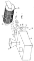
- Figure 1 is a schematic view of one form of the method of the present invention
- Figure 2 is a schematic view of a second form of the method of the present invention.
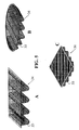
- Figure 3 is an enlarged view of a profile utilized in the method of the present invention to mold the filter medium
- Figure 4 is a perspective view of a second embodiment of the filter medium of the present invention.
- Figure 5 is a perspective view of alternative embodiments of the filter medium of the present invention.
- Extruder 10 includes extruder hopper 11 and a heated barrel containing a screw (not shown). Extruder 10 is in communication with die 12. Die 12 includes feed distribution channel (not shown), die nosepiece 14 and an air manifold 13.
- Air manifold 13 includes air upper air channel 13a and lower air channel 13b. Air manifold 13 supplies high velocity heated air through upper and lower channels 13a, 13b to die nosepiece 14. This high velocity air is generally generated using an air compressor.
- Die nosepiece 14 consists of a wide, hollow, tapered housing having a plurality of rows of openings extending across its length.
- thermoplastic polymer is heated to form a melt.
- any of the thermoplastic polymers, or mixtures thereof, that are known in the art to be useful in the preparation of melt-blown fibers may be used in the method and the filter medium of the present invention to form a melt.
- Suitable thermoplastic polymers include polyethylene, polypropylene, nylon 6, nylon 11, polycarbonate, poly 4-methyl pentene-1, polystyrene, and the like.
- thermoplastic polymer melt then passes into the feed distribution channel, which controls the flow of the melt to die nosepiece 14.
- the melt is next extruded through the openings in nosepiece 14.
- a metering pump typically used in the melt-blown process to provide uniform melt delivery to die 12.
- the heated air streams emerging from upper and lower air channels 13a, 13b of air manifold 13 are directed towards the extruding melt and, upon contact, have the effect of stretching and elongating (i.e., attenuate) the melt emerging from the openings in die nosepiece 14.
- the attenuation of the melt forms a multiplicity of fibers, the size of which depends on several factors which may include, for example, the characteristics of the thermoplastic polymer used and other factors such as temperature, pressure. air velocity, etc.
- the melt-blown thermoplastic fibers are carried by the air streams away from die 12 to laterally spaced collection drum 20.
- Collection drum 20 has surface 22 that defines a plurality of apertures and includes multiple three-dimensional profiles 24 spaced apart from each other on surface 22. Shown in an enlarged view in Fig. 3, profile 24 includes a plurality of apertures in a mesh-like arrangement. Profile 24 also defines folds 25 that extend below surface 22 of collection drum 20. As the heated air streams containing the fibers move towards collection drum 20, the air streams pull in a large amount of surrounding air that cools and solidifies the fibers. These solidified, yet flexible, fibers then get deposited in a random orientation on profile 24 of surface 22. As illustrated, the collection drum 20 rotates in a clockwise direction as the fibers are collected on surface 22. A vacuum may be applied to the inside of collection drum 20 to withdraw the hot air from surface 22.
- Collection drum 20 may be positioned from die nosepiece 14 as appropriate for the desired fiber deposition.
- Profile 24 functions to mold the fibers into filter medium 34 as shown in Fig. 4. Filter medium 34 is then removed from profile 24. Filter medium 34 has folds 35 that correspond with folds 25 of profile 24, and filter medium 34 defines a plurality of pores having a pore size of between three (3) and twelve (12) microns.
- surface 22 of collection drum 20 defines profile 24.
- profile 24 is an integral portion of surface 22 and may not be removed from surface 22. After the fibers are collected on profile 24 and profile 24 molds the fibers into filter medium 34, filter medium 34 is either peeled or stamped from surface 22.
- profile 24 is attached to surface 22 by an adhesive, hook and loop fastener, or the like. After the fibers are collected on profile 24, profile 24 molds the fibers into filter medium 34. Profile 24 may then be removed from surface 22. and filter medium 34 is removed from profile 24. In this form of the present invention, profile 24 may be shaped differently to mold filter medium 34 into different shapes without altering surface 22 of collection drum 22.
- die nosepiece 14 is movable and collection drum 20 is stationary.
- collection drum 20 does not rotate as the fibers are blown from nosepiece 14 and deposited in a random orientation on profile 24 of surface 22.
- both die nosepiece 14 and conveyor 26 are stationary.
- the heated air streams emerging from upper and lower air channels 13a, 13b of air manifold 13 may be appropriately angled towards the extruding melt so as to blow attenuated fibers towards surface 28 of collection drum 20.
- Extruder 10 is both positioned above and vertically spaced apart from conveyor 26.
- thermoplastic polymer granules are fed into extruder hopper 11 and fed to a rotating screw within the heated barrel of extruder 10.
- the rotating of the screw within the heated barrel melts the polymer granules and directs the thermoplastic melt towards die 12.
- the thermoplastic polymer melt then passes into the feed distribution channel and is extruded through the openings in nosepiece 14.
- Nosepiece 14 extends down from die 10 so as to extrude fibers in a downward direction. As the thermoplastic polymer melt is extruded through the openings in die nosepiece 14.
- heated air streams emerge from upper and lower air channels 13a, 13b of air manifold 13 and are directed towards the extruding melt. Upon contact with the melt, the air streams attenuate the melt to form a multiplicity of fibers. The melt-blown thermoplastic fibers are then carried downward to conveyor 26.
- Conveyor 26 has surface 28 that defines a plurality of apertures and includes multiple three-dimensional profiles 24 spaced apart from each other on surface 28.
- the heated air streams containing the fibers move towards conveyor 26 and draw in a large amount of surrounding air that cools and solidifies the fibers as they are deposited in a random orientation on profile 24 of surface 28.
- Conveyor 26 is activated and moves in a westward direction as the fibers are deposited on surface 28. Conveyor 26 may move in an either an eastward or westward direction depending on the placement of extruder 10.
- thermoplastic fibers extruded from die nosepiece 14 cool during their travel from nosepiece 14 to conveyor 26, the fibers maintain a sufficient amount of softness and tackiness so that they will adhere and bond to both each other and to profiles 24.
- Suction box 30 may be applied to the underside of conveyor 26 to withdraw the hot air from surface 28.
- Conveyor 26 may be positioned from nosepiece 14 as appropriate for the desired fiber deposition.
- Profile 24 functions to mold the fibers into filter medium 34 as shown in FIG. 4. Filter medium 34 is then removed from profile 24. Filter medium 34 defines both folds 35 and a plurality of pores having a pore size of between three (3) and twelve (12) microns.
- surface 28 of conveyor 26 defines profile 24. Shown in FIG. 3, profile 24 is an integral portion of surface 28 and may not be removed from surface 28. After the fibers are collected on profile 24 and profile 24 molds the fibers into filter medium 34, filter medium 34 is removed from surface 28.
- profile 24 (FIG. 4) is attached to surface 28 by an adhesive, hook and loop fastener, or the like. After the fibers are collected on profile 24 and profile 24 molds the fibers into filter medium 34, profile 24 may be removed from surface 28. In this form of the present invention, profile 24 may be shaped differently to mold filter medium 34 into different shapes without altering surface 28 of conveyor 26.
- die nosepiece 14 is movable and conveyor 26 is stationary.
- conveyor 26 does not move as the fibers are blown from nosepiece 14 and deposited in a random orientation on profile 24 of surface 28.
- both nosepiece 14 and conveyor 26 are stationary.
- the hot air streams emerging from the air channels 13a, 13b may be appropriately angled towards the extruding melt so as to blow attenuated fibers towards surface 28 of conveyor 26.
- FIG. 5 illustrates alternative embodiments of filter medium 34 formed as a result of the method of the present invention.
- Filter medium 34 is a three-dimensional netting material adapted for use in an IC engine air filter.
- the use of the term "netting" hereinafter refers to a meshed network of fibers. Illustrated in FIG. 5A, filter medium 34 is rectangular in shape. Shown in FIGS. 5B and 5C, filter medium 34 also can be circular or square in shape.
Landscapes
- Engineering & Computer Science (AREA)
- Chemical & Material Sciences (AREA)
- Chemical Kinetics & Catalysis (AREA)
- Textile Engineering (AREA)
- Combustion & Propulsion (AREA)
- Mechanical Engineering (AREA)
- General Engineering & Computer Science (AREA)
- Filtering Materials (AREA)
Abstract
Description
Claims (13)
- A method of making a porous filter medium (34) adapted for use in an internal combustion engine air filter, the method comprising the steps of:heating a thermoplastic polymer to form a melt;extruding the melt through a plurality of openings in a die head (14);directing one or more streams of heated fluid toward the extruding melt to form a multiplicity of fibers and to blow the fibers toward a collection means (20), the collection means having a surface (22) that includes a three-dimensional profile (24);collecting the fibers on the surface of the collection means and utilizing the profile to mold the fibers into the filter medium, the filter medium having at least one fold (35); and removing the filter medium from the profile.
- The method of Claim 1 wherein the filter medium defines a plurality of pores having a pore size of between 3 and 12 microns.
- A process for producing a thermoplastic polymer filter medium (34) adapted for use in an internal combustion air filter, the process comprising the steps of melt-blowing a thermoplastic polymer to form melt-blown fibers, collecting the fibers on a collection means (20) having a surface including a three-dimensional profile (24), utilizing the profile to mold the fibers into the filter medium, the filter medium defining at least one fold (35) and a plurality of pores having a pore size of between 3 and 12 microns, and removing the filter medium from the collection means.
- The process of Claim 3 wherein the step of melt-blowing includes the steps of heating a thermoplastic polymer to form a melt, extruding the melt through a plurality of openings in a die head directing one or more streams of heated fluid toward the extruding melt to form a multiplicity of fibers, and blowing the fibers toward the collection means.
- The method of any one of claims 1 to 4 wherein the surface of the collection means defines the profile, the profile having at least one fold (25).
- The method of any one of claims 1 to 4 wherein at least one profile is removably attached to the surface of the collection means, the profile having at least one fold.
- The method of any preceding claim wherein the collection means is a rotatable drum.
- The method of Claim 7 further including a step of rotating the drum while collecting the fibers.
- The method of any preceding claim wherein the collection means is a conveyor.
- The method of Claim 9 further including a step of activating the conveyor while collecting the fibers.
- The method of Claim 1 or 2, or claim 4, or any one of claims 5 to 10 when dependent on claim 4, wherein the heated fluid is air.
- A porous filter medium (34) said filter medium comprising:a three-dimensional thermoplastic polymer netting material defining at least one fold and defining a plurality of pores having a pore size of between 3 and 12 microns.
- The filter medium of Claim 12 wherein said filter medium is adapted for use in an internal combustion engine air filter.
Applications Claiming Priority (2)
| Application Number | Priority Date | Filing Date | Title |
|---|---|---|---|
| US379467 | 2003-03-03 | ||
| US10/379,467 US6932923B2 (en) | 2003-03-03 | 2003-03-03 | Method of making a melt-blown filter medium for use in air filters in internal combustion engines and product |
Publications (2)
| Publication Number | Publication Date |
|---|---|
| EP1455080A2 true EP1455080A2 (en) | 2004-09-08 |
| EP1455080A3 EP1455080A3 (en) | 2008-10-08 |
Family
ID=32824770
Family Applications (1)
| Application Number | Title | Priority Date | Filing Date |
|---|---|---|---|
| EP04251190A Withdrawn EP1455080A3 (en) | 2003-03-03 | 2004-03-02 | Method of making a melt-blown filter medium for use in filters in internal combustion engines and product |
Country Status (4)
| Country | Link |
|---|---|
| US (1) | US6932923B2 (en) |
| EP (1) | EP1455080A3 (en) |
| JP (1) | JP4092297B2 (en) |
| CN (1) | CN100368618C (en) |
Cited By (5)
| Publication number | Priority date | Publication date | Assignee | Title |
|---|---|---|---|---|
| US5855264A (en) * | 1996-02-12 | 1999-01-05 | Labavia Sge | Vehicle transmission system fitted with an electrical retarder |
| FR2921941A1 (en) * | 2007-10-03 | 2009-04-10 | Charles Weiskopf | DEVICE FOR MANUFACTURING A TABLET OF NON-WOVEN FIBERS |
| EP2660377A1 (en) * | 2012-05-03 | 2013-11-06 | Chen-Cheng Huang | Method of making a double-sided embossed non-woven fabric |
| US9175428B2 (en) | 2012-04-30 | 2015-11-03 | Chen-Cheng Huang | Method of making a double-sided embossed non-woven fabric |
| DE102019208275A1 (en) * | 2019-06-06 | 2020-12-10 | Adidas Ag | Method for providing a nonwoven fabric |
Families Citing this family (16)
| Publication number | Priority date | Publication date | Assignee | Title |
|---|---|---|---|---|
| US7959714B2 (en) | 2007-11-15 | 2011-06-14 | Cummins Filtration Ip, Inc. | Authorized filter servicing and replacement |
| US8114183B2 (en) * | 2005-09-20 | 2012-02-14 | Cummins Filtration Ip Inc. | Space optimized coalescer |
| US7674425B2 (en) * | 2005-11-14 | 2010-03-09 | Fleetguard, Inc. | Variable coalescer |
| US7828869B1 (en) | 2005-09-20 | 2010-11-09 | Cummins Filtration Ip, Inc. | Space-effective filter element |
| US20070062886A1 (en) * | 2005-09-20 | 2007-03-22 | Rego Eric J | Reduced pressure drop coalescer |
| US8231752B2 (en) * | 2005-11-14 | 2012-07-31 | Cummins Filtration Ip Inc. | Method and apparatus for making filter element, including multi-characteristic filter element |
| US7754041B2 (en) * | 2006-07-31 | 2010-07-13 | 3M Innovative Properties Company | Pleated filter with bimodal monolayer monocomponent media |
| CN102149859B (en) * | 2009-06-25 | 2015-08-26 | 北京阿迈特医疗器械有限公司 | For the preparation of the method and apparatus of three-dimensional porous tubular bracket |
| CN103380242B (en) * | 2011-01-28 | 2016-03-02 | 特布乐丝株式会社 | The melt spraying non-woven fabrics be made up of superfine fibre, the manufacture method of this melt spraying non-woven fabrics and the device for the manufacture of this melt spraying non-woven fabrics |
| US9278301B2 (en) | 2013-08-16 | 2016-03-08 | 3M Innovative Properties Company | Nestable framed pleated air filter and method of making |
| US9174159B2 (en) | 2013-08-16 | 2015-11-03 | 3M Innovative Properties Company | Framed pleated air filter with upstream bridging filaments |
| US20150182895A1 (en) * | 2013-12-31 | 2015-07-02 | Bha Altair, Llc | Process for making rigid porous plastic tubular filters |
| WO2020081437A1 (en) | 2018-10-16 | 2020-04-23 | Cummins Filtration Ip, Inc. | Adhesive alloys and filter medias including such adhesive alloys |
| CN112746393A (en) * | 2020-12-30 | 2021-05-04 | 宜昌市欣龙卫生材料有限公司 | Melt blown fiber web forming system |
| CN115110207A (en) * | 2022-07-18 | 2022-09-27 | 欣龙控股(集团)股份有限公司 | A kind of 3D meltblown cloth and preparation method and application |
| CN118531561A (en) * | 2024-05-24 | 2024-08-23 | 浙江百浩工贸有限公司 | Ultrafine fiber material with folded three-dimensional structure and preparation method thereof |
Family Cites Families (22)
| Publication number | Priority date | Publication date | Assignee | Title |
|---|---|---|---|---|
| US2335757A (en) * | 1939-10-13 | 1943-11-30 | Electric Storage Battery Co | Storage battery retainer |
| US4177312A (en) * | 1978-05-08 | 1979-12-04 | Akzona Inc. | Matting article |
| US4631077A (en) * | 1985-03-26 | 1986-12-23 | Pipercrosslimited | Foam plastic air filter |
| US4676807A (en) * | 1985-07-05 | 1987-06-30 | Pall Corporation | Process for removal of liquid aerosols from gaseous streams |
| US4824451A (en) * | 1985-12-31 | 1989-04-25 | Kimberly-Clark Corporation | Melt-blown filter medium |
| US4925601A (en) * | 1988-01-19 | 1990-05-15 | Kimberly-Clark Corporation | Method for making melt-blown liquid filter medium |
| CA2027687C (en) * | 1989-11-14 | 2002-12-31 | Douglas C. Sundet | Filtration media and method of manufacture |
| US5271883A (en) * | 1990-06-18 | 1993-12-21 | Kimberly-Clark Corporation | Method of making nonwoven web with improved barrier properties |
| US5306321A (en) * | 1992-07-07 | 1994-04-26 | Donaldson Company, Inc. | Layered air filter medium having improved efficiency and pleatability |
| US5407739A (en) * | 1993-07-28 | 1995-04-18 | The Dow Chemical Company | Ignition resistant meltbrown or spunbonded insulation material |
| JP3301227B2 (en) * | 1994-07-28 | 2002-07-15 | 株式会社デンソー | Filter manufacturing method |
| GB9609811D0 (en) * | 1996-05-10 | 1996-07-17 | Web Dynamics Ltd | A process for producing meltblown polyolefin fibres for mechanical filtration |
| US5891482A (en) * | 1996-07-08 | 1999-04-06 | Aaf International | Melt blowing apparatus for producing a layered filter media web product |
| AU2025900A (en) * | 1998-11-17 | 2000-06-05 | Eldim, Inc. | Method and apparatus for manufacturing non-woven articles |
| US6165242A (en) * | 1999-03-27 | 2000-12-26 | Aaf International, Inc | Pleated filter media with crest spacers and method of making |
| US6521555B1 (en) * | 1999-06-16 | 2003-02-18 | First Quality Nonwovens, Inc. | Method of making media of controlled porosity and product thereof |
| DE60041154D1 (en) * | 1999-10-29 | 2009-01-29 | Hollingsworth & Vose Co | FILTER MATERIAL |
| JP2002011311A (en) * | 2000-04-28 | 2002-01-15 | Toyoda Spinning & Weaving Co Ltd | Production method for filter material, and filter material |
| JP2002186809A (en) * | 2000-12-20 | 2002-07-02 | Toyoda Spinning & Weaving Co Ltd | Filter and method for manufacturing the same |
| JP4595206B2 (en) * | 2001-01-24 | 2010-12-08 | トヨタ紡織株式会社 | Filter and manufacturing method thereof |
| JP4670166B2 (en) * | 2001-03-21 | 2011-04-13 | トヨタ紡織株式会社 | Filter manufacturing method |
| JP4631185B2 (en) * | 2001-03-13 | 2011-02-16 | トヨタ紡織株式会社 | Filter and manufacturing method thereof |
-
2003
- 2003-03-03 US US10/379,467 patent/US6932923B2/en not_active Expired - Fee Related
-
2004
- 2004-03-02 EP EP04251190A patent/EP1455080A3/en not_active Withdrawn
- 2004-03-02 JP JP2004057121A patent/JP4092297B2/en not_active Expired - Lifetime
- 2004-03-03 CN CNB2004100069874A patent/CN100368618C/en not_active Expired - Fee Related
Cited By (6)
| Publication number | Priority date | Publication date | Assignee | Title |
|---|---|---|---|---|
| US5855264A (en) * | 1996-02-12 | 1999-01-05 | Labavia Sge | Vehicle transmission system fitted with an electrical retarder |
| FR2921941A1 (en) * | 2007-10-03 | 2009-04-10 | Charles Weiskopf | DEVICE FOR MANUFACTURING A TABLET OF NON-WOVEN FIBERS |
| US9175428B2 (en) | 2012-04-30 | 2015-11-03 | Chen-Cheng Huang | Method of making a double-sided embossed non-woven fabric |
| EP2660377A1 (en) * | 2012-05-03 | 2013-11-06 | Chen-Cheng Huang | Method of making a double-sided embossed non-woven fabric |
| DE102019208275A1 (en) * | 2019-06-06 | 2020-12-10 | Adidas Ag | Method for providing a nonwoven fabric |
| DE102019208275B4 (en) | 2019-06-06 | 2025-03-13 | Adidas Ag | Method for providing a nonwoven fabric |
Also Published As
| Publication number | Publication date |
|---|---|
| EP1455080A3 (en) | 2008-10-08 |
| CN1570244A (en) | 2005-01-26 |
| US20040172930A1 (en) | 2004-09-09 |
| JP4092297B2 (en) | 2008-05-28 |
| US6932923B2 (en) | 2005-08-23 |
| CN100368618C (en) | 2008-02-13 |
| JP2004270695A (en) | 2004-09-30 |
Similar Documents
| Publication | Publication Date | Title |
|---|---|---|
| US6932923B2 (en) | Method of making a melt-blown filter medium for use in air filters in internal combustion engines and product | |
| KR940004708B1 (en) | Fusion Blown Material with Depth Fiber Size Gradient | |
| JP5654356B2 (en) | Composite nonwoven web and method for making and using the same | |
| JP5819832B2 (en) | Nozzles, apparatus, systems and methods for forming nanofibrous webs and articles made by this method | |
| EP0888466B1 (en) | Process and apparatus for producing non-woven webs | |
| US5993943A (en) | Oriented melt-blown fibers, processes for making such fibers and webs made from such fibers | |
| EP2376693B1 (en) | Patterned spunbond fibrous webs and methods of making and using the same | |
| JP2825514B2 (en) | Oriented melt-sprayed fiber, method for producing the same and web thereof | |
| KR100995213B1 (en) | Nonwoven Amorphous Fiber Web and Method of Making the Same | |
| JPH03174008A (en) | Method for production of synthetic yarn and/or fiber in the course of manufacture of spinning fleece from thermoplastic plastic and spinning nozzle unit | |
| JPS6099058A (en) | Composite fiber and its web | |
| WO1999028122A1 (en) | Nonwoven fabrics formed from ribbon-shaped fibers and method and apparatus for making the same | |
| CA2082058A1 (en) | Nonwoven filter and method of manufacture | |
| JPH0813309A (en) | Melt blow nonwoven fabric and its production | |
| KR20210158865A (en) | Method for producing a foldable textile fabric with electrostatically charged fibers, and a foldable textile fabric | |
| CA2257514C (en) | Method of and apparatus for producing a composite web | |
| CA2408304C (en) | Process and device for the transport of continuous moldings without tensile stress | |
| JPH0596110A (en) | Cylindrical filter and its production | |
| JP2586125B2 (en) | Long-fiber nonwoven fabric and its manufacturing method | |
| EP0581909B1 (en) | Non-woven Fabric | |
| JP2586126B2 (en) | Long-fiber nonwoven fabric and method for producing the same | |
| JPH1119435A (en) | Cylindrical filter composed of extra fine conjugate fiber nonwoven fabric and its production | |
| JP2007500629A (en) | Three-dimensional film and manufacturing method thereof | |
| JP2020165013A (en) | Method of manufacturing fiber non-woven fabric | |
| DE20308475U1 (en) | Device for producing spunbonded nonwovens from filaments |
Legal Events
| Date | Code | Title | Description |
|---|---|---|---|
| PUAI | Public reference made under article 153(3) epc to a published international application that has entered the european phase |
Free format text: ORIGINAL CODE: 0009012 |
|
| AK | Designated contracting states |
Kind code of ref document: A2 Designated state(s): AT BE BG CH CY CZ DE DK EE ES FI FR GB GR HU IE IT LI LU MC NL PL PT RO SE SI SK TR |
|
| AX | Request for extension of the european patent |
Extension state: AL HR LT LV MK |
|
| RAP1 | Party data changed (applicant data changed or rights of an application transferred) |
Owner name: PUROLATOR FILTERS NA LLC |
|
| PUAL | Search report despatched |
Free format text: ORIGINAL CODE: 0009013 |
|
| AK | Designated contracting states |
Kind code of ref document: A3 Designated state(s): AT BE BG CH CY CZ DE DK EE ES FI FR GB GR HU IE IT LI LU MC NL PL PT RO SE SI SK TR |
|
| AX | Request for extension of the european patent |
Extension state: AL LT LV MK |
|
| RIC1 | Information provided on ipc code assigned before grant |
Ipc: B01D 29/01 20060101ALI20080904BHEP Ipc: D04H 3/16 20060101ALI20080904BHEP Ipc: D04H 1/72 20060101ALI20080904BHEP Ipc: D04H 3/07 20060101ALI20080904BHEP Ipc: D04H 3/03 20060101ALI20080904BHEP Ipc: D04H 1/56 20060101ALI20080904BHEP Ipc: F02M 35/02 20060101AFI20040622BHEP |
|
| AKX | Designation fees paid | ||
| REG | Reference to a national code |
Ref country code: DE Ref legal event code: 8566 |
|
| STAA | Information on the status of an ep patent application or granted ep patent |
Free format text: STATUS: THE APPLICATION IS DEEMED TO BE WITHDRAWN |
|
| 18D | Application deemed to be withdrawn |
Effective date: 20090409 |