EP1454829A1 - Cigarette packing method and machine - Google Patents
Cigarette packing method and machine Download PDFInfo
- Publication number
- EP1454829A1 EP1454829A1 EP04100913A EP04100913A EP1454829A1 EP 1454829 A1 EP1454829 A1 EP 1454829A1 EP 04100913 A EP04100913 A EP 04100913A EP 04100913 A EP04100913 A EP 04100913A EP 1454829 A1 EP1454829 A1 EP 1454829A1
- Authority
- EP
- European Patent Office
- Prior art keywords
- relative
- packet
- folding
- contrast member
- lateral wall
- Prior art date
- Legal status (The legal status is an assumption and is not a legal conclusion. Google has not performed a legal analysis and makes no representation as to the accuracy of the status listed.)
- Granted
Links
- 238000000034 method Methods 0.000 title claims abstract description 13
- 235000019504 cigarettes Nutrition 0.000 title claims abstract description 12
- 238000012856 packing Methods 0.000 title claims abstract description 12
- 239000003292 glue Substances 0.000 claims description 9
- 238000005096 rolling process Methods 0.000 claims description 4
- 238000011144 upstream manufacturing Methods 0.000 claims description 3
- 230000003213 activating effect Effects 0.000 claims 2
- 230000003068 static effect Effects 0.000 claims 2
- 230000002093 peripheral effect Effects 0.000 claims 1
- 239000004831 Hot glue Substances 0.000 description 3
- 241000208125 Nicotiana Species 0.000 description 1
- 235000002637 Nicotiana tabacum Nutrition 0.000 description 1
- 230000006835 compression Effects 0.000 description 1
- 238000007906 compression Methods 0.000 description 1
Images

Classifications
-
- B—PERFORMING OPERATIONS; TRANSPORTING
- B65—CONVEYING; PACKING; STORING; HANDLING THIN OR FILAMENTARY MATERIAL
- B65B—MACHINES, APPARATUS OR DEVICES FOR, OR METHODS OF, PACKAGING ARTICLES OR MATERIALS; UNPACKING
- B65B19/00—Packaging rod-shaped or tubular articles susceptible to damage by abrasion or pressure, e.g. cigarettes, cigars, macaroni, spaghetti, drinking straws or welding electrodes
- B65B19/02—Packaging cigarettes
- B65B19/22—Wrapping the cigarettes; Packaging the cigarettes in containers formed by folding wrapping material around formers
- B65B19/223—Wrapping the cigarettes; Packaging the cigarettes in containers formed by folding wrapping material around formers in a curved path; in a combination of straight and curved paths, e.g. on rotary tables or other endless conveyors
- B65B19/225—Wrapping the cigarettes; Packaging the cigarettes in containers formed by folding wrapping material around formers in a curved path; in a combination of straight and curved paths, e.g. on rotary tables or other endless conveyors the conveyors having continuous movement
Definitions
- the present invention relates to a cigarette packing method and machine.
- cigarette packing machines comprising an output wheel which rotates about a respective axis to feed a number of gripping heads along a folding path.
- Each gripping head is engaged by and retains a respective packet of cigarettes comprising two minor longitudinal lateral walls, each of which is defined by an outer longitudinal tab and an inner longitudinal tab superimposed and connected integrally to each other.
- each gripping head receives the relative packet with the relative outer longitudinal tabs in an open position, and comprises two folding wings, each of which is movable, at a folding station extending along a portion of the folding path, from an initial open position supporting the relative outer longitudinal tab in the open position, and a final closed position to fold the relative outer longitudinal tab into a closed position contacting the relative inner longitudinal tab.
- a cigarette packing method as claimed in Claim 1 and, preferably, in any one of the following Claims depending directly or indirectly on Claim 1.
- a cigarette packing machine as claimed in Claim 8 and, preferably, in any one of the following Claims depending directly or indirectly on Claim 8.
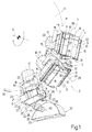
- Number 1 in Figure 1 indicates as a whole a cigarette packing machine, an output portion 2 of which comprises an output wheel 3, in turn comprising a powered central disk 4 which rotates continuously (clockwise in Figure 1) about a respective central axis 5.
- Output wheel 3 also comprises a number of gripping heads 6 equally spaced along the periphery of central disk 4, and for receiving respective packets 7 of cigarettes, still partly open, at an input station (not shown), for feeding respective packets 7 along a circular folding path P to an output station (not shown), and for completing closure of respective packets 7 as they are fed along folding path P.
- Each packet 7 is a rigid, hinged-lid packet substantially in the form of a rectangular parallelepiped, and having a longitudinal axis 8; a front major lateral wall 9 and a rear major lateral wall 10 parallel to each other and to longitudinal axis 8; two minor lateral walls 11 parallel to each other and to longitudinal axis 8 and perpendicular to major lateral walls 9 and 10; and two end walls 12 and 13.
- Each minor lateral wall 11 is defined by an inner longitudinal tab 14 connected to a lateral edge of the relative rear major lateral wall 10, and by an outer longitudinal tab 15 connected to a lateral edge of the relative front major lateral wall 9.
- Tabs 14 and 15 are superimposed and glued to each other with the interposition of a layer of glue 16, which may be defined by hot glue, cold glue, or, as in the example shown, by hot and cold glue.
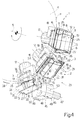
- each gripping head 6 comprises a tubular shaft 17 connecting relative gripping head 6 to central disk 4, and fitted integrally on its outer end with a substantially rectangular end plate 18, from which projects outwards a further tubular shaft 19 coaxial with relative tubular shaft 17 and closed at its outer end by a substantially rectangular plate 20 parallel to end plate 18.
- Tubular shafts 17 and 19 house a known mechanism (not shown) for controlling the angular position of two wings 21, each of which has an end tooth 22 (dispensed with in a variation not shown) facing the other wing 21, and is hinged to a lateral edge of plate 20 to rotate - about a respective axis 24 and as relative gripping head 6 travels through a folding station 23 extending along a portion of folding path P - between an open position (on the right in Figure 1) in which wing 21 is substantially coplanar with plate 20, and a normal closed position (on the left in Figure 1) in which wing 21 is perpendicular to plate 20.
- wings 21 and respective end teeth 22 define, together with relative plate 20, a seat 25 for receiving and retaining a relative packet 7 positioned with longitudinal axis 8 parallel to axes 24, with front major lateral wall 9 contacting plate 20, and with rear major lateral wall 10 facing outwards with respect to central disk 4.
- Two diametrically opposite jaws 26 are hinged to the outside of tubular shaft 17, each has a transverse end tooth 27, and each is rotated - by a known actuating device (not shown) carried by central disk 4, and in a plane parallel to axes 24 and perpendicular to the plane of plate 20 - between an open position and a closed position closing a respective end of relative seat 25.
- each gripping head 6 travels along a portion of folding path P upstream from folding station 23 with wings 21 in the open position, and with jaws 26 in the closed position to retain inside relative seat 25 a respective packet 7 positioned with longitudinal axis 8 parallel to a travelling direction 28 of relative gripping head 6 along folding path P, with relative front major lateral wall 9 contacting plate 20, and with relative outer longitudinal tabs 15 open and contacting respective wings 21.
- gripping head 6 and relative packet 7 are fed through a gumming station 29, where two hot-glue gumming devices 30, located in fixed positions on opposite sides of folding path P, and two cold-glue gumming device 31, also located in fixed positions on opposite sides of folding path P, deposit spots of hot and cold glue respectively to form a layer of glue 16 on the inner surface of each of outer longitudinal tabs 15, still in the open position contacting relative wings 21, which are moved into the closed position as they subsequently travel through folding station 23.
- Closure of wings 21 provides, on the one hand, for completing closure of packet 7, and, on the other, if teeth 22 are provided, for further connecting packet 7 to gripping head 6, by teeth 22, as wings 21 close, engaging rear major lateral wall 10 of packet 7 to further secure packet 7 on plate 20.
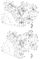
- gripping head 6 is accompanied along folding path P by a contrast member 32 fitted to a contrast device 33 and for preventing major lateral walls 9 and 10, and in particular rear major lateral wall 10, from bulging outwards as a result of the lateral compression applied by wings 21 as they are closed.
- contrast device 33 comprises a powered shaft 34 mounted to rotate (anticlockwise in Figures 2 and 3) about a respective axis 35 extending parallel to axis 5 and outside folding path P.
- Shaft 34 is fitted with a disk 36, in turn fitted with a number of contrast members 32 (three in the example shown, but which may differ in number) equally spaced about axis 35, and each comprising a substantially rectangular plate 37, which is substantially the same width as rear major lateral wall 10, if no teeth 22 are provided, or, conversely, is approximately as wide as but no wider than the distance between the facing ends of end teeth 22 of wings 21 of gripping head 6 when wings 21 are in the closed position.
- Each plate 37 is also substantially the same length as major lateral walls 9 and 10, and has, along each minor lateral edge, a recess 38 for receiving, in use, the end tooth 27 of a respective jaw 26 of respective gripping head 6.
- Each contrast member 32 also comprises a hinge 39 connecting relative plate 37 to disk 36 to enable plate 37 to rotate with respect to disk 36 about a respective axis 40 parallel to axis 35.
- the angular position of each plate 37 about relative axis 40 and with respect to disk 36 is controlled by a cam device 41 comprising a fixed annular track 42 extending about axis 35 and travelled, in use, by cam followers 43, each of which is fitted to a respective lever 44 integral with a respective plate 37.
- shaft 34 is operated synchronously with output wheel 3, so that each gripping head 6 is accompanied, as it travels through folding station 23, by a respective contrast member 32, the plate 37 of which is positioned contacting rear major lateral wall 10 of relative packet 7 to press packet 7 against relative plate 20, and rotates about axis 35 and also about relative axis 40 under the control of cam device 41, so as to remain parallel to plate 20 for as long as it takes for wings 21 to fold relative outer longitudinal tabs 15 squarely, and so prevent relative rear major lateral wall 10 from bulging outwards.
- a contrast device 45 comprising a powered shaft 46, which is mounted at folding station 23 to rotate about a respective axis 47 parallel to axis 5 and outside folding path P.
- Shaft 46 is fitted with a substantially rectangular plate 48 perpendicular to axis 47 and having, at each longitudinal end (or, in a variation not shown, at only one longitudinal end), an enlarged head 49 defining a respective contrast member.
- each head 49 is bounded externally by an outwardly convex rolling surface 50 which, as shaft 46 rotates and a gripping head 6 and a relative packet 7 travel through folding station 23, rolls on rear major lateral wall 10 of packet 7 to prevent rear major lateral wall 10 from deforming outwards.
Abstract
Description
Claims (16)
- A method of packing cigarettes in packets (7) having two major lateral walls (9, 10); and two minor lateral walls (11), each defined by an inner longitudinal tab (14) and an outer longitudinal tab (15) superimposed and integral with each other; the method comprising the steps of feeding said packets (7) successively along a folding path (P) extending through a folding station (23), each packet (7) being fed along the folding path (P) by a relative gripping head (6) for retaining the relative packet (7) by the ends and with the outer longitudinal tabs (15) of the packet in an open position, detached from the respective inner longitudinal tabs (14), and supported, in said open position, by respective folding wings (21) carried by the gripping head (6); and moving said folding wings (21) of each gripping head (6), at said folding station (23), to fold each outer longitudinal tab (15) into a closed position contacting the relative inner longitudinal tab (14); and being characterized by comprising the further step of bringing and keeping an external contrast member (32; 49) into/in contact with a substantially free said major lateral wall (10), facing outwards with respect to the relative said gripping head (6), of each packet (7) during at least part of the time the packet (7) travels through said folding station (23).
- A method as claimed in Claim 1, wherein said folding path (P) extends through a gumming station (29) upstream from said folding station (23); glue being fed between each outer longitudinal tab (15) and the relative inner longitudinal tab (14) at said gumming station (29).
- A method as claimed in Claim 1 or 2, wherein said contact between the contrast member (32) and the relative said major lateral wall (10) is a static contact with zero relative speed between the contrast member (32) and the relative packet (7).
- A method as claimed in Claim 3, wherein said contrast member (32) is rotated about a first axis (35), outside said folding path (P), to travel through said folding station (23) synchronously with a relative said gripping head (6), and is oscillated about a second axis (40), parallel to said first axis (35), to remain constantly parallel to the relative said major lateral wall (10) inside said folding station (23).
- A method as claimed in any one of Claims 1 to 4, wherein said contrast member (32) comprises a flat plate (37) .
- A method as claimed in Claim 1 or 2, wherein said contact between the contrast member (49) and the relative said major lateral wall (10) is a dynamic contact with relative movement between the contrast member (49) and the relative packet (7).
- A method as claimed in Claim 6, wherein said relative movement is a rolling movement of said contrast member (49) on the relative said major lateral wall (10).
- A machine for packing cigarettes in packets (7) having two major lateral walls (9, 10); and two minor lateral walls (11), each defined by an inner longitudinal tab (14) and an outer longitudinal tab (15) superimposed and integral with each other; the machine comprising conveying means (3) for feeding said packets (7) successively along a folding path (P) extending through a folding station (23); said conveying means (3) comprising a succession of gripping heads (6), each of which comprises gripping means (26) for retaining the relative packet (7) by the ends and with the outer longitudinal tabs (15) of the packet in an open position detached from the respective inner longitudinal tabs (14), and two folding wings (21), each of which is movable, at said folding station (23), from an initial open position supporting the relative outer longitudinal tab (15) in the open position, to a final closed position to fold the relative outer longitudinal tab (15) into a closed position contacting the relative inner longitudinal tab (14); and being characterized by comprising at least one external contrast member (32; 49), and actuating means for bringing and keeping said contrast member (32; 49) into/in contact with a substantially free said major lateral wall (10), facing outwards with respect to the relative said gripping head (6), of each packet (7) during at least part of the time the packet (7) travels through said folding station (23).
- A machine as claimed in Claim 8, and also comprising gumming means located at a gumming station (29) located along said folding path (P) and upstream from said folding station (23) to feed glue between each outer longitudinal tab (15) and the relative inner longitudinal tab (14).
- A machine as claimed in Claim 8 or 9, and comprising a contrast device (33) for activating said contrast member (32) so that said contact between the contrast member (32; 49) and the relative said major lateral wall (10) is a static contact with zero relative speed between the contrast member (32) and the relative packet (7).
- A machine as claimed in Claim 10, wherein said contrast device (33) comprises a powered shaft (34) mounted to rotate about a respective axis (35) crosswise to and extending outside the folding path (P); a support (36) integral with said shaft (34); a hinge (39) interposed between said contrast member (32) and said support (36) to enable the contrast member (32) to rotate with respect to said support (36) about a second axis (40) parallel to said first axis (35); and control means (41) for controlling an angular position of said contrast member (32) about said second axis (40) according to a given law.
- A machine as claimed in Claim 11, wherein said contrast member (32) comprises a flat plate (37) which is brought into contact with said major lateral wall (10) of a relative said packet (7).
- A machine as claimed in Claim 11 or 12, wherein said control means (41) comprise a cam device, in turn comprising a fixed annular track (42) extending about said first axis (35), and cam follower means (43) engaging said annular track (42) and connected to said contrast member (32).
- A machine as claimed in Claim 8 or 9, and comprising a contrast device (45) for activating said contrast member (49) so that said contact between the contrast member (49) and the relative said major lateral wall (10) is a dynamic contact with relative movement between the contrast member (49) and the relative packet (7).
- A machine as claimed in Claim 14, wherein said relative movement is a rolling movement of said contrast member (49) on the relative said major lateral wall (10).
- A machine as claimed in Claim 14 or 15, wherein said contrast device (45) comprises a powered shaft (46) mounted at the folding station (23) to rotate about a respective axis (47) extending crosswise to and outside said folding path (P); and a plate (48) fitted to said shaft (46) and having at least one enlarged peripheral head (49), which defines said contrast member (49) and is bounded externally by a rolling surface (50) which rolls on said major lateral wall (10) of a relative said packet (7) travelling through said folding station (23).
Applications Claiming Priority (2)
| Application Number | Priority Date | Filing Date | Title |
|---|---|---|---|
| IT000123A ITBO20030123A1 (en) | 2003-03-06 | 2003-03-06 | METHOD AND MACHINE FOR THE PACKAGING OF CIGARETTES |
| ITBO20030123 | 2003-03-06 |
Publications (2)
| Publication Number | Publication Date |
|---|---|
| EP1454829A1 true EP1454829A1 (en) | 2004-09-08 |
| EP1454829B1 EP1454829B1 (en) | 2007-10-31 |
Family
ID=32800661
Family Applications (1)
| Application Number | Title | Priority Date | Filing Date |
|---|---|---|---|
| EP04100913A Expired - Lifetime EP1454829B1 (en) | 2003-03-06 | 2004-03-05 | Cigarette packing method and machine |
Country Status (7)
| Country | Link |
|---|---|
| US (1) | US6968667B2 (en) |
| EP (1) | EP1454829B1 (en) |
| JP (1) | JP4444696B2 (en) |
| CN (1) | CN100377970C (en) |
| AT (1) | ATE376958T1 (en) |
| DE (1) | DE602004009719T2 (en) |
| IT (1) | ITBO20030123A1 (en) |
Cited By (3)
| Publication number | Priority date | Publication date | Assignee | Title |
|---|---|---|---|---|
| WO2009156135A1 (en) | 2008-06-26 | 2009-12-30 | Focke & Co. (Gmbh & Co. Kg). | Method and device for the production of packages |
| EP2234891B1 (en) | 2008-01-21 | 2016-03-23 | Focke & Co. (GmbH & Co. KG) | Method for the production of packages for cigarettes |
| IT201900000545A1 (en) * | 2019-01-14 | 2020-07-14 | Gd Spa | Process and equipment for packaging products in box-shaped packages |
Families Citing this family (4)
| Publication number | Priority date | Publication date | Assignee | Title |
|---|---|---|---|---|
| ITBO20040498A1 (en) * | 2004-08-03 | 2004-11-03 | Azionaria Costruzioni Acma Spa | DEVICE FOR THE FOLDING OF COVERS OF HARD PACKAGES IN MACHINES FOR THE PACKAGING OF THESE PACKAGES AND INCORPORATING MACHINE OF THIS DEVICE |
| ITBO20060168A1 (en) * | 2006-03-10 | 2006-06-09 | Gd Spa | WRAPPING WHEEL. |
| CN108945621A (en) * | 2018-08-06 | 2018-12-07 | 浙江武义博德机械有限公司 | A kind of lock body automatic box packing device |
| IT202100028871A1 (en) * | 2021-11-15 | 2022-02-15 | Ima Spa | APPARATUS AND PROCEDURE FOR PACKAGING PACKAGES OF SMOKING ITEMS. |
Citations (4)
| Publication number | Priority date | Publication date | Assignee | Title |
|---|---|---|---|---|
| EP0340526A1 (en) * | 1988-05-05 | 1989-11-08 | Focke & Co. (GmbH & Co.) | Packaging machine for hinged-lid boxes |
| EP0741081A2 (en) * | 1995-05-05 | 1996-11-06 | G.D Societa' Per Azioni | Method and machine for packing products and subsequent drying of the packages |
| EP1145958A1 (en) * | 2000-04-10 | 2001-10-17 | G. D Societa per Azioni | Method and machine for producing hinged-lid packets of cigarettes |
| EP1321364A1 (en) * | 2001-12-18 | 2003-06-25 | G.D Societ Per Azioni | Cigarette packing machine |
Family Cites Families (3)
| Publication number | Priority date | Publication date | Assignee | Title |
|---|---|---|---|---|
| GB1467429A (en) * | 1973-09-05 | 1977-03-16 | Schmermund A | Method and apparatus for producing a container |
| US4034655A (en) * | 1973-09-05 | 1977-07-12 | Alfred Schmermund | Method and apparatus for producing a container |
| IT1304032B1 (en) * | 1998-07-14 | 2001-03-02 | Gd Spa | METHOD AND MACHINE FOR WRAPPING A PRODUCT. |
-
2003
- 2003-03-06 IT IT000123A patent/ITBO20030123A1/en unknown
-
2004
- 2004-03-05 AT AT04100913T patent/ATE376958T1/en not_active IP Right Cessation
- 2004-03-05 US US10/794,765 patent/US6968667B2/en not_active Expired - Fee Related
- 2004-03-05 EP EP04100913A patent/EP1454829B1/en not_active Expired - Lifetime
- 2004-03-05 DE DE602004009719T patent/DE602004009719T2/en not_active Expired - Lifetime
- 2004-03-08 JP JP2004064474A patent/JP4444696B2/en not_active Expired - Fee Related
- 2004-03-08 CN CNB2004100064620A patent/CN100377970C/en not_active Expired - Fee Related
Patent Citations (4)
| Publication number | Priority date | Publication date | Assignee | Title |
|---|---|---|---|---|
| EP0340526A1 (en) * | 1988-05-05 | 1989-11-08 | Focke & Co. (GmbH & Co.) | Packaging machine for hinged-lid boxes |
| EP0741081A2 (en) * | 1995-05-05 | 1996-11-06 | G.D Societa' Per Azioni | Method and machine for packing products and subsequent drying of the packages |
| EP1145958A1 (en) * | 2000-04-10 | 2001-10-17 | G. D Societa per Azioni | Method and machine for producing hinged-lid packets of cigarettes |
| EP1321364A1 (en) * | 2001-12-18 | 2003-06-25 | G.D Societ Per Azioni | Cigarette packing machine |
Cited By (6)
| Publication number | Priority date | Publication date | Assignee | Title |
|---|---|---|---|---|
| EP2234891B1 (en) | 2008-01-21 | 2016-03-23 | Focke & Co. (GmbH & Co. KG) | Method for the production of packages for cigarettes |
| WO2009156135A1 (en) | 2008-06-26 | 2009-12-30 | Focke & Co. (Gmbh & Co. Kg). | Method and device for the production of packages |
| DE102008029929A1 (en) | 2008-06-26 | 2009-12-31 | Focke & Co.(Gmbh & Co. Kg) | Method and device for producing packages |
| IT201900000545A1 (en) * | 2019-01-14 | 2020-07-14 | Gd Spa | Process and equipment for packaging products in box-shaped packages |
| EP3680184A1 (en) * | 2019-01-14 | 2020-07-15 | G.D S.p.A. | A method and apparatus for packaging products in box-shaped packages |
| EP3680184B1 (en) | 2019-01-14 | 2021-09-01 | G.D S.p.A. | A method and apparatus for packaging products in box-shaped packages |
Also Published As
| Publication number | Publication date |
|---|---|
| ITBO20030123A1 (en) | 2004-09-07 |
| ATE376958T1 (en) | 2007-11-15 |
| US20040231297A1 (en) | 2004-11-25 |
| DE602004009719T2 (en) | 2008-08-28 |
| DE602004009719D1 (en) | 2007-12-13 |
| EP1454829B1 (en) | 2007-10-31 |
| US6968667B2 (en) | 2005-11-29 |
| CN1535898A (en) | 2004-10-13 |
| CN100377970C (en) | 2008-04-02 |
| JP2004269055A (en) | 2004-09-30 |
| JP4444696B2 (en) | 2010-03-31 |
Similar Documents
| Publication | Publication Date | Title |
|---|---|---|
| US6322486B1 (en) | Method of and apparatus for folding flaps on blanks of packets for rod-shaped smokers' products | |
| US6789370B2 (en) | Cigarette packing machine | |
| JPH10194219A (en) | Pocket wrapping method and its device | |
| EP1452448B1 (en) | Method of producing soft packets of cigarettes | |
| US5755080A (en) | Method and machine for packing products | |
| US6968667B2 (en) | Cigarette packing method and machine | |
| US6035612A (en) | Product wrapping method and machine | |
| ITBO970150A1 (en) | BENDING METHOD FOR THE FORMATION OF A SEALED TUBE ENVELOPE | |
| EP1502861A1 (en) | Method and device for applying a label to a packet | |
| US5822948A (en) | Product manipulating method | |
| EP2620375A1 (en) | Packing machine and method for producing a slide-open package of smoking articles | |
| US5771666A (en) | Method of continuously wrapping products | |
| ITBO980077A1 (en) | METHOD AND MACHINE FOR WRAPPING A PRODUCT. | |
| JP2528237B2 (en) | Packing machine delivery conveyor unit | |
| JPH0245316A (en) | Box production machine for flip-top-box | |
| US6601369B2 (en) | Method and unit for closing the ends of tubular wrappings on a cigarette packing machine | |
| JP4652766B2 (en) | Unit and method for bending flat paper to form a rigid package | |
| US20010047639A1 (en) | Packing machine | |
| US20040255559A1 (en) | Method of wrapping orderly groups of cigarettes | |
| EP1531127B1 (en) | Method and device for producing a tubular wrapping | |
| US5806279A (en) | Method and unit for packing products | |
| US5775064A (en) | Cartoning machine | |
| EP3680184B1 (en) | A method and apparatus for packaging products in box-shaped packages | |
| EP2620374A1 (en) | Packing method and unit for producing an outer container of a hinged-lid, slide-open package of smoking articles |
Legal Events
| Date | Code | Title | Description |
|---|---|---|---|
| PUAI | Public reference made under article 153(3) epc to a published international application that has entered the european phase |
Free format text: ORIGINAL CODE: 0009012 |
|
| AK | Designated contracting states |
Kind code of ref document: A1 Designated state(s): AT BE BG CH CY CZ DE DK EE ES FI FR GB GR HU IE IT LI LU MC NL PL PT RO SE SI SK TR |
|
| AX | Request for extension of the european patent |
Extension state: AL LT LV MK |
|
| 17P | Request for examination filed |
Effective date: 20050302 |
|
| AKX | Designation fees paid |
Designated state(s): AT BE BG CH CY CZ DE DK EE ES FI FR GB GR HU IE IT LI LU MC NL PL PT RO SE SI SK TR |
|
| GRAP | Despatch of communication of intention to grant a patent |
Free format text: ORIGINAL CODE: EPIDOSNIGR1 |
|
| GRAS | Grant fee paid |
Free format text: ORIGINAL CODE: EPIDOSNIGR3 |
|
| GRAA | (expected) grant |
Free format text: ORIGINAL CODE: 0009210 |
|
| AK | Designated contracting states |
Kind code of ref document: B1 Designated state(s): AT BE BG CH CY CZ DE DK EE ES FI FR GB GR HU IE IT LI LU MC NL PL PT RO SE SI SK TR |
|
| REG | Reference to a national code |
Ref country code: GB Ref legal event code: FG4D |
|
| REG | Reference to a national code |
Ref country code: IE Ref legal event code: FG4D |
|
| REG | Reference to a national code |
Ref country code: CH Ref legal event code: EP |
|
| REF | Corresponds to: |
Ref document number: 602004009719 Country of ref document: DE Date of ref document: 20071213 Kind code of ref document: P |
|
| REG | Reference to a national code |
Ref country code: CH Ref legal event code: NV Representative=s name: HEPP, WENGER & RYFFEL AG |
|
| NLV1 | Nl: lapsed or annulled due to failure to fulfill the requirements of art. 29p and 29m of the patents act | ||
| PG25 | Lapsed in a contracting state [announced via postgrant information from national office to epo] |
Ref country code: ES Free format text: LAPSE BECAUSE OF FAILURE TO SUBMIT A TRANSLATION OF THE DESCRIPTION OR TO PAY THE FEE WITHIN THE PRESCRIBED TIME-LIMIT Effective date: 20080211 Ref country code: NL Free format text: LAPSE BECAUSE OF FAILURE TO SUBMIT A TRANSLATION OF THE DESCRIPTION OR TO PAY THE FEE WITHIN THE PRESCRIBED TIME-LIMIT Effective date: 20071031 Ref country code: SE Free format text: LAPSE BECAUSE OF FAILURE TO SUBMIT A TRANSLATION OF THE DESCRIPTION OR TO PAY THE FEE WITHIN THE PRESCRIBED TIME-LIMIT Effective date: 20080131 |
|
| PG25 | Lapsed in a contracting state [announced via postgrant information from national office to epo] |
Ref country code: BG Free format text: LAPSE BECAUSE OF FAILURE TO SUBMIT A TRANSLATION OF THE DESCRIPTION OR TO PAY THE FEE WITHIN THE PRESCRIBED TIME-LIMIT Effective date: 20080131 Ref country code: SI Free format text: LAPSE BECAUSE OF FAILURE TO SUBMIT A TRANSLATION OF THE DESCRIPTION OR TO PAY THE FEE WITHIN THE PRESCRIBED TIME-LIMIT Effective date: 20071031 Ref country code: PL Free format text: LAPSE BECAUSE OF FAILURE TO SUBMIT A TRANSLATION OF THE DESCRIPTION OR TO PAY THE FEE WITHIN THE PRESCRIBED TIME-LIMIT Effective date: 20071031 Ref country code: PT Free format text: LAPSE BECAUSE OF FAILURE TO SUBMIT A TRANSLATION OF THE DESCRIPTION OR TO PAY THE FEE WITHIN THE PRESCRIBED TIME-LIMIT Effective date: 20080331 |
|
| PG25 | Lapsed in a contracting state [announced via postgrant information from national office to epo] |
Ref country code: AT Free format text: LAPSE BECAUSE OF FAILURE TO SUBMIT A TRANSLATION OF THE DESCRIPTION OR TO PAY THE FEE WITHIN THE PRESCRIBED TIME-LIMIT Effective date: 20071031 |
|
| PG25 | Lapsed in a contracting state [announced via postgrant information from national office to epo] |
Ref country code: DK Free format text: LAPSE BECAUSE OF FAILURE TO SUBMIT A TRANSLATION OF THE DESCRIPTION OR TO PAY THE FEE WITHIN THE PRESCRIBED TIME-LIMIT Effective date: 20071031 Ref country code: CZ Free format text: LAPSE BECAUSE OF FAILURE TO SUBMIT A TRANSLATION OF THE DESCRIPTION OR TO PAY THE FEE WITHIN THE PRESCRIBED TIME-LIMIT Effective date: 20071031 |
|
| EN | Fr: translation not filed | ||
| PG25 | Lapsed in a contracting state [announced via postgrant information from national office to epo] |
Ref country code: RO Free format text: LAPSE BECAUSE OF FAILURE TO SUBMIT A TRANSLATION OF THE DESCRIPTION OR TO PAY THE FEE WITHIN THE PRESCRIBED TIME-LIMIT Effective date: 20071031 Ref country code: SK Free format text: LAPSE BECAUSE OF FAILURE TO SUBMIT A TRANSLATION OF THE DESCRIPTION OR TO PAY THE FEE WITHIN THE PRESCRIBED TIME-LIMIT Effective date: 20071031 Ref country code: BE Free format text: LAPSE BECAUSE OF FAILURE TO SUBMIT A TRANSLATION OF THE DESCRIPTION OR TO PAY THE FEE WITHIN THE PRESCRIBED TIME-LIMIT Effective date: 20071031 |
|
| PLBE | No opposition filed within time limit |
Free format text: ORIGINAL CODE: 0009261 |
|
| STAA | Information on the status of an ep patent application or granted ep patent |
Free format text: STATUS: NO OPPOSITION FILED WITHIN TIME LIMIT |
|
| 26N | No opposition filed |
Effective date: 20080801 |
|
| PG25 | Lapsed in a contracting state [announced via postgrant information from national office to epo] |
Ref country code: FR Free format text: LAPSE BECAUSE OF FAILURE TO SUBMIT A TRANSLATION OF THE DESCRIPTION OR TO PAY THE FEE WITHIN THE PRESCRIBED TIME-LIMIT Effective date: 20080704 Ref country code: MC Free format text: LAPSE BECAUSE OF NON-PAYMENT OF DUE FEES Effective date: 20080331 |
|
| PG25 | Lapsed in a contracting state [announced via postgrant information from national office to epo] |
Ref country code: IE Free format text: LAPSE BECAUSE OF NON-PAYMENT OF DUE FEES Effective date: 20080305 Ref country code: EE Free format text: LAPSE BECAUSE OF FAILURE TO SUBMIT A TRANSLATION OF THE DESCRIPTION OR TO PAY THE FEE WITHIN THE PRESCRIBED TIME-LIMIT Effective date: 20071031 Ref country code: GR Free format text: LAPSE BECAUSE OF FAILURE TO SUBMIT A TRANSLATION OF THE DESCRIPTION OR TO PAY THE FEE WITHIN THE PRESCRIBED TIME-LIMIT Effective date: 20080201 |
|
| PG25 | Lapsed in a contracting state [announced via postgrant information from national office to epo] |
Ref country code: FI Free format text: LAPSE BECAUSE OF FAILURE TO SUBMIT A TRANSLATION OF THE DESCRIPTION OR TO PAY THE FEE WITHIN THE PRESCRIBED TIME-LIMIT Effective date: 20071031 |
|
| PG25 | Lapsed in a contracting state [announced via postgrant information from national office to epo] |
Ref country code: CY Free format text: LAPSE BECAUSE OF FAILURE TO SUBMIT A TRANSLATION OF THE DESCRIPTION OR TO PAY THE FEE WITHIN THE PRESCRIBED TIME-LIMIT Effective date: 20071031 |
|
| PGFP | Annual fee paid to national office [announced via postgrant information from national office to epo] |
Ref country code: CH Payment date: 20100325 Year of fee payment: 7 |
|
| PGFP | Annual fee paid to national office [announced via postgrant information from national office to epo] |
Ref country code: GB Payment date: 20100326 Year of fee payment: 7 |
|
| PG25 | Lapsed in a contracting state [announced via postgrant information from national office to epo] |
Ref country code: LU Free format text: LAPSE BECAUSE OF NON-PAYMENT OF DUE FEES Effective date: 20080305 Ref country code: HU Free format text: LAPSE BECAUSE OF FAILURE TO SUBMIT A TRANSLATION OF THE DESCRIPTION OR TO PAY THE FEE WITHIN THE PRESCRIBED TIME-LIMIT Effective date: 20080501 |
|
| PG25 | Lapsed in a contracting state [announced via postgrant information from national office to epo] |
Ref country code: TR Free format text: LAPSE BECAUSE OF FAILURE TO SUBMIT A TRANSLATION OF THE DESCRIPTION OR TO PAY THE FEE WITHIN THE PRESCRIBED TIME-LIMIT Effective date: 20071031 |
|
| PG25 | Lapsed in a contracting state [announced via postgrant information from national office to epo] |
Ref country code: IT Free format text: LAPSE BECAUSE OF NON-PAYMENT OF DUE FEES Effective date: 20080331 |
|
| REG | Reference to a national code |
Ref country code: CH Ref legal event code: PL |
|
| GBPC | Gb: european patent ceased through non-payment of renewal fee |
Effective date: 20110305 |
|
| PG25 | Lapsed in a contracting state [announced via postgrant information from national office to epo] |
Ref country code: CH Free format text: LAPSE BECAUSE OF NON-PAYMENT OF DUE FEES Effective date: 20110331 Ref country code: LI Free format text: LAPSE BECAUSE OF NON-PAYMENT OF DUE FEES Effective date: 20110331 |
|
| PG25 | Lapsed in a contracting state [announced via postgrant information from national office to epo] |
Ref country code: GB Free format text: LAPSE BECAUSE OF NON-PAYMENT OF DUE FEES Effective date: 20110305 |
|
| PGFP | Annual fee paid to national office [announced via postgrant information from national office to epo] |
Ref country code: DE Payment date: 20230329 Year of fee payment: 20 |
|
| REG | Reference to a national code |
Ref country code: DE Ref legal event code: R071 Ref document number: 602004009719 Country of ref document: DE |