EP1454766A1 - Pneumatic radial tire - Google Patents
Pneumatic radial tire Download PDFInfo
- Publication number
- EP1454766A1 EP1454766A1 EP02780100A EP02780100A EP1454766A1 EP 1454766 A1 EP1454766 A1 EP 1454766A1 EP 02780100 A EP02780100 A EP 02780100A EP 02780100 A EP02780100 A EP 02780100A EP 1454766 A1 EP1454766 A1 EP 1454766A1
- Authority
- EP
- European Patent Office
- Prior art keywords
- belt
- width
- ply
- reinforcing
- layer
- Prior art date
- Legal status (The legal status is an assumption and is not a legal conclusion. Google has not performed a legal analysis and makes no representation as to the accuracy of the status listed.)
- Granted
Links
Images


Classifications
-
- B—PERFORMING OPERATIONS; TRANSPORTING
- B60—VEHICLES IN GENERAL
- B60C—VEHICLE TYRES; TYRE INFLATION; TYRE CHANGING; CONNECTING VALVES TO INFLATABLE ELASTIC BODIES IN GENERAL; DEVICES OR ARRANGEMENTS RELATED TO TYRES
- B60C9/00—Reinforcements or ply arrangement of pneumatic tyres
- B60C9/18—Structure or arrangement of belts or breakers, crown-reinforcing or cushioning layers
- B60C9/28—Structure or arrangement of belts or breakers, crown-reinforcing or cushioning layers characterised by the belt or breaker dimensions or curvature relative to carcass
-
- B—PERFORMING OPERATIONS; TRANSPORTING
- B60—VEHICLES IN GENERAL
- B60C—VEHICLE TYRES; TYRE INFLATION; TYRE CHANGING; CONNECTING VALVES TO INFLATABLE ELASTIC BODIES IN GENERAL; DEVICES OR ARRANGEMENTS RELATED TO TYRES
- B60C9/00—Reinforcements or ply arrangement of pneumatic tyres
- B60C9/18—Structure or arrangement of belts or breakers, crown-reinforcing or cushioning layers
- B60C9/20—Structure or arrangement of belts or breakers, crown-reinforcing or cushioning layers built-up from rubberised plies each having all cords arranged substantially parallel
- B60C9/2003—Structure or arrangement of belts or breakers, crown-reinforcing or cushioning layers built-up from rubberised plies each having all cords arranged substantially parallel characterised by the materials of the belt cords
- B60C9/2006—Structure or arrangement of belts or breakers, crown-reinforcing or cushioning layers built-up from rubberised plies each having all cords arranged substantially parallel characterised by the materials of the belt cords consisting of steel cord plies only
-
- B—PERFORMING OPERATIONS; TRANSPORTING
- B60—VEHICLES IN GENERAL
- B60C—VEHICLE TYRES; TYRE INFLATION; TYRE CHANGING; CONNECTING VALVES TO INFLATABLE ELASTIC BODIES IN GENERAL; DEVICES OR ARRANGEMENTS RELATED TO TYRES
- B60C9/00—Reinforcements or ply arrangement of pneumatic tyres
- B60C9/18—Structure or arrangement of belts or breakers, crown-reinforcing or cushioning layers
- B60C9/20—Structure or arrangement of belts or breakers, crown-reinforcing or cushioning layers built-up from rubberised plies each having all cords arranged substantially parallel
- B60C9/22—Structure or arrangement of belts or breakers, crown-reinforcing or cushioning layers built-up from rubberised plies each having all cords arranged substantially parallel the plies being arranged with all cords disposed along the circumference of the tyre
-
- B—PERFORMING OPERATIONS; TRANSPORTING
- B60—VEHICLES IN GENERAL
- B60C—VEHICLE TYRES; TYRE INFLATION; TYRE CHANGING; CONNECTING VALVES TO INFLATABLE ELASTIC BODIES IN GENERAL; DEVICES OR ARRANGEMENTS RELATED TO TYRES
- B60C9/00—Reinforcements or ply arrangement of pneumatic tyres
- B60C9/18—Structure or arrangement of belts or breakers, crown-reinforcing or cushioning layers
- B60C9/1835—Rubber strips or cushions at the belt edges
- B60C2009/1842—Width or thickness of the strips or cushions
-
- B—PERFORMING OPERATIONS; TRANSPORTING
- B60—VEHICLES IN GENERAL
- B60C—VEHICLE TYRES; TYRE INFLATION; TYRE CHANGING; CONNECTING VALVES TO INFLATABLE ELASTIC BODIES IN GENERAL; DEVICES OR ARRANGEMENTS RELATED TO TYRES
- B60C2200/00—Tyres specially adapted for particular applications
- B60C2200/06—Tyres specially adapted for particular applications for heavy duty vehicles
-
- Y—GENERAL TAGGING OF NEW TECHNOLOGICAL DEVELOPMENTS; GENERAL TAGGING OF CROSS-SECTIONAL TECHNOLOGIES SPANNING OVER SEVERAL SECTIONS OF THE IPC; TECHNICAL SUBJECTS COVERED BY FORMER USPC CROSS-REFERENCE ART COLLECTIONS [XRACs] AND DIGESTS
- Y10—TECHNICAL SUBJECTS COVERED BY FORMER USPC
- Y10T—TECHNICAL SUBJECTS COVERED BY FORMER US CLASSIFICATION
- Y10T152/00—Resilient tires and wheels
- Y10T152/10—Tires, resilient
- Y10T152/10495—Pneumatic tire or inner tube
- Y10T152/10765—Characterized by belt or breaker structure
- Y10T152/10783—Reinforcing plies made up from wound narrow ribbons
-
- Y—GENERAL TAGGING OF NEW TECHNOLOGICAL DEVELOPMENTS; GENERAL TAGGING OF CROSS-SECTIONAL TECHNOLOGIES SPANNING OVER SEVERAL SECTIONS OF THE IPC; TECHNICAL SUBJECTS COVERED BY FORMER USPC CROSS-REFERENCE ART COLLECTIONS [XRACs] AND DIGESTS
- Y10—TECHNICAL SUBJECTS COVERED BY FORMER USPC
- Y10T—TECHNICAL SUBJECTS COVERED BY FORMER US CLASSIFICATION
- Y10T152/00—Resilient tires and wheels
- Y10T152/10—Tires, resilient
- Y10T152/10495—Pneumatic tire or inner tube
- Y10T152/10765—Characterized by belt or breaker structure
- Y10T152/1081—Breaker or belt characterized by the chemical composition or physical properties of elastomer or the like
Definitions
- This invention relates to a pneumatic radial tire wherein a belt reinforcing layer(s) embedded with reinforcing elements extending substantially in a circumferential direction is arranged between a carcass layer and a belt layer, and proposes a technique of suppressing interlayer separation between a widthwise outer end portion of the belt reinforcing layer and the belt layer.
- the pneumatic radial tire is increasingly flattened in accordance with the speeding-up floor-lowering of vehicles, whereby it is tended to increase a radially size growth quantity of a tread portion through the filling of an internal pressure.
- Such an increase of the radially size growth quantity produces a separation failure at both widthwise end portions of a belt layer to deteriorate a belt durability.
- a tire wherein the belt layer is reinforced with a belt reinforcing layer embedded with reinforcing elements extending in a circumferential direction has been proposed, for example, in JP-A-2-208101.
- this tire comprises a belt layer 114 arranged around a carcass layer 111 in a tread portion 112 and comprised of, for example, two cross belt plies 113a, 113b embedding many reinforcing elements therein crossed with each other with respect to an equatorial plane S of a tire at an inclination angle of 10-40 degrees with respect to the equatorial plane S, and a belt reinforcing layer 116 arranged between the belt layer 114 and the carcass layer 111 and comprised of at least one reinforcing ply embedded with reinforcing elements extending along the equatorial plane S and having a width narrower than that of the widest-width belt ply 113a, two reinforcing plies 115a, 115b in the figure.
- the above side growth can not be effectively suppressed by the belt reinforcing layer 116 having such a conventional width.
- the latter tire there is caused a problem that an interlayer separation is produced between each widthwise outer end portion of the belt reinforcing layer and the belt layer to deteriorate the belt durability.
- interlayer shearing deformation is a cause of producing the interlayer separation. That is, the belt layer 114 and the belt reinforcing layer 116 in a ground contact region are deformed from an arc shape to a flat shape during the contacting of the tire with ground viewing from a side face of the tire, and as a result, the elongation in the circumferential direction is produced in both the layers and the widths of the belt layer 114 and the belt reinforcing layer 116 are reduced by such an elongation.
- the widthwise rigidity of the layer is approximately equal to the rigidity of rubber itself, and as a result, when the elements elongate in the circumferential direction as mentioned above, the belt reinforcing layer 116 is largely reduced in the widthwise direction.
- the reinforcing elements embedded in the belt plies 113a, 113b of the belt layer 114 are crossed with each other with respect to the equatorial plane S of the tire, these reinforcing elements are bridged to render the widthwise rigidity of the belt layer 114 into a higher value. Therefore, when the layer is elongated in the circumferential direction as previously mentioned, the widthwise reducing quantity of the belt layer 114 takes a value fairly smaller than that of the belt reinforcing layer 116, and as a result, the shearing deformation is produced between the belt layer 114 and the belt reinforcing layer 116 in the widthwise section of the tread portion.
- the invention is based on the above knowledge and lies in a pneumatic radial tire comprising a carcass layer toroidally extending between a pair of bead portions, a belt layer arranged on a radially outer side of the carcass layer and comprised of at least two belt plies embedded with reinforcing elements inclining in opposite directions with respect to an equator of the tire, and a belt reinforcing layer arranged between the carcass layer and the belt layer and comprised of at least one reinforcing ply embedded with reinforcing elements extending substantially in a circumferential direction, provided that a width Wp of a widest-width reinforcing ply among the reinforcing plies is 0.6 times or more a tire width W, in which only a widest-width belt ply among the belt plies is arranged so as to locate each widthwise outer end thereof outward from each widthwise outer end of the widest-width reinforcing ply in the widthwise direction.
- the ply located outward from each widthwise outer end of the widest-width reinforcing ply is only one widest-width belt ply, so that the reinforcing elements in the portion of the belt ply at this location (the widthwise outer end portion of the widest-width belt ply) do not cross with the other reinforcing elements.
- both the widthwise outer end portions of the widest-width belt ply become easily reduced in the widthwise direction, and the shearing deformation quantity in the widthwise section of the tire between the each widthwise outer end of the widest-width reinforcing ply and the belt layer is reduced to effectively suppress the interlayer separation between the each widthwise outer end portion of the belt reinforcing layer and the belt layer to thereby improve the belt durability.
- the displacement in the circumferential direction between the belt layer and the belt reinforcing layer can be made small at a position separated from a ground contact region at a given angle (about 60 degrees) or at a position of particularly increasing the bulging deformation or the like of the tread portion viewing from a side face of the tire while maintaining the hoop effect of the belt layer.
- the width of the remaining belt ply(s) having a width narrower than that of the widest-width belt ply is within a range of 0.2-0.8 times the width of the widest-width belt reinforcing ply, the shearing deformation between the each widthwise outer end portion of the widest-width reinforcing ply and the belt layer in the section can be effectively reduced while ensuring the envelop characteristic in the vicinity of the equator of the tire.
- the rubber gauge between the widthwise outer end portion of the widest-width reinforcing ply and the belt ply becomes thicker, and as a result, the shearing stress can be largely reduced by the dispersion of the interlayer shearing strain into the cushion rubber layer in addition to the aforementioned reduction of the shearing strain therebetween and the interlayer separation can be more effectively suppressed.
- a rubber gauge G including the total gauge T between the each widthwise outer end portion of the widest-width reinforcing ply and the portion of the belt ply overlapped therewith including the cushion rubber layer interposed therebetween is rendered into a range of 2-10 times the total gauge T, whereby the shearing stress can be further effectively reduced while preventing problems in the production such as air blister and the like.
- the cushion rubber layer is made of rubber having a JIS hardness equal to or less than the JIS hardness of the coating rubber for the belt ply, the shearing strain between the each widthwise outer end portion of the widest-width reinforcing ply and the belt ply can be effectively reduced.
- the cushion rubber layer is made of rubber having a JIS hardness of 55-80, the shearing stress can be effectively reduced while preventing the breakage of the cushion rubber layer itself.
- the widthwise outer end of the cushion rubber layer is located inward from the each widthwise outer end of the widest-width belt ply in the widthwise direction, the shearing stress can be effectively reduced while suppressing the occurrence of separation at the each widthwise outer end of the widest-width belt ply.
- the lateral rubber layer is made of rubber having a JIS hardness higher than that of the cushion rubber layer, at least the separation failure beside the each widthwise outer end of the widest-width reinforcing ply, and in some cases the separation failure at the each widthwise outer end of the widest-width belt ply can be suppressed effectively.
- the remaining belt ply(s) having a width narrower than that of the widest-width belt ply is arranged outside the widest-width belt ply in the radial direction, so that the tire building becomes easy.
- the rubber gauge between the each widthwise outer end portion of the widest-width reinforcing ply and a portion of the belt ply overlapped therewith can be easily thickened.
- numeral 21 is a heavy duty pneumatic radial tire having an aspect ratio of not more than 0.70 to be mounted on a truck, bus or the like.
- This tire 21 comprises a pair of bead portions 23 and bead cores 22 constituting a pair (one pair in the illustrated embodiment, but plural pairs may be taken) are embedded in these bead portions 23.
- the tire 21 comprises sidewall portions 24 substantially extending outward from these bead portions 23 in a radial direction, respectively, and a tread portion 25 of substantially a cylindrical form connecting radially outer ends of the sidewall portions 24 to each other.
- the tire 21 comprises a carcass layer 28 toroidally extending between the bead cores 22 to reinforce the sidewall portions 24 and the tread portion 25, in which both end portions of the carcass layer 28 are wound around the respective bead cores 22 from an axially inside toward an axially outside.
- the carcass layer 28 is comprised of at least one ply, one carcass ply 29 in the illustrated embodiment, in which many inextensible reinforcing elements 30 extending substantially in a radial direction (meridional direction), for example, steel cords are embedded in the inside of the carcass ply 29.
- a chafer 31 reinforced with, for example, steel cords is arranged around the carcass layer 28 in t he bead portion 23.
- numeral 34 is a belt layer arranged on an outside of the carcass layer 28 in the radial direction.
- This belt layer 34 is comprised of at least two (two in the illustrated embodiment) belt plies 35a, 35b, in which many inextensible reinforcing elements 36 made from, for example, steel or aramid fiber are embedded in the interior of each of the belt plies 35a, 35b.
- the reinforcing elements 36 embedded in these belt plies 35a, 35b are inclined with respect to an equator S of the tire, and the inclining directions thereof are opposite to each other in at least two belt plies 35a, 35b.
- a width of an inner belt ply 35a is wider than that of an outer belt ply 35b.
- the inner belt ply 35a is a widest-width belt ply in the illustrated embodiment, and a width thereof is Ww.
- numeral 38 is a top tread arranged at outsides of the carcass layer 28 and the belt layer 34 in the radial direction
- numeral 39 is a side tread arranged at both outsides of the carcass layer 28 in an axial direction.
- Numeral 41 is a belt reinforcing layer arranged between the carcass layer 28 and the belt layer 34 so as to overlap with the belt layer 34.
- the belt reinforcing layer 41 is comprised of at least one ply, two laminated reinforcing plies 42a, 42b in the illustrated embodiment.
- In each interior of the reinforcing plies 42a, 42b are embedded reinforcing elements 43 each extending substantially in the circumferential direction and made of steel, aramid fiber or the like, in which the reinforcing element 43 is constructed with a cord (twisted wire) or a monofilament and plural number of the elements are appeared in the meridional section of each of the reinforcing plies 42a, 42b.
- the reinforcing element 43 is bent in a wavy form (zigzag) in the illustrated embodiment, it may be extended straightforward in the circumferential direction.
- Each of the reinforcing plies 42a, 42b may be constructed by spirally winding a ribbon-shaped body, which is obtained by placing, for example, small number of the reinforcing elements 43 side by side and covering with rubber, on the outside of the carcass layer 28 many times.
- a widest-width reinforcing ply among these reinforcing plies in the illustrated embodiment, inner and outer reinforcing plies 42a, 42b have equal width, so that both the reinforcing plies 42a, 42b make the widest-width reinforcing plies
- Wp width corresponding to not less than 0.6 times a tire width W, and 0.66 times in the illustrated embodiment.
- width Wp of the widest-width reinforcing ply 42a, 42b is not less than 0.6 times the tire width W, the size growth of the tire 21 having an aspect ratio of not more than 0.70 through the filling of an internal pressure as previously mentioned is effectively suppressed.
- the width Wp of the widest-width reinforcing ply 42a, 42b is widened to not less than 0.6 times the tire width W, since the width reducing quantity based on the elongation in the circumferential direction during the contacting with ground differs between the belt layer 34 and the belt reinforcing layer 41, the shearing deformation is caused between these layers in the widthwise section of the tire, whereby the interlayer separation is produced between the each widthwise outer end portion of the belt reinforcing layer 41 and the belt layer 34.
- only the one widest-width inner belt ply 35a is arranged so as to locate the each widthwise outer end 45 thereof outward from each widthwise outer end of the widest-width reinforcing plies 42a, 42b in the widthwise direction; that is, only the widest-width inner belt ply 35a is widened to the widest-width reinforcing plies 42a, 42b, whereby the each widthwise outer end 45 of the inner belt ply 35a is extended outward from the each widthwise outer ends 46 of the reinforcing plies 42a, 42b in the widthwise direction.
- the widest-width inner belt ply 35a that is, the widthwise outer end portion of the inner belt ply 35a is positioned in a region outside the each widthwise outer ends of the widest-width reinforcing plies 42a, 42b in the widthwise direction, so that the reinforcing elements 36 of the belt plies 35a, 35b are not crossed with each other in this region.
- each widthwise outer end portion of the widest-width inner belt ply 35a becomes easily diminished and hence the shearing deformation is reduced in the widthwise section of the tread portion between the each widthwise outer ends 46 of the widest-width reinforcing plies 42a, 42b and the belt layer 34, the adjoining inner belt ply 35a in the illustrated embodiment, whereby the interlayer separation between the each widthwise outer end portion of the belt reinforcing layer 41 and the belt layer 34 is effectively suppressed to improve the belt durability.
- the widest-width belt ply (inner belt ply 35a) is arranged adjacent and close to the belt reinforcing layer 41 in the belt layer at an innermost side in the radial direction, all of the remaining belt plies (outer belt ply 35b) having a narrower width are arranged on the outside of the inner belt ply 35a in the radial direction, so that the building of the tire 21 becomes easier.
- a width Wn of all remaining belt plies having a width narrower than that of the widest-width inner belt ply 35a a width of the outer belt ply in the illustrated embodiment is within a range of 0.2-0.8 times the width Wp of the widest-width reinforcing ply 42a, 42b.
- the inclination angle A of the reinforcing element 36 embedded in the belt plies 35a, 35b with respect to the equator S of the tire is usually within a range of 10-40 degrees. In the invention, however, it is preferable to be within a range of 40-60 degrees even in the belt plies 35a, 35b. Because, when the inclination angle A is not less than 40 degrees, the displacement in the circumferential direction between the belt layer 34 and the belt reinforcing layer 41 at a position separated from the ground contact region at a given angle (about 60 degrees) can be made small. However, when the inclination angle A exceeds 60 degrees, the shearing rigidity of the belt layer 34 under loading may become large, so that it is preferable to be not more than 60 degrees as previously mentioned.
- a cushion rubber layer 50 having a rubber gauge E (mm) is interposed between the each widthwise outer end portion of the reinforcing ply 42a, 42b, the outer reinforcing ply 42b in the illustrated embodiment, and the portion of the belt ply 35a, 35b overlapped therewith, the inner belt ply 35a adjacent and close to the outer reinforcing ply 42b in the illustrated embodiment.
- the rubber gauge between the each widthwise outer end portion of the reinforcing ply 42b producing the aforementioned shearing deformation in the section and the inner belt ply 35a adjacent thereto becomes thick and hence the shearing strain therebetween can be dispersed by the deformation of the cushion rubber layer 50 to reduce the shearing stress.
- a rubber gauge G between the each widthwise outer end portion of the widest-width reinforcing ply 42b and the portion of the inner belt ply 35a overlapped therewith, which includes coating rubber gauges of opposite faces of both the plies.
- the shearing stress between the each widthwise outer end portion of the widest-width outer reinforcing ply 42b and the inner belt ply 35a can be reduced effectively, while when it exceeds 10 times, the effect of reducing the above shearing stress is saturated and there is caused a problem in the production such as air blister or the like.
- the JIS hardness of the coating rubber 52 for the belt plies 35a, 35b is made higher than that of the coating rubber 53 for the reinforcing plies 42a, 42b. Therefore, the JIS hardness H of rubber constituting the cushion rubber layer 50 is preferable to be not more than the JIS hardness of the coating rubber 52 for the belt plies 35a, 35b indicating the higher one. Because, the shearing stress can be effectively reduced owing to the presence of the cushion rubber layer 50 capable of dispersing and absorbing the shearing strain between the each widthwise outer end portion of the widest-width reinforcing plies 42a, 42b and the inner belt ply 35a.
- JIS hardness H of the rubber constituting the cushion rubber layer 50 is lower than (less than) the JIS hardness of the coating rubber 52 for the belt plies 35a, 35b, the shearing strain can be advantageously dispersed and absorbed.
- JIS hardness used herein means a hardness of rubber measured at a temperature of 30°C using a type A durometer hardness testing machine according to JIS K6253-1993.
- the shearing strain can be effectively dispersed and absorbed to prevent the concentration of the strain in the coating rubbers 52, 53, so that the JIS hardness H of the cushion rubber layer 50 is preferable to be not more than 80 degrees.
- the JIS hardness H of the cushion rubber layer 50 is less than 55 degrees, there is a fear that the cushion rubber layer 50 itself is broken by the deformation during the running under loading, so that the hardness is preferable to be within a range of 55-80 degrees as mentioned above.
- the widthwise outer end of the cushion rubber layer 50 is located inward from the each widthwise outer end 45 of the widest-width inner belt ply 35a in the widthwise direction. Because, the top tread 38 is compressed in the ground contact region and deformed so as to expand outward in the widthwise direction, so that if the cushion rubber layer 50 having a relatively low hardness as mentioned above is extended outward over the each widthwise outer end 45 of the inner belt ply 35a in the widthwise direction, the rigidity of the top tread 38 is lowered by the influence of the cushion rubber layer 50 to promote the above deformation, and as a result, there is caused a fear of creating separation failure at the each widthwise outer end 45 of the widest-width inner belt ply 35a.
- a lateral rubber layer 57 made of rubber having a JIS hardness J higher than the JIS hardness of the coating rubber 53 for the reinforcing plies 42a, 42b is further disposed at each outside of the widest-width reinforcing plies 42a, 42b in the widthwise direction (right and left sides) in addition to the above cushion rubber layer 50.
- widthwise outer end 58 of the lateral rubber layer 57 is extended outward over the widthwise outer end 45 of the widest-width inner belt ply 35a in the widthwise direction, strain beside the widthwise outer end 45 of the widest-width inner belt ply 35a can also be suppressed, whereby the occurrence of separation failure at the widthwise outer end 45 of the widest-width inner belt ply 35a in addition to the lateral side of the widthwise outer ends 46 of the reinforcing plies 42a, 42b can be controlled.
- the JIS hardness J of the rubber constituting the lateral rubber layer 57 is preferable to be made higher than the JIS hardness H of the rubber constituting the cushion rubber layer 50. In this way, at least the separation failure beside the widthwise outer ends 46 of the reinforcing plies 42a, 42b, and in some cases the separation failure at the widthwise outer end 45 of the widest-width belt ply 35a can be suppressed strongly.
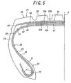
- FIG. 5 is a view illustrating the second embodiment of the invention.
- the cushion rubber layer 50 is arranged over a full region ranging from a widthwise one side end portion of the outer reinforcing ply 42b to the other side end portion thereof through the equator S of the tire. In this way, it is enough to supply one rubber sheet onto a building drum in the building of the tire 21, so that the building operation of the tire 21 becomes easy.
- FIG. 6 is a view illustrating the third embodiment of the invention.
- the widest-width belt ply is not the inner belt ply 35a adjacent and close to the belt reinforcing layer 41, but is an outer belt ply 35b when at least one belt ply (inner belt ply 35a) is arranged with the belt reinforcing layer 41.
- the rubber gauge between the each widthwise outer end portion of the widest-width reinforcing ply 42a, 42b and the portion of the widest-width belt ply (outer belt ply 35b) overlapped therewith can be easily thickened.
- a test example will be described below.
- a conventional tire in which the widths of all reinforcing plies constituting the belt reinforcing layer are narrower than that of the belt layer as shown in FIG. 1, a tire of Example 1 in which only the width of the inner belt ply is wider than that of the belt reinforcing layer and the cushion rubber layer is not arranged therebetween, a tire of Example 2 in which only the width of the inner belt ply is wider than that of the belt reinforcing layer and the cushion rubber layer is arranged therebetween as shown in FIG.
- Example 6 a tire of Example 7 in which the width of the belt reinforcing layer, width of the widest-width belt ply and outer end position of the cushion rubber layer are different from those of the tire of Example 4, tires of Examples 8, 9, 10 in which only the width of the other belt ply (outer belt ply) having a width narrower than that of the widest-width belt ply is different from that of the tire of Example 2, tires of Examples 11, 12, 13 in which only the hardness of the cushion rubber layer is different from that of the tire of Example 2, a tire of Example 14 in which only the hardness of the lateral rubber layer is different from that of the tire of Example 2, tires of Examples 15, 16, 17 in which only the gauge of the cushion rubber layer is different from that of the tire of Example 4, and tires of Examples 18, 19, 20, 21 in which only the inclination angle of the reinforcing element embedded in the belt ply with respect to the equator of the tire is different from that of the tire of Example 2.
- each of these tires has a tire size of 285/60R22.5, a tire width W of 290 mm, a coating rubber gauge for the reinforcing ply of 0.35 mm, a coating rubber gauge for the belt ply of 0.30 mm, a total gauge T of these coating rubbers of 0.65 mm, a JIS hardness of the coating rubber for the reinforcing ply of 70, and a JIS hardness of the coating rubber for the belt ply of 76.
- the width Wp is a width of the widest-width reinforcing ply (mm)
- the belt ply width is a width of an inner belt ply (mm) at a left side of a slash and a width of an outer belt ply (mm) at a right side of the slash
- the inclination angle a is an inclination angle (degree) of a reinforcing element in the outer belt ply with respect to the equatorial plane of the tire at a left side of a slash and an inclination angle (degree) of a reinforcing element in the inner belt ply with respect to the equatorial plane at a right side of the slash
- the gauge E is a gauge of the cushion rubber layer (mm)
- the gauge ratio G/T is a value of dividing the rubber gauge G between ply cords between the each widthwise outer end portion of the widest-width
- each of the above tires is mounted onto a rim having a size of 9.00 ⁇ 22.5 and inflated under an internal pressure of 900 KPa and thereafter run on a drum at a speed of 60 km while applying a load of 40.0 kN until troubles such as separation failure and the like are caused.
- the results are shown in a column of "running index" of Tables 1 and 2 on the basis that the conventional tire is 100. In this case, the index of 100 is 17,500 km.
- a displacement quantity between the belt layer and the belt reinforcing layer at a position separated from the ground contact region of each tire by 60 degrees in the circumferential direction is determined by simulation and the result is shown by an index on the basis that Example 20 in which the inclination angle of the reinforcing element in the belt ply with respect to the tire equator is 40 degrees is 100.
- the belt durability can be improved by effectively suppressing the interlayer separation between the each widthwise outer end portion of the belt reinforcing layer and the belt layer.
Landscapes
- Engineering & Computer Science (AREA)
- Mechanical Engineering (AREA)
- Tires In General (AREA)
Abstract
Description
| Conventional tire | Tires of Examples | |||||
| 1 | 2 | 3 | 4 | 5 | ||
| Width Wp | 190 | same as in the left | same as in the left | same as in the left | same as in the left | same as in the left |
| Belt ply width | 240/220 | 240/120 | same as in the left | same as in the left | 120/240 | same as in the left |
| Inclination angle A | 22/22 | 52/52 | same as in the left | same as in the left | same as in the left | same as in the left |
| Gauge E | - | - | 1.2 | same as in the left | 2.5 | 4.5 |
| Gauge ratio G/T | 1 | same as in the left | 2.85 | same as in the left | 4.85 | 7.92 |
| Hardness H | - | - | 70 | same as in the left | same as in the left | same as in the left |
| Distance L | - | - | 60 | 0 | 60 | same as in the left |
| Distance M | - | - | 110 | same as in the left | same as in the left | same as in the left |
| Hardness J | 76 | same as in the left | same as in the left | same as in the left | same as in the left | same as in the left |
| Running index | 100 | 118 | 135 | 135 | 142 | 147 |
| Displacement index | - | 92 | 92 | 93 | 92 | 94 |
| Trouble place | end of belt reinforcing in layer | same as in the left | same as in the left | same as in the left | same as in the left | same as in the left |
| Tire of Examples | ||||||
| 6 | 7 | 8 | 9 | 10 | 11 | |
| Width Wp | 190 | 210 | 190 | same as in the left | same as in the left | same as in the left |
| Belt ply width | 120/240 | 120/250 | 240/150 | 240/160 | 240/170 | 240/120 |
| Inclination angle A | 52/52 | same as in the left | same as in the left | same as in the left | same as in the left | same as in the left |
| Gauge E | 2.5 | same as in the left | 1.2 | same as in the left | same as in the left | same as in the left |
| Gauge ratio G/T | 4.85 | same as in the left | 2.85 | same as in the left | same as in the left | same as in the left |
| Hardness H | 57 | 70 | same as as in the left | same as as in the left | same as in the left | 52 |
| Distance L | 60 | same as in the left | same as in the left | same as in the left | same as in the left | same as in the left |
| Distance M | 110 | 115 | 110 | same as in the left | same as in the left | same as in the left |
| Hardness J | 76 | same as in the left | same as in the left | same as in the left | same as in the left | same as in the left |
| Running index | 153 | 134 | 129 | 116 | 111 | 112 |
| Displacement index | 93 | 92 | 93 | 94 | 98 | 94 |
| Trouble place | end of belt reinforcing layer | same as in the left | same as in the left | same as in the left | same as in the left | separation in cushion rubber layer |

Claims (13)
- A pneumatic radial tire comprising a carcass layer toroidally extending between a pair of bead portions, a belt layer arranged on a radially outer side of the carcass layer and comprised of at least two belt plies embedded with reinforcing elements inclining in opposite directions with respect to an equator of the tire, and a belt reinforcing layer arranged between the carcass layer and the belt layer and comprised of at least one reinforcing ply embedded with reinforcing elements extending substantially in a circumferential direction, provided that a width Wp of a widest-width reinforcing ply among the reinforcing plies is 0.6 times or more a tire width W, in which only a widest-width belt ply among the belt plies is arranged so as to locate each widthwise outer end thereof outward from each widthwise outer end of the widest-width reinforcing ply in the widthwise direction.
- A pneumatic radial tire according to claim 1, wherein an inclination angle of the reinforcing element embedded in the belt ply with respect to the equator of the tire is within a range of 40-60 degrees in all belt plies.
- A pneumatic radial tire according to claim 1 or 2, wherein a width Wn of the remaining belt ply(s) having a width narrower than that of the widest-width belt ply is within a range of 0.2-0.8 times a width Wp of the widest-width belt reinforcing ply.
- A pneumatic radial tire according to any one of claims 1 to 3, wherein a cushion rubber layer is interposed at least between the each widthwise outer end portion of the widest-width reinforcing ply and a portion of the belt ply overlapped therewith.
- A pneumatic radial tire according to claim 4, wherein when a total gauge of coating rubbers mutually opposed to each other in the mutually adjoining reinforcing ply and belt ply is T, a rubber gauge G including the total gauge T between the each widthwise outer end portion of the widest-width reinforcing ply and the portion of the belt ply overlapped therewith including the cushion rubber layer interposed therebetween is rendered into a range of 2-10 times the total gauge T.
- A pneumatic radial tire according to claim 4 or 5, wherein the cushion rubber layer is made of rubber having a JIS hardness equal to or less than the JIS hardness of the coating rubber for the belt ply.
- A pneumatic radial tire according to claim 6, wherein the cushion rubber layer is made of rubber having a JIS hardness of 55-80.
- A pneumatic radial tire according to any one of claims 4 to 7, wherein the widthwise outer end of the cushion rubber layer is located inward from the each widthwise outer end of the widest-width belt ply in the widthwise direction.
- A pneumatic radial tire according to any one of claims 1 to 8, wherein a lateral rubber layer made of rubber having a JIS hardness equal to or more than the JIS hardness of the coating rubber for the reinforcing ply is arranged at each widthwise outside of the widest-width reinforcing ply.
- A pneumatic radial tire according to claim 9, wherein the widthwise outer end of the lateral rubber layer is extended outward from the widthwise outer end of the widest-width belt ply in the widthwise direction.
- A pneumatic radial tire according to claim 9 or 10, wherein the lateral rubber layer is made of rubber having a JIS hardness higher than that of the cushion rubber layer.
- A pneumatic radial tire according to any one of claims 1 to 11, wherein the widest-width belt ply is arranged adjacent to the belt reinforcing layer.
- A pneumatic radial tire according to any one of claims 1 to 11, wherein at least one belt ply is arranged between the widest-width belt ply and the belt reinforcing layer.
Applications Claiming Priority (3)
| Application Number | Priority Date | Filing Date | Title |
|---|---|---|---|
| JP2001354119A JP4046502B2 (en) | 2001-11-20 | 2001-11-20 | Pneumatic radial tire |
| JP2001354119 | 2001-11-20 | ||
| PCT/JP2002/011896 WO2003043837A1 (en) | 2001-11-20 | 2002-11-14 | Pneumatic radial tire |
Publications (3)
| Publication Number | Publication Date |
|---|---|
| EP1454766A1 true EP1454766A1 (en) | 2004-09-08 |
| EP1454766A4 EP1454766A4 (en) | 2008-06-18 |
| EP1454766B1 EP1454766B1 (en) | 2010-12-22 |
Family
ID=19166019
Family Applications (1)
| Application Number | Title | Priority Date | Filing Date |
|---|---|---|---|
| EP02780100A Expired - Lifetime EP1454766B1 (en) | 2001-11-20 | 2002-11-14 | Pneumatic radial tire |
Country Status (6)
| Country | Link |
|---|---|
| US (1) | US7306021B2 (en) |
| EP (1) | EP1454766B1 (en) |
| JP (1) | JP4046502B2 (en) |
| CN (2) | CN101306629B (en) |
| DE (1) | DE60238711D1 (en) |
| WO (1) | WO2003043837A1 (en) |
Cited By (4)
| Publication number | Priority date | Publication date | Assignee | Title |
|---|---|---|---|---|
| EP1637354A4 (en) * | 2003-05-21 | 2008-10-01 | Bridgestone Corp | Pneumatic tire |
| EP2113398A4 (en) * | 2007-02-23 | 2010-12-08 | Bridgestone Corp | RADIAL TIRES |
| US10569602B2 (en) | 2013-02-12 | 2020-02-25 | Bridgestone Corporation | Heavy load tire with specified belt layers |
| EP3231634B1 (en) * | 2016-04-13 | 2020-05-27 | Sumitomo Rubber Industries, Ltd. | Pneumatic tire |
Families Citing this family (31)
| Publication number | Priority date | Publication date | Assignee | Title |
|---|---|---|---|---|
| BRPI0412723B1 (en) * | 2003-07-18 | 2013-12-24 | Michelin Rech Tech | RADIAL HOUSING PNEUMATIC |
| JP4526363B2 (en) * | 2004-11-30 | 2010-08-18 | 株式会社ブリヂストン | Pneumatic tire |
| JP4703644B2 (en) * | 2005-03-29 | 2011-06-15 | 株式会社ブリヂストン | Heavy duty pneumatic tire |
| JP4721770B2 (en) * | 2005-05-18 | 2011-07-13 | 株式会社ブリヂストン | Pneumatic tire |
| JP2007112394A (en) * | 2005-10-24 | 2007-05-10 | Bridgestone Corp | Pneumatic tire |
| JP4959182B2 (en) * | 2005-12-12 | 2012-06-20 | 株式会社ブリヂストン | Aircraft radial tire |
| JP4724103B2 (en) * | 2006-12-08 | 2011-07-13 | 株式会社ブリヂストン | Heavy duty pneumatic radial tire |
| JP5087269B2 (en) * | 2006-12-22 | 2012-12-05 | 株式会社ブリヂストン | Pneumatic radial tire |
| JP5060780B2 (en) * | 2006-12-26 | 2012-10-31 | 株式会社ブリヂストン | Pneumatic tire |
| JP5164453B2 (en) * | 2007-07-03 | 2013-03-21 | 株式会社ブリヂストン | Pneumatic tire |
| EP2209610B1 (en) * | 2007-10-31 | 2014-06-04 | Pirelli Tyre S.p.A. | A process for building tyres and tyre obtainable by said process |
| JP5308781B2 (en) * | 2008-11-13 | 2013-10-09 | 株式会社ブリヂストン | Pneumatic tire |
| JP2010155533A (en) * | 2008-12-26 | 2010-07-15 | Bridgestone Corp | Pneumatic tire |
| JP2010137813A (en) * | 2008-12-15 | 2010-06-24 | Bridgestone Corp | Pneumatic tire |
| CN102300724B (en) * | 2008-12-15 | 2014-02-19 | 株式会社普利司通 | Pneumatic tire |
| JP5330820B2 (en) * | 2008-12-16 | 2013-10-30 | 株式会社ブリヂストン | Pneumatic tire |
| JP5345876B2 (en) * | 2009-03-09 | 2013-11-20 | 株式会社ブリヂストン | Pneumatic tire |
| JP2010208505A (en) * | 2009-03-10 | 2010-09-24 | Bridgestone Corp | Tire |
| JP2010208502A (en) * | 2009-03-10 | 2010-09-24 | Bridgestone Corp | Tire |
| JP5290920B2 (en) * | 2009-09-24 | 2013-09-18 | 株式会社ブリヂストン | Pneumatic tire |
| JP5612413B2 (en) * | 2010-09-21 | 2014-10-22 | 株式会社ブリヂストン | Pneumatic tire |
| WO2011036893A1 (en) | 2009-09-24 | 2011-03-31 | 株式会社ブリヂストン | Pneumatic tire |
| CN102343130B (en) * | 2010-07-30 | 2013-08-21 | 林滨 | High-rise building fire fighting robot |
| JP5680988B2 (en) * | 2011-02-25 | 2015-03-04 | 株式会社ブリヂストン | Pneumatic radial tire |
| JP2014169507A (en) | 2013-03-01 | 2014-09-18 | Bridgestone Corp | Steel wire for reinforcing rubber article and rubber article including the same |
| CN105682939B (en) * | 2013-10-29 | 2018-10-19 | 株式会社普利司通 | tire |
| JP5944881B2 (en) * | 2013-11-27 | 2016-07-05 | 株式会社ブリヂストン | tire |
| JP6452337B2 (en) * | 2014-07-23 | 2019-01-16 | 株式会社ブリヂストン | tire |
| JP6358004B2 (en) * | 2014-09-17 | 2018-07-18 | 横浜ゴム株式会社 | tire |
| JP6612594B2 (en) * | 2015-11-17 | 2019-11-27 | Toyo Tire株式会社 | Pneumatic tire |
| US20240424838A1 (en) * | 2023-03-15 | 2024-12-26 | The Goodyear Tire & Rubber Company | Durable tires and related methods |
Family Cites Families (22)
| Publication number | Priority date | Publication date | Assignee | Title |
|---|---|---|---|---|
| CA1214096A (en) * | 1982-10-18 | 1986-11-18 | The Goodyear Tire & Rubber Company | Radial tires and a belt structure therefor |
| BR8305477A (en) * | 1982-10-18 | 1984-07-10 | Goodyear Tire & Rubber | STRUCTURE OF ANNULAR BELT FOR RADIAL TIRE |
| JP2509818B2 (en) | 1987-11-06 | 1996-06-26 | 株式会社ブリヂストン | Flat radial tire |
| US4934429A (en) * | 1987-11-06 | 1990-06-19 | Bridgestone Corporation | Low-section pneumatic radial tires |
| JPH01122705A (en) | 1987-11-06 | 1989-05-16 | Bridgestone Corp | Flat radial tire |
| US5054532A (en) * | 1989-02-06 | 1991-10-08 | Bridgestone Corporation | Pneumatic tires with wavy or zigzag cord ply between belt and carcass |
| JP2783826B2 (en) | 1989-02-06 | 1998-08-06 | 株式会社ブリヂストン | Pneumatic tire |
| JP2783833B2 (en) | 1989-03-09 | 1998-08-06 | 株式会社ブリヂストン | Pneumatic tire |
| EP0414892B1 (en) * | 1989-03-08 | 1993-09-01 | Bridgestone Corporation | Pneumatic radial tire |
| US5051532A (en) * | 1989-12-15 | 1991-09-24 | W. R. Grace & Co.-Conn. | N,N-bis-phosphonomethyl taurine N-oxide and water-soluble salts thereof |
| JP3016622B2 (en) * | 1991-04-27 | 2000-03-06 | 株式会社ブリヂストン | Pneumatic radial tire |
| EP0775725B1 (en) | 1994-08-08 | 2001-05-02 | Asahi Kasei Kabushiki Kaisha | Hydrogenated rubber composition |
| DE19528008A1 (en) * | 1995-07-31 | 1997-02-06 | Sp Reifenwerke Gmbh | Pneumatic vehicle tires |
| FR2740733A1 (en) * | 1995-11-08 | 1997-05-09 | Michelin & Cie | RADIAL "HEAVY-DUTY" TIRE WITH SUMMIT FRAME HAVING A MULTI-PARTITE TABLECLOTH |
| JP3679213B2 (en) * | 1996-01-22 | 2005-08-03 | 株式会社ブリヂストン | Heavy duty pneumatic radial tire |
| DE19802492C1 (en) | 1998-01-23 | 1999-04-15 | Mc Micro Compact Car Ag | Heater-Cooler for motor vehicle |
| ES2221311T3 (en) * | 1998-03-12 | 2004-12-16 | Bridgestone Corporation | ROBUST RADIAL PNEUMATIC COVER. |
| FR2778367B1 (en) * | 1998-05-11 | 2000-06-16 | Michelin & Cie | TIRE WITH TRIANGULAR TOP FRAME |
| JP4523722B2 (en) * | 1999-02-19 | 2010-08-11 | ソシエテ ド テクノロジー ミシュラン | Motorcycle tire having a crown reinforcement with a ply comprising circumferential elements |
| JP2000264014A (en) * | 1999-03-18 | 2000-09-26 | Bridgestone Corp | Radial tire for heavy load |
| JP2001121916A (en) * | 1999-10-27 | 2001-05-08 | Bridgestone Corp | Pneumatic tire |
| JP2001213116A (en) * | 2000-02-07 | 2001-08-07 | Bridgestone Corp | Pneumatic tire |
-
2001
- 2001-11-20 JP JP2001354119A patent/JP4046502B2/en not_active Expired - Lifetime
-
2002
- 2002-11-14 CN CN2008101106582A patent/CN101306629B/en not_active Expired - Fee Related
- 2002-11-14 EP EP02780100A patent/EP1454766B1/en not_active Expired - Lifetime
- 2002-11-14 DE DE60238711T patent/DE60238711D1/en not_active Expired - Lifetime
- 2002-11-14 US US10/496,138 patent/US7306021B2/en not_active Expired - Lifetime
- 2002-11-14 CN CNA028252101A patent/CN1604858A/en active Pending
- 2002-11-14 WO PCT/JP2002/011896 patent/WO2003043837A1/en not_active Ceased
Cited By (7)
| Publication number | Priority date | Publication date | Assignee | Title |
|---|---|---|---|---|
| EP1637354A4 (en) * | 2003-05-21 | 2008-10-01 | Bridgestone Corp | Pneumatic tire |
| US7441576B2 (en) | 2003-05-21 | 2008-10-28 | Bridgestone Corporation | Pneumatic tire |
| EP2113398A4 (en) * | 2007-02-23 | 2010-12-08 | Bridgestone Corp | RADIAL TIRES |
| CN101646571B (en) * | 2007-02-23 | 2011-05-11 | 株式会社普利司通 | Pneumatic radial tire |
| US9499010B2 (en) | 2007-02-23 | 2016-11-22 | Bridgestone Corporation | Pneumatic radial tire |
| US10569602B2 (en) | 2013-02-12 | 2020-02-25 | Bridgestone Corporation | Heavy load tire with specified belt layers |
| EP3231634B1 (en) * | 2016-04-13 | 2020-05-27 | Sumitomo Rubber Industries, Ltd. | Pneumatic tire |
Also Published As
| Publication number | Publication date |
|---|---|
| EP1454766A4 (en) | 2008-06-18 |
| CN1604858A (en) | 2005-04-06 |
| US20050000617A1 (en) | 2005-01-06 |
| WO2003043837A1 (en) | 2003-05-30 |
| US7306021B2 (en) | 2007-12-11 |
| CN101306629A (en) | 2008-11-19 |
| DE60238711D1 (en) | 2011-02-03 |
| JP4046502B2 (en) | 2008-02-13 |
| CN101306629B (en) | 2010-06-02 |
| EP1454766B1 (en) | 2010-12-22 |
| JP2003154808A (en) | 2003-05-27 |
Similar Documents
| Publication | Publication Date | Title |
|---|---|---|
| US7306021B2 (en) | Pneumatic radial tire with belt reinforcing layer between carcass layer and belt layer | |
| JP3645277B2 (en) | Pneumatic tire | |
| EP0949091B1 (en) | Pneumatic tyre | |
| EP0985556A2 (en) | Tubeless tyre | |
| JPH0133362B2 (en) | ||
| EP0346106A1 (en) | Pneumatic tyre | |
| US7188655B2 (en) | Pneumatic tire | |
| CN110167766A (en) | Pneumatic tire for two-wheeled vehicle | |
| CN112996675A (en) | Run flat tire | |
| US20100108226A1 (en) | Pneumatic tire | |
| EP0980770B1 (en) | Pneumatic radial tires | |
| JP4523704B2 (en) | Pneumatic tire | |
| CN108367637A (en) | Pneumatic tire | |
| US6786261B2 (en) | Pneumatic tires | |
| EP1502771A1 (en) | Pneumatic tire, having improved bead portion durability | |
| US6145560A (en) | Heavy duty pneumatic radial tires with specified belt cushion rubbers | |
| JP4353788B2 (en) | Pneumatic tire | |
| US7520307B2 (en) | Pneumatic radial tire | |
| JP4606184B2 (en) | Pneumatic tire | |
| CN116867653A (en) | tire | |
| JPS592908A (en) | Pneumatic tyre | |
| JP3636237B2 (en) | Pneumatic radial tire | |
| JPH0924711A (en) | Pneumatic radial tire | |
| JP4285594B2 (en) | Heavy duty pneumatic tire | |
| JP2006199220A (en) | Pneumatic tire |
Legal Events
| Date | Code | Title | Description |
|---|---|---|---|
| PUAI | Public reference made under article 153(3) epc to a published international application that has entered the european phase |
Free format text: ORIGINAL CODE: 0009012 |
|
| 17P | Request for examination filed |
Effective date: 20040521 |
|
| AK | Designated contracting states |
Kind code of ref document: A1 Designated state(s): AT BE BG CH CY CZ DE DK EE ES FI FR GB GR IE IT LI LU MC NL PT SE SK TR |
|
| AX | Request for extension of the european patent |
Extension state: AL LT LV MK RO SI |
|
| A4 | Supplementary search report drawn up and despatched |
Effective date: 20080520 |
|
| 17Q | First examination report despatched |
Effective date: 20090303 |
|
| GRAP | Despatch of communication of intention to grant a patent |
Free format text: ORIGINAL CODE: EPIDOSNIGR1 |
|
| GRAS | Grant fee paid |
Free format text: ORIGINAL CODE: EPIDOSNIGR3 |
|
| GRAA | (expected) grant |
Free format text: ORIGINAL CODE: 0009210 |
|
| AK | Designated contracting states |
Kind code of ref document: B1 Designated state(s): DE ES FR GB IT |
|
| REG | Reference to a national code |
Ref country code: GB Ref legal event code: FG4D |
|
| REF | Corresponds to: |
Ref document number: 60238711 Country of ref document: DE Date of ref document: 20110203 Kind code of ref document: P |
|
| REG | Reference to a national code |
Ref country code: DE Ref legal event code: R096 Ref document number: 60238711 Country of ref document: DE Effective date: 20110203 |
|
| PG25 | Lapsed in a contracting state [announced via postgrant information from national office to epo] |
Ref country code: ES Free format text: LAPSE BECAUSE OF FAILURE TO SUBMIT A TRANSLATION OF THE DESCRIPTION OR TO PAY THE FEE WITHIN THE PRESCRIBED TIME-LIMIT Effective date: 20110402 |
|
| PLBE | No opposition filed within time limit |
Free format text: ORIGINAL CODE: 0009261 |
|
| STAA | Information on the status of an ep patent application or granted ep patent |
Free format text: STATUS: NO OPPOSITION FILED WITHIN TIME LIMIT |
|
| 26N | No opposition filed |
Effective date: 20110923 |
|
| REG | Reference to a national code |
Ref country code: DE Ref legal event code: R097 Ref document number: 60238711 Country of ref document: DE Effective date: 20110923 |
|
| GBPC | Gb: european patent ceased through non-payment of renewal fee |
Effective date: 20111114 |
|
| PG25 | Lapsed in a contracting state [announced via postgrant information from national office to epo] |
Ref country code: GB Free format text: LAPSE BECAUSE OF NON-PAYMENT OF DUE FEES Effective date: 20111114 |
|
| REG | Reference to a national code |
Ref country code: DE Ref legal event code: R082 Ref document number: 60238711 Country of ref document: DE Representative=s name: MARKS & CLERK (LUXEMBOURG) LLP, LU |
|
| REG | Reference to a national code |
Ref country code: FR Ref legal event code: CA Effective date: 20140812 |
|
| REG | Reference to a national code |
Ref country code: DE Ref legal event code: R081 Ref document number: 60238711 Country of ref document: DE Owner name: BRIDGESTONE CORPORATION, JP Free format text: FORMER OWNER: BRIDGESTONE CORP., TOKIO/TOKYO, JP Effective date: 20140828 Ref country code: DE Ref legal event code: R082 Ref document number: 60238711 Country of ref document: DE Representative=s name: MARKS & CLERK (LUXEMBOURG) LLP, LU Effective date: 20140828 |
|
| REG | Reference to a national code |
Ref country code: FR Ref legal event code: PLFP Year of fee payment: 14 |
|
| REG | Reference to a national code |
Ref country code: FR Ref legal event code: PLFP Year of fee payment: 15 |
|
| PGFP | Annual fee paid to national office [announced via postgrant information from national office to epo] |
Ref country code: IT Payment date: 20161123 Year of fee payment: 15 |
|
| REG | Reference to a national code |
Ref country code: FR Ref legal event code: PLFP Year of fee payment: 16 |
|
| PG25 | Lapsed in a contracting state [announced via postgrant information from national office to epo] |
Ref country code: IT Free format text: LAPSE BECAUSE OF NON-PAYMENT OF DUE FEES Effective date: 20171114 |
|
| PGFP | Annual fee paid to national office [announced via postgrant information from national office to epo] |
Ref country code: DE Payment date: 20201119 Year of fee payment: 19 Ref country code: FR Payment date: 20201120 Year of fee payment: 19 |
|
| REG | Reference to a national code |
Ref country code: DE Ref legal event code: R119 Ref document number: 60238711 Country of ref document: DE |
|
| PG25 | Lapsed in a contracting state [announced via postgrant information from national office to epo] |
Ref country code: DE Free format text: LAPSE BECAUSE OF NON-PAYMENT OF DUE FEES Effective date: 20220601 |
|
| PG25 | Lapsed in a contracting state [announced via postgrant information from national office to epo] |
Ref country code: FR Free format text: LAPSE BECAUSE OF NON-PAYMENT OF DUE FEES Effective date: 20211130 |