EP1454701A1 - Hybrid laser-arc welding method for welding zinc coated steel - Google Patents
Hybrid laser-arc welding method for welding zinc coated steel Download PDFInfo
- Publication number
- EP1454701A1 EP1454701A1 EP04100837A EP04100837A EP1454701A1 EP 1454701 A1 EP1454701 A1 EP 1454701A1 EP 04100837 A EP04100837 A EP 04100837A EP 04100837 A EP04100837 A EP 04100837A EP 1454701 A1 EP1454701 A1 EP 1454701A1
- Authority
- EP
- European Patent Office
- Prior art keywords
- metal material
- laser
- metal
- sheets
- welding
- Prior art date
- Legal status (The legal status is an assumption and is not a legal conclusion. Google has not performed a legal analysis and makes no representation as to the accuracy of the status listed.)
- Withdrawn
Links
Images
Classifications
-
- B—PERFORMING OPERATIONS; TRANSPORTING
- B65—CONVEYING; PACKING; STORING; HANDLING THIN OR FILAMENTARY MATERIAL
- B65H—HANDLING THIN OR FILAMENTARY MATERIAL, e.g. SHEETS, WEBS, CABLES
- B65H75/00—Storing webs, tapes, or filamentary material, e.g. on reels
- B65H75/02—Cores, formers, supports, or holders for coiled, wound, or folded material, e.g. reels, spindles, bobbins, cop tubes, cans, mandrels or chucks
- B65H75/18—Constructional details
- B65H75/24—Constructional details adjustable in configuration, e.g. expansible
- B65H75/242—Expansible spindles, mandrels or chucks, e.g. for securing or releasing cores, holders or packages
- B65H75/243—Expansible spindles, mandrels or chucks, e.g. for securing or releasing cores, holders or packages actuated by use of a fluid
-
- B—PERFORMING OPERATIONS; TRANSPORTING
- B23—MACHINE TOOLS; METAL-WORKING NOT OTHERWISE PROVIDED FOR
- B23K—SOLDERING OR UNSOLDERING; WELDING; CLADDING OR PLATING BY SOLDERING OR WELDING; CUTTING BY APPLYING HEAT LOCALLY, e.g. FLAME CUTTING; WORKING BY LASER BEAM
- B23K26/00—Working by laser beam, e.g. welding, cutting or boring
- B23K26/0093—Working by laser beam, e.g. welding, cutting or boring combined with mechanical machining or metal-working covered by other subclasses than B23K
-
- B—PERFORMING OPERATIONS; TRANSPORTING
- B23—MACHINE TOOLS; METAL-WORKING NOT OTHERWISE PROVIDED FOR
- B23K—SOLDERING OR UNSOLDERING; WELDING; CLADDING OR PLATING BY SOLDERING OR WELDING; CUTTING BY APPLYING HEAT LOCALLY, e.g. FLAME CUTTING; WORKING BY LASER BEAM
- B23K1/00—Soldering, e.g. brazing, or unsoldering
-
- B—PERFORMING OPERATIONS; TRANSPORTING
- B23—MACHINE TOOLS; METAL-WORKING NOT OTHERWISE PROVIDED FOR
- B23K—SOLDERING OR UNSOLDERING; WELDING; CLADDING OR PLATING BY SOLDERING OR WELDING; CUTTING BY APPLYING HEAT LOCALLY, e.g. FLAME CUTTING; WORKING BY LASER BEAM
- B23K26/00—Working by laser beam, e.g. welding, cutting or boring
- B23K26/20—Bonding
- B23K26/21—Bonding by welding
- B23K26/24—Seam welding
- B23K26/244—Overlap seam welding
-
- B—PERFORMING OPERATIONS; TRANSPORTING
- B23—MACHINE TOOLS; METAL-WORKING NOT OTHERWISE PROVIDED FOR
- B23K—SOLDERING OR UNSOLDERING; WELDING; CLADDING OR PLATING BY SOLDERING OR WELDING; CUTTING BY APPLYING HEAT LOCALLY, e.g. FLAME CUTTING; WORKING BY LASER BEAM
- B23K26/00—Working by laser beam, e.g. welding, cutting or boring
- B23K26/20—Bonding
- B23K26/32—Bonding taking account of the properties of the material involved
-
- B—PERFORMING OPERATIONS; TRANSPORTING
- B23—MACHINE TOOLS; METAL-WORKING NOT OTHERWISE PROVIDED FOR
- B23K—SOLDERING OR UNSOLDERING; WELDING; CLADDING OR PLATING BY SOLDERING OR WELDING; CUTTING BY APPLYING HEAT LOCALLY, e.g. FLAME CUTTING; WORKING BY LASER BEAM
- B23K26/00—Working by laser beam, e.g. welding, cutting or boring
- B23K26/346—Working by laser beam, e.g. welding, cutting or boring in combination with welding or cutting covered by groups B23K5/00 - B23K25/00, e.g. in combination with resistance welding
- B23K26/348—Working by laser beam, e.g. welding, cutting or boring in combination with welding or cutting covered by groups B23K5/00 - B23K25/00, e.g. in combination with resistance welding in combination with arc heating, e.g. tungsten inert gas [TIG], metal inert gas [MIG] or plasma welding
-
- B—PERFORMING OPERATIONS; TRANSPORTING
- B23—MACHINE TOOLS; METAL-WORKING NOT OTHERWISE PROVIDED FOR
- B23K—SOLDERING OR UNSOLDERING; WELDING; CLADDING OR PLATING BY SOLDERING OR WELDING; CUTTING BY APPLYING HEAT LOCALLY, e.g. FLAME CUTTING; WORKING BY LASER BEAM
- B23K9/00—Arc welding or cutting
- B23K9/16—Arc welding or cutting making use of shielding gas
-
- B—PERFORMING OPERATIONS; TRANSPORTING
- B23—MACHINE TOOLS; METAL-WORKING NOT OTHERWISE PROVIDED FOR
- B23K—SOLDERING OR UNSOLDERING; WELDING; CLADDING OR PLATING BY SOLDERING OR WELDING; CUTTING BY APPLYING HEAT LOCALLY, e.g. FLAME CUTTING; WORKING BY LASER BEAM
- B23K9/00—Arc welding or cutting
- B23K9/16—Arc welding or cutting making use of shielding gas
- B23K9/167—Arc welding or cutting making use of shielding gas and of a non-consumable electrode
-
- B—PERFORMING OPERATIONS; TRANSPORTING
- B23—MACHINE TOOLS; METAL-WORKING NOT OTHERWISE PROVIDED FOR
- B23K—SOLDERING OR UNSOLDERING; WELDING; CLADDING OR PLATING BY SOLDERING OR WELDING; CUTTING BY APPLYING HEAT LOCALLY, e.g. FLAME CUTTING; WORKING BY LASER BEAM
- B23K2101/00—Articles made by soldering, welding or cutting
- B23K2101/34—Coated articles ; Surface treated articles
-
- B—PERFORMING OPERATIONS; TRANSPORTING
- B23—MACHINE TOOLS; METAL-WORKING NOT OTHERWISE PROVIDED FOR
- B23K—SOLDERING OR UNSOLDERING; WELDING; CLADDING OR PLATING BY SOLDERING OR WELDING; CUTTING BY APPLYING HEAT LOCALLY, e.g. FLAME CUTTING; WORKING BY LASER BEAM
- B23K2103/00—Materials to be soldered, welded or cut
- B23K2103/08—Non-ferrous metals or alloys
-
- B—PERFORMING OPERATIONS; TRANSPORTING
- B23—MACHINE TOOLS; METAL-WORKING NOT OTHERWISE PROVIDED FOR
- B23K—SOLDERING OR UNSOLDERING; WELDING; CLADDING OR PLATING BY SOLDERING OR WELDING; CUTTING BY APPLYING HEAT LOCALLY, e.g. FLAME CUTTING; WORKING BY LASER BEAM
- B23K2103/00—Materials to be soldered, welded or cut
- B23K2103/50—Inorganic materials other than metals or composite materials
-
- B—PERFORMING OPERATIONS; TRANSPORTING
- B65—CONVEYING; PACKING; STORING; HANDLING THIN OR FILAMENTARY MATERIAL
- B65H—HANDLING THIN OR FILAMENTARY MATERIAL, e.g. SHEETS, WEBS, CABLES
- B65H18/00—Winding webs
- B65H18/02—Supporting web roll
- B65H18/04—Interior-supporting
-
- B—PERFORMING OPERATIONS; TRANSPORTING
- B65—CONVEYING; PACKING; STORING; HANDLING THIN OR FILAMENTARY MATERIAL
- B65H—HANDLING THIN OR FILAMENTARY MATERIAL, e.g. SHEETS, WEBS, CABLES
- B65H2301/00—Handling processes for sheets or webs
- B65H2301/40—Type of handling process
- B65H2301/41—Winding, unwinding
- B65H2301/413—Supporting web roll
- B65H2301/4136—Mounting arrangements not otherwise provided for
Definitions
- the present invention relates to a method for a hybrid laser welding multiple sheets of steel together. More particularly, the present invention relates to a method for performing a laser beam welding operation for joining steel stampings to hydro formed parts using a single penetrating lap joint design.
- laser beam machines are known to be employed, not only for cutting flat or otherwise drawn sheet metal along given cutting lines, but also for spot or seam welding sheets together.
- the sheets may be either steel stampings or hydroformed parts which may or may not be coated with a protective layer, such as zinc, on the surface.
- the energy from the laser beam penetrates through the first piece into the second piece of steel, heating portions of the two pieces to a sufficiently high temperature so that they melt and coalesce together to form a lap joint.
- a protective layer such as zinc
- the protective layer vaporizes into a gaseous state and developes pressure between the upper and lower portions of the weld joint.
- the vapor pressure expands out through the molten base metal created by the laser beam and results in weld porosity, excessive spatter and poor weld surface conditions such as undercut, underfill and voids. These conditions can cause failures in the weld at a later point in time.
- two steel sheets for laser welding are held together contacting each other as tightly as possible along the entire weld area by means of grips, so as to ensure, among other things, maximum thermal conduction between the sheets.
- the sheets are then subjected to a laser beam, which welds the sheets together by smelting the metal in the weld area swept by the beam.
- low-vaporizing-temperature material is intended to mean material, such as zinc, that has a melting and vaporizing temperature considerably below that of iron or ferrous.
- Additional methods are known to eliminate these imperfections during the welding process when welding two sheets of metal, the metal being of the type having associated gases tending to be trapped and expand in the weld zone, e.g., vaporized zinc, during welding due to heat from the laser.
- One method adds to the standard laser beam a surrounding stream of pressurized shield gas effective to create a pressure at the surface of the weld zone sufficient to force the molten metal of the two sheets together and force the expanded associated gases out of the weld zone in a direction away from the laser beam, whereby a non-porous weld may be created.
- Another method for welding galvanized material discloses a low vapor pressure mild steel core and a high vapor pressure rich zinc coating including the steps of arranging components of such galvanized material in juxtaposed relationship at a lapped joint and applying a high density laser energy beam along the lapped joint as a weave pattern.
- the weave pattern has a width great enough to bridge the lapped joint and a weave pattern frequency, which forms a predetermined weld pool between the components.
- the lapped joint and weave pattern combine to define a vapor pressure relief path so that the weld pool will not be disrupted during the application of the high density laser energy beam to the galvanized components.
- two sheet metal parts are placed in proximity of each other, wherein one sheet is placed on top of the other piece so that a top surface of the first sheet faces away from the other sheet metal.
- a laser beam is applied to the top surface facing away surface of the second sheet and a feed wire comprising a supplemental metal and a reactive agent is provided at the intersection of the laser beam and the surface to which the laser beam is applied.
- the reactive agent reacts with the zinc in the protective layer steel to prevent at least a portion of the zinc from vaporizing and the supplemental wire acts as filler for a resulting weld to the extent necessary.
- a relative movement is affected between the sheet metal parts and the laser beam to provide a quality laser weld of the two sheet metal parts.
- a pulsed laser beam when laser welding steel sheets that have a thin corrosion protective coating of zinc to melt the material of the sheets and create a weld.
- the laser beam is pulsed ON and OFF and the sheets and pulsed laser beam are moved vertically relative to each other such that laser heating of the material creates a cavity.
- liquid or molten material flows vertically downwardly by gravity to elongate the cavity and thereby facilitate the escape of zinc vapors from the cavity.
- the present invention is directed to a method that provides a single side method for joining steel stampings to hydroformed parts using a penetrating lap design.
- the steel stampings may or may not be coated with a protective layer such as a zinc coating.
- the aforementioned method includes the steps of providing first and second pieces of metallic material in an overlapping relationship, providing a head that includes a laser device and either a GMAW welding or a MIG brazing device in a spaced apart relationship, and moving the head relative to the first and second pieces of metallic material such that the laser cuts completely through the first piece and at least partially into the second piece to form a channel or trough therein that allows a vaporized protective layer to escape.
- the GMAW welding or the MIG brazing material then fills in the excavated channel or trough to weld the two pieces together.
- the laser cuts completely through the first piece of metallic material and partially into the second piece of metallic material to form a keyhole of extended length therein that allows any vaporized protective material to escape and allow GMAW welding or the MIG brazing material to fill in the excavated channel or trough to weld the two pieces together.
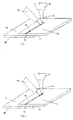
- a first sheet of metal 10 is to be joined with a second sheet of metal 20.
- the first sheet of metal 10 is arranged on top of the second sheet of metal 20.
- Both the first sheet of metal 10 and the second sheet of metal 20 include a protective layer 12, 22 made of a low-vaporizing-temperature material.
- a protective layer 12, 22 made of a low-vaporizing-temperature material.
- a material is zinc.
- Fig. 1 indicates that metal sheet 10 and metal sheet 20 are separate sheets, it should be appreciated that for the purposes of this invention, the two metal sheets may also consist of single sheet bent or wrapped to resemble some form of a U-shape.
- Typical thickness for a protective layer of zinc placed onto a metal sheet ranges from zero to approximately 7.5 microns.
- protective layers 12 and 22 as indicated in Figs. 1 and 2 by no means limits the invention; as is usually the case in actual practice, metal sheets 10 and 20 are each provided with two opposed protective layers (not shown).
- a single protective layer 22 of the second metal sheet 20 is located between sheets 10 and 20 as depicted in Figs. 1 and 2, the ensuing description would obviously in no way be affected if the protective layers 12, 22 of both sheets 10 and 20 were located facing each other between the metal sheets.
- the protective layers 12 and 22 can be located on both a top and a bottom surface of each of the sheets, not depicted in the figures.
- the first metal sheet 10 is positioned on top of the second sheet of metal 20.
- the overlapping portion of the first metal sheet 10 is generally the same shape and/or contour as the corresponding potion of the second sheet of metal 20 over which the first sheet 10 is placed.
- first and second sheets of metal do not align with one another. Such a situation does not limit the applicability of the present invention.
- a gap between the first and second sheets of metal that is relatively slight would not affect the weld achieved through this method. However, the smaller the gap between the two metal sheets, the better formed is the resultant joint weld.
- first sheet of metal 10 and the second sheet of metal 20 have been properly positioned, they are held in place and positioned relative to the head 30 on the welding machine.
- the head 30 of the welding machine is arranged facing the free surface of the first metal sheet 10. While Fig. 1 shows the head 30 oriented to the free face of the first metal sheet 10, it is also possible to orient the head 30 from the underside toward the bottom free surface of second metal sheet 20
- the head 30 of the welding machine is a hybrid version that includes both a laser 34 device coupled with either a gas metal arc welder (hereinafter referred to as "GMAW") 36, in order to join the two metal sheets 10 and 20 in the vicinity of a weld area 40.
- GMAW gas metal arc welder
- the laser 34 is oriented in the head such that the laser 34 precedes the GMAW 36 when making passes to join the two metal sheets 10 and 20.
- the head 30 of the welding machine is positioned facing the top surface of the first metal sheet 10 as described above.
- the laser 34 first contacts the weld area 40 as the head 30 of the welding machine passes over the first and second sheets 10 and 20.
- the laser 34 emits an energy beam sufficient to penetrate through the entire thickness of the first sheet 10 and at least partially into the thickness of the second sheet 20.
- the two pieces of sheet metal 10 and 20 are heated in the vicinity of the weld area 40.
- the heat and/or energy from the laser results in an increase in temperature in the vicinity of the weld area 40 and results with the vaporization of the protective layers 12 and 22 proximate the weld area 40.
- the vaporized gases from the protective layers 12 and 22 then dissipate into the environment.
- the end result once the laser 34 has passed is a channel or trough 42.
- the GMAW 36 fills the channel or trough 42 with a metal inert gas (MIG) brazing material from the GMAW 36 or a conventional welding device mounted on the head 30 so as to follow directly behind the laser 34.
- MIG metal inert gas
- the first and second sheets of metal 10 and 20 are held firmly in place in order to prevent movement.
- the laser 34 cuts a gap 44 completely through both the first and the second sheets of metal 10 and 20.
- the GMAW 36 then follows in trace of the laser 34 and fills the gap 44 will a MIG brazing material in order to form a secure weld in the weld area 42.
- the coating may be of another material other than zinc.
Landscapes
- Engineering & Computer Science (AREA)
- Physics & Mathematics (AREA)
- Optics & Photonics (AREA)
- Mechanical Engineering (AREA)
- Plasma & Fusion (AREA)
- Laser Beam Processing (AREA)
- Arc Welding In General (AREA)
Abstract
Description
Claims (7)
- A method for performing a laser beam welding operation to molecularly bond two pieces of steel together including the steps of:providing at least a first metal material and a second metal material in an overlapping relationship;providing a head that further comprises a laser device and at least one of a GMAW welding and MIG brazing device in a spaced apart relationship;moving said head relative to said first metal material and said second metal material such that said laser;cutting with said laser completely through said first metal material and at least partially into said second metal material to form a channel therein; andfilling said channel with said at least one of a GMAW welding and MIG brazing device to weld said first metal material and said second metal material together.
- The method according to claim 1, further comprising the step of providing a protective layer on at least one of said first metal material and said second metal material.
- The method according to claim 2, wherein said protective layer is a zinc based material.
- The method according to claim 2, further comprising the step of vaporizing said protective layer as said laser cuts said first metal material and said second metal material.
- The method according to claim 4, wherein said vaporized protective layer dissipates into an external environment before the step of filling said channel.
- The method according to claim 1, further comprising the step of moving said head relative to said first metal material and said second metal material such that said laser contacts said first metal material and said second metal material before said at least one of said GMAW welding and said MIG brazing device.
- The method according to claim 1, wherein said second metal material is cut completely therethrough during the step of cutting with said laser.
Applications Claiming Priority (2)
| Application Number | Priority Date | Filing Date | Title |
|---|---|---|---|
| US376624 | 2003-03-03 | ||
| US10/376,624 US6906281B2 (en) | 2003-03-03 | 2003-03-03 | Method for laser welding of metal |
Publications (2)
| Publication Number | Publication Date |
|---|---|
| EP1454701A1 true EP1454701A1 (en) | 2004-09-08 |
| EP1454701A8 EP1454701A8 (en) | 2005-04-27 |
Family
ID=32824732
Family Applications (1)
| Application Number | Title | Priority Date | Filing Date |
|---|---|---|---|
| EP04100837A Withdrawn EP1454701A1 (en) | 2003-03-03 | 2004-03-02 | Hybrid laser-arc welding method for welding zinc coated steel |
Country Status (9)
| Country | Link |
|---|---|
| US (1) | US6906281B2 (en) |
| EP (1) | EP1454701A1 (en) |
| JP (1) | JP2004261870A (en) |
| KR (1) | KR20040078071A (en) |
| CN (1) | CN1532022A (en) |
| AR (1) | AR043463A1 (en) |
| BR (1) | BRPI0400383A (en) |
| CA (1) | CA2459415A1 (en) |
| MX (1) | MXPA04002031A (en) |
Cited By (5)
| Publication number | Priority date | Publication date | Assignee | Title |
|---|---|---|---|---|
| WO2006120222A1 (en) * | 2005-05-11 | 2006-11-16 | Technische Universität Ilmenau | Method and device for the thermal jointing of materials with high-melting oxide coated surfaces |
| CN106808088A (en) * | 2017-03-28 | 2017-06-09 | 广东泰格威机器人科技有限公司 | A kind of seamless welding method of minute surface door of elevator and zinc-plated reinforcing plate |
| GB2569110A (en) * | 2017-11-30 | 2019-06-12 | Acergy France SAS | Arc welding |
| CN112355474A (en) * | 2015-02-09 | 2021-02-12 | 司浦爱激光技术英国有限公司 | Laser welding method using micro-welding piece pattern |
| FR3100729A1 (en) | 2019-09-17 | 2021-03-19 | Psa Automobiles Sa | Process and installation for welding two metal parts |
Families Citing this family (71)
| Publication number | Priority date | Publication date | Assignee | Title |
|---|---|---|---|---|
| DE10309157B4 (en) * | 2003-02-28 | 2011-05-12 | Daimler Ag | Method of laser welding coated panels |
| US20040194275A1 (en) * | 2003-04-02 | 2004-10-07 | Dreistern-Werk Maschinenbau Gmbh & Co. Kg | Method and device for the production of a metal profile |
| AT413667B (en) * | 2004-05-10 | 2006-04-15 | Fronius Int Gmbh | WELDING PROCESS AND LASER HYBRID WELDING BURNER |
| US7253377B2 (en) * | 2005-02-08 | 2007-08-07 | General Motors Corporation | System and method of joining overlapping workpieces |
| US20060261045A1 (en) * | 2005-05-18 | 2006-11-23 | Pei-Chung Wang | Multi-heat source laser brazing system and method |
| US8253062B2 (en) * | 2005-06-10 | 2012-08-28 | Chrysler Group Llc | System and methodology for zero-gap welding |
| KR100751301B1 (en) * | 2005-12-26 | 2007-08-23 | 한국생산기술연구원 | Laser-arc hybrid welding method for galvanized steel sheet and its welding device |
| CN100457363C (en) * | 2006-08-08 | 2009-02-04 | 上海天灵开关厂有限公司 | The technology of laser welding R angle and corner |
| DE102009004798B9 (en) * | 2009-01-13 | 2013-01-31 | Trumpf Laser- Und Systemtechnik Gmbh | Sheet metal component with a laser-welding-compatible triangular corner, associated sheet metal blank and method for producing and optimizing the sheet metal blank |
| US8319148B2 (en) * | 2009-08-20 | 2012-11-27 | General Electric Company | System and method of dual laser beam welding of first and second filler metals |
| DE102010019258B4 (en) * | 2010-05-03 | 2014-12-11 | Thyssenkrupp Steel Europe Ag | Process for the production of tailor-made hot-stamped sheet steel products and sheet steel product |
| KR101205163B1 (en) * | 2010-09-29 | 2012-11-27 | 현대제철 주식회사 | Using heating based alloy and high tensile strength steelplate a tubular beam and trailing arm welding method and a corporate body thereof |
| US9168613B2 (en) | 2010-10-22 | 2015-10-27 | Paul T. Colby | Vertical laser cladding system |
| CN102029476A (en) * | 2011-01-10 | 2011-04-27 | 哈尔滨工业大学 | Method for regulating intermetallic compound for dissimilar material overlap joint through laser-arc double-sided welding |
| US8546720B2 (en) * | 2011-04-13 | 2013-10-01 | General Electric Company | Hybrid welding apparatus and system and method of welding |
| US8766140B2 (en) | 2011-10-06 | 2014-07-01 | Lincoln Global, Inc. | Apparatus and method for laser cleaning of coated materials prior to welding |
| US20130087543A1 (en) * | 2011-10-06 | 2013-04-11 | Lincoln Global, Inc. | Apparatus and method for post weld laser release of gas build up in a gmaw weld |
| KR101272050B1 (en) * | 2011-11-11 | 2013-06-07 | 주식회사 성우하이텍 | Method of laser welding |
| US20130309000A1 (en) * | 2012-05-21 | 2013-11-21 | General Electric Comapny | Hybrid laser arc welding process and apparatus |
| DE102012210012A1 (en) * | 2012-06-14 | 2013-12-19 | Bayerische Motoren Werke Aktiengesellschaft | Method and apparatus for laser remote welding of two coated sheets |
| US8941031B2 (en) * | 2012-08-22 | 2015-01-27 | Caterpillar Inc. | Systems and methods for dual-weave welding |
| CN105008087B (en) | 2012-10-24 | 2018-04-13 | 麦格纳国际公司 | The laser metal deposition cladding of weld seam in automotive component |
| KR101425800B1 (en) * | 2012-11-02 | 2014-08-06 | 주식회사 성우하이텍 | Method of laser welding |
| US10971896B2 (en) | 2013-04-29 | 2021-04-06 | Nuburu, Inc. | Applications, methods and systems for a laser deliver addressable array |
| KR102143220B1 (en) | 2013-04-29 | 2020-08-11 | 마크 에스. 제디커 | Devices, systems, and methods for three-dimensional printing |
| US11612957B2 (en) * | 2016-04-29 | 2023-03-28 | Nuburu, Inc. | Methods and systems for welding copper and other metals using blue lasers |
| US10562132B2 (en) | 2013-04-29 | 2020-02-18 | Nuburu, Inc. | Applications, methods and systems for materials processing with visible raman laser |
| SG10201404701SA (en) | 2013-09-24 | 2015-04-29 | United Technologies Corp | Welded assemblies and methods of making welded assemblies |
| US20160016262A1 (en) * | 2014-07-17 | 2016-01-21 | Midway Products Group, Inc. | Laser welding process |
| US11646549B2 (en) | 2014-08-27 | 2023-05-09 | Nuburu, Inc. | Multi kW class blue laser system |
| GB201502149D0 (en) * | 2015-02-09 | 2015-03-25 | Spi Lasers Uk Ltd | Apparatus and method for laser welding |
| US10688595B2 (en) * | 2015-06-02 | 2020-06-23 | GM Global Technology Operations LLC | Laser welding overlapping metal workpieces |
| WO2017056965A1 (en) * | 2015-09-30 | 2017-04-06 | 三菱電機株式会社 | Welding method and welding device |
| US10512986B2 (en) * | 2016-02-15 | 2019-12-24 | Ford Global Technologies, Llc | Laser welding process |
| CN109219498B (en) * | 2016-03-16 | 2021-10-01 | 通用汽车环球科技运作有限责任公司 | Rapid remote laser welding of stacked metal workpieces |
| CN105643103B (en) * | 2016-03-31 | 2017-11-21 | 长沙理工大学 | Laser lap welding method for galvanized steel sheet |
| US20220072659A1 (en) * | 2016-04-29 | 2022-03-10 | Nuburu, Inc. | Methods and Systems for Reducing Hazardous Byproduct from Welding Metals Using Lasers |
| EP3449537A4 (en) | 2016-04-29 | 2020-07-08 | Nuburu, Inc. | MONOLITHIC FIBER LASER WITH VISIBLE WAVELENGTH |
| KR20210134087A (en) * | 2016-04-29 | 2021-11-08 | 누부루 인크. | Visible laser welding of electronic packaging, automotive electrics, battery and other components |
| US12172377B2 (en) | 2016-04-29 | 2024-12-24 | Nuburu, Inc. | Blue laser metal additive manufacturing system |
| CN109689279A (en) | 2016-04-29 | 2019-04-26 | 努布鲁有限公司 | Visible Light Laser Additive Manufacturing |
| CN109462986B (en) * | 2016-07-14 | 2021-01-26 | 通用汽车环球科技运作有限责任公司 | Multiple laser spot welding of coated steels |
| CN106735770A (en) * | 2016-12-26 | 2017-05-31 | 广州三五汽车部件有限公司 | It is a kind of to prevent galvanized steel plain sheet from welding the device and method for producing oxide-film |
| EP3576899B1 (en) | 2017-01-31 | 2026-04-01 | Nuburu, Inc. | Method for welding copper using blue laser |
| CN110234460B (en) * | 2017-02-24 | 2021-06-29 | Nok株式会社 | Laser welding method |
| DE102017105900A1 (en) * | 2017-03-20 | 2018-09-20 | Kirchhoff Automotive Deutschland Gmbh | Method for end-side laser welding |
| WO2018195510A1 (en) | 2017-04-21 | 2018-10-25 | Nuburu, Inc. | Multi-clad optical fiber |
| WO2018227382A1 (en) * | 2017-06-13 | 2018-12-20 | GM Global Technology Operations LLC | Method for laser welding metal workpieces using a combination of weld paths |
| US10804680B2 (en) | 2017-06-13 | 2020-10-13 | Nuburu, Inc. | Very dense wavelength beam combined laser system |
| CN107876983B (en) * | 2017-12-27 | 2023-05-23 | 长沙理工大学 | A method and system for remote welding of galvanized steel sheets for vehicles |
| EP3520945B1 (en) * | 2018-02-05 | 2021-01-13 | Ningbo Geely Automobile Research & Development Co. Ltd. | Laser brazing process |
| HUE072679T2 (en) * | 2018-03-30 | 2025-12-28 | Furukawa Electric Co Ltd | Welding method and welding apparatus |
| JP7036683B2 (en) * | 2018-07-03 | 2022-03-15 | トヨタ自動車株式会社 | Laser welding method |
| CN109131566B (en) * | 2018-09-11 | 2021-11-02 | 奇瑞汽车股份有限公司 | Overlapping structure of automobile beam and longitudinal beam and welding method of transverse beam and longitudinal beam |
| WO2020107030A1 (en) | 2018-11-23 | 2020-05-28 | Nuburu, Inc | Multi-wavelength visible laser source |
| JP7119960B2 (en) * | 2018-12-03 | 2022-08-17 | 日本軽金属株式会社 | Joining method |
| US11862927B2 (en) | 2019-02-02 | 2024-01-02 | Nuburu, Inc. | High reliability high power high brightness blue laser diode systems and methods of making the same |
| US11583954B2 (en) * | 2019-03-04 | 2023-02-21 | Kabushiki Kaisha Toshiba | Welding method |
| JP7557676B2 (en) * | 2019-04-19 | 2024-09-30 | パナソニックIpマネジメント株式会社 | Joint structure |
| CN110253145A (en) * | 2019-05-17 | 2019-09-20 | 东莞材料基因高等理工研究院 | Welding method of dissimilar metals between low carbon steel and cast iron |
| JP7284014B2 (en) * | 2019-07-10 | 2023-05-30 | 株式会社ダイヘン | Laser-arc hybrid welding equipment |
| US20210031297A1 (en) * | 2019-08-01 | 2021-02-04 | GM Global Technology Operations LLC | System and method for multi-task laser welding |
| CN110576261B (en) * | 2019-08-21 | 2021-06-25 | 中车青岛四方机车车辆股份有限公司 | Laser stitch welding device and welding method thereof |
| WO2021081661A1 (en) * | 2019-10-31 | 2021-05-06 | Her Majesty The Queen In Right Of Canada As Represented By The Minister Of Natural Resources Canada | Hybrid butt-lap joint, and method of production |
| US12304000B2 (en) * | 2019-12-25 | 2025-05-20 | Nippon Light Metal Company, Ltd. | Joining method |
| CN116940432B (en) * | 2021-03-03 | 2025-12-23 | 杰富意钢铁株式会社 | Laser brazing bonding method |
| CN113523626B (en) * | 2021-07-30 | 2022-09-06 | 江苏徐工工程机械研究院有限公司 | Splicing-free welding method |
| WO2023110583A1 (en) * | 2021-12-17 | 2023-06-22 | Trumpf Laser- Und Systemtechnik Gmbh | Method for welding zinc-coated steel sheets using a laser beam |
| CN115026432B (en) * | 2022-06-29 | 2025-02-25 | 内蒙古工业大学 | Laser-assisted MAG high-speed welding process for galvanized sheet |
| CN115255672B (en) * | 2022-08-25 | 2024-11-29 | 穗华激光科技(清远)有限公司 | Dual laser device, embroidery machine, control method, storage medium and electronic equipment |
| CN119839486B (en) * | 2025-02-28 | 2026-03-17 | 广东利元亨智能装备股份有限公司 | Welding fixtures, welding equipment and welding methods |
Citations (3)
| Publication number | Priority date | Publication date | Assignee | Title |
|---|---|---|---|---|
| JP2002103069A (en) * | 2000-09-29 | 2002-04-09 | Nippon Steel Corp | Laser lap welding method for thin steel plate |
| JP2002144063A (en) * | 2000-11-07 | 2002-05-21 | Nkk Corp | Lap welding method of thin steel sheet and welded thin steel sheet |
| JP2002160082A (en) * | 2000-11-27 | 2002-06-04 | Nkk Corp | Lap welding method and welded thin sheet for galvanized steel sheet |
Family Cites Families (17)
| Publication number | Priority date | Publication date | Assignee | Title |
|---|---|---|---|---|
| DE3478906D1 (en) * | 1983-04-20 | 1989-08-17 | British Shipbuilders Eng | Laser-beamwelding |
| US4649426A (en) | 1984-06-12 | 1987-03-10 | The United States Of America As Represented By The United States Department Of Energy | Electronic imaging system and technique |
| US4684779A (en) * | 1986-01-22 | 1987-08-04 | General Motors Corporation | Laser welding metal sheets with associated trapped gases |
| JPS6330193A (en) * | 1986-07-24 | 1988-02-08 | Mitsubishi Heavy Ind Ltd | Laser welding method |
| US4737612A (en) | 1987-02-04 | 1988-04-12 | Westinghouse Electric Corp. | Method of welding |
| US4803334A (en) | 1987-11-16 | 1989-02-07 | Westinghouse Electric Corp. | Method for laser beam welding metal matrix composite components |
| US4835357A (en) | 1988-06-20 | 1989-05-30 | Williams International Corporation | Sheet metal laser welding |
| JPH0679484A (en) | 1992-07-14 | 1994-03-22 | Mitsubishi Electric Corp | Laser welding method |
| US5408065A (en) | 1992-10-09 | 1995-04-18 | General Motors Corporation | Welding apparatus and process |
| US5371337A (en) | 1992-10-09 | 1994-12-06 | General Motors Corporation | Welding process and apparatus |
| JPH06254689A (en) * | 1993-03-05 | 1994-09-13 | Kawasaki Steel Corp | Laser beam welding method for strip metal |
| US5603853A (en) | 1995-02-28 | 1997-02-18 | The Twentyfirst Century Corporation | Method of high energy density radiation beam lap welding |
| US6191379B1 (en) * | 1999-04-05 | 2001-02-20 | General Electric Company | Heat treatment for weld beads |
| US6303891B1 (en) | 1999-10-28 | 2001-10-16 | Robert B. Taylor | Universal shielding gas for GMAW and FCAW welding and process |
| JP2002144064A (en) * | 2000-02-29 | 2002-05-21 | Nkk Corp | Method and apparatus for welding metal members |
| JP3762676B2 (en) * | 2001-09-17 | 2006-04-05 | 本田技研工業株式会社 | Work welding method |
| JP3753656B2 (en) * | 2001-12-27 | 2006-03-08 | 本田技研工業株式会社 | YAG laser and arc combined welding method and apparatus |
-
2003
- 2003-03-03 US US10/376,624 patent/US6906281B2/en not_active Expired - Fee Related
-
2004
- 2004-03-02 JP JP2004057916A patent/JP2004261870A/en active Pending
- 2004-03-02 EP EP04100837A patent/EP1454701A1/en not_active Withdrawn
- 2004-03-02 CA CA002459415A patent/CA2459415A1/en not_active Abandoned
- 2004-03-03 AR ARP040100674A patent/AR043463A1/en not_active Application Discontinuation
- 2004-03-03 CN CNA2004100387190A patent/CN1532022A/en active Pending
- 2004-03-03 MX MXPA04002031A patent/MXPA04002031A/en unknown
- 2004-03-03 BR BR0400383-7A patent/BRPI0400383A/en not_active Application Discontinuation
- 2004-03-03 KR KR1020040014330A patent/KR20040078071A/en not_active Withdrawn
Patent Citations (3)
| Publication number | Priority date | Publication date | Assignee | Title |
|---|---|---|---|---|
| JP2002103069A (en) * | 2000-09-29 | 2002-04-09 | Nippon Steel Corp | Laser lap welding method for thin steel plate |
| JP2002144063A (en) * | 2000-11-07 | 2002-05-21 | Nkk Corp | Lap welding method of thin steel sheet and welded thin steel sheet |
| JP2002160082A (en) * | 2000-11-27 | 2002-06-04 | Nkk Corp | Lap welding method and welded thin sheet for galvanized steel sheet |
Non-Patent Citations (4)
| Title |
|---|
| GRAF T ET AL: "LASER-HYBRID WELDING DRIVES VW IMPROVEMENTS", WELDING JOURNAL, AMERICAN WELDING SOCIETY. MIAMI, US, vol. 82, no. 1, January 2003 (2003-01-01), pages 42 - 48, XP001177395, ISSN: 0043-2296 * |
| PATENT ABSTRACTS OF JAPAN vol. 2002, no. 08 5 August 2002 (2002-08-05) * |
| PATENT ABSTRACTS OF JAPAN vol. 2002, no. 09 4 September 2002 (2002-09-04) * |
| PATENT ABSTRACTS OF JAPAN vol. 2002, no. 10 10 October 2002 (2002-10-10) * |
Cited By (9)
| Publication number | Priority date | Publication date | Assignee | Title |
|---|---|---|---|---|
| WO2006120222A1 (en) * | 2005-05-11 | 2006-11-16 | Technische Universität Ilmenau | Method and device for the thermal jointing of materials with high-melting oxide coated surfaces |
| CN112355474A (en) * | 2015-02-09 | 2021-02-12 | 司浦爱激光技术英国有限公司 | Laser welding method using micro-welding piece pattern |
| CN112355474B (en) * | 2015-02-09 | 2023-04-25 | 通快激光英国有限公司 | Laser welding method using micro weldment pattern |
| CN106808088A (en) * | 2017-03-28 | 2017-06-09 | 广东泰格威机器人科技有限公司 | A kind of seamless welding method of minute surface door of elevator and zinc-plated reinforcing plate |
| CN106808088B (en) * | 2017-03-28 | 2019-01-08 | 广东泰格威机器人科技有限公司 | A kind of seamless welding method of mirror surface door of elevator and zinc-plated stiffening plate |
| GB2569110A (en) * | 2017-11-30 | 2019-06-12 | Acergy France SAS | Arc welding |
| GB2569110B (en) * | 2017-11-30 | 2021-12-15 | Acergy France SAS | Preheating Method and Apparatus for Welding |
| US11213918B2 (en) | 2017-11-30 | 2022-01-04 | Acergy France SAS | Arc welding |
| FR3100729A1 (en) | 2019-09-17 | 2021-03-19 | Psa Automobiles Sa | Process and installation for welding two metal parts |
Also Published As
| Publication number | Publication date |
|---|---|
| US20040173587A1 (en) | 2004-09-09 |
| EP1454701A8 (en) | 2005-04-27 |
| KR20040078071A (en) | 2004-09-08 |
| CN1532022A (en) | 2004-09-29 |
| CA2459415A1 (en) | 2004-09-03 |
| MXPA04002031A (en) | 2005-06-20 |
| JP2004261870A (en) | 2004-09-24 |
| AR043463A1 (en) | 2005-07-27 |
| US6906281B2 (en) | 2005-06-14 |
| BRPI0400383A (en) | 2005-01-04 |
Similar Documents
| Publication | Publication Date | Title |
|---|---|---|
| US6906281B2 (en) | Method for laser welding of metal | |
| US6646225B1 (en) | Method of joining galvanized steel parts using lasers | |
| US6914213B2 (en) | Method and device for overlapping welding of two coated metal sheets with a beam of high energy density | |
| Ono et al. | Development of laser-arc hybrid welding | |
| US4642446A (en) | Laser welding of galvanized steel | |
| EP1534460B2 (en) | Laser welding with beam oscillation | |
| JP5267320B2 (en) | Steel plate lap welding method and steel plate lap weld joint | |
| US8410400B2 (en) | Welded metal laminate structure and method for welding a metal laminate structure | |
| EP0126547B1 (en) | Laser beamwelding | |
| US20020142184A1 (en) | Alloy based laser welding | |
| US6794603B1 (en) | Laser joint welding metal material | |
| EP0503703A2 (en) | Laser-welding of galvanized steel | |
| KR102900441B1 (en) | Laser brazing joining method | |
| US20080035615A1 (en) | Lap welding of steel articles having a corrosion resisting metallic coating | |
| JP4326492B2 (en) | Dissimilar materials joining method using laser welding | |
| JP2007075872A (en) | Laser brazing joining method | |
| Woohyun et al. | Brazability of Aluminum Alloy to Steels using Aluminum Filler Metal- Dissimilar Laser Brazing of Aluminum Alloy and Steels(Report 1)- | |
| CA2371813C (en) | Method of joining metal strip ends together using a consumable insert | |
| JP4978121B2 (en) | Butt joining method of metal plates | |
| JP4931506B2 (en) | Dissimilar material joining method | |
| US20060065639A1 (en) | Method of welding galvanized steel components | |
| JPS6310233Y2 (en) | ||
| JP2001087878A (en) | Laser welding method for micro lapping of sheet material | |
| AU2001251337A1 (en) | Alloy based laser welding | |
| JP2004181476A (en) | Laser welding method of aluminum plated steel sheet and welded part structure |
Legal Events
| Date | Code | Title | Description |
|---|---|---|---|
| PUAI | Public reference made under article 153(3) epc to a published international application that has entered the european phase |
Free format text: ORIGINAL CODE: 0009012 |
|
| AK | Designated contracting states |
Kind code of ref document: A1 Designated state(s): AT BE BG CH CY CZ DE DK EE ES FI FR GB GR HU IE IT LI LU MC NL PL PT RO SE SI SK TR |
|
| AX | Request for extension of the european patent |
Extension state: AL LT LV MK |
|
| 17P | Request for examination filed |
Effective date: 20050307 |
|
| AKX | Designation fees paid |
Designated state(s): AT BE BG CH CY CZ DE DK EE ES FI FR GB GR HU IE IT LI LU MC NL PL PT RO SE SI SK TR |
|
| GRAP | Despatch of communication of intention to grant a patent |
Free format text: ORIGINAL CODE: EPIDOSNIGR1 |
|
| STAA | Information on the status of an ep patent application or granted ep patent |
Free format text: STATUS: THE APPLICATION IS DEEMED TO BE WITHDRAWN |
|
| 18D | Application deemed to be withdrawn |
Effective date: 20071001 |