EP1454521B2 - Wrapping device for bales and baling press - Google Patents
Wrapping device for bales and baling press Download PDFInfo
- Publication number
- EP1454521B2 EP1454521B2 EP04100826.9A EP04100826A EP1454521B2 EP 1454521 B2 EP1454521 B2 EP 1454521B2 EP 04100826 A EP04100826 A EP 04100826A EP 1454521 B2 EP1454521 B2 EP 1454521B2
- Authority
- EP
- European Patent Office
- Prior art keywords
- bale
- wrapping
- advancing element
- clutch
- driveshaft
- Prior art date
- Legal status (The legal status is an assumption and is not a legal conclusion. Google has not performed a legal analysis and makes no representation as to the accuracy of the status listed.)
- Expired - Lifetime
Links
- 238000004804 winding Methods 0.000 claims description 8
- 230000002093 peripheral effect Effects 0.000 claims description 7
- 230000001105 regulatory effect Effects 0.000 claims description 5
- 230000005540 biological transmission Effects 0.000 claims description 4
- 230000008878 coupling Effects 0.000 description 21
- 238000010168 coupling process Methods 0.000 description 21
- 238000005859 coupling reaction Methods 0.000 description 21
- 238000000034 method Methods 0.000 description 12
- 239000000463 material Substances 0.000 description 8
- 230000007257 malfunction Effects 0.000 description 2
- CVOFKRWYWCSDMA-UHFFFAOYSA-N 2-chloro-n-(2,6-diethylphenyl)-n-(methoxymethyl)acetamide;2,6-dinitro-n,n-dipropyl-4-(trifluoromethyl)aniline Chemical compound CCC1=CC=CC(CC)=C1N(COC)C(=O)CCl.CCCN(CCC)C1=C([N+]([O-])=O)C=C(C(F)(F)F)C=C1[N+]([O-])=O CVOFKRWYWCSDMA-UHFFFAOYSA-N 0.000 description 1
- 244000025254 Cannabis sativa Species 0.000 description 1
- 241000196324 Embryophyta Species 0.000 description 1
- 230000015572 biosynthetic process Effects 0.000 description 1
- 230000001276 controlling effect Effects 0.000 description 1
- 238000012544 monitoring process Methods 0.000 description 1
- 239000000123 paper Substances 0.000 description 1
- 239000010902 straw Substances 0.000 description 1
- 230000003319 supportive effect Effects 0.000 description 1
- 239000004753 textile Substances 0.000 description 1
- 239000002699 waste material Substances 0.000 description 1
Images
Classifications
-
- A—HUMAN NECESSITIES
- A01—AGRICULTURE; FORESTRY; ANIMAL HUSBANDRY; HUNTING; TRAPPING; FISHING
- A01F—PROCESSING OF HARVESTED PRODUCE; HAY OR STRAW PRESSES; DEVICES FOR STORING AGRICULTURAL OR HORTICULTURAL PRODUCE
- A01F15/00—Baling presses for straw, hay or the like
- A01F15/07—Rotobalers, i.e. machines for forming cylindrical bales by winding and pressing
- A01F15/071—Wrapping devices
- A01F15/0715—Wrapping the bale in the press chamber before opening said chamber
-
- A—HUMAN NECESSITIES
- A01—AGRICULTURE; FORESTRY; ANIMAL HUSBANDRY; HUNTING; TRAPPING; FISHING
- A01F—PROCESSING OF HARVESTED PRODUCE; HAY OR STRAW PRESSES; DEVICES FOR STORING AGRICULTURAL OR HORTICULTURAL PRODUCE
- A01F15/00—Baling presses for straw, hay or the like
- A01F15/08—Details
- A01F15/0841—Drives for balers
- A01F15/085—Drives for balers for round balers
-
- A—HUMAN NECESSITIES
- A01—AGRICULTURE; FORESTRY; ANIMAL HUSBANDRY; HUNTING; TRAPPING; FISHING
- A01F—PROCESSING OF HARVESTED PRODUCE; HAY OR STRAW PRESSES; DEVICES FOR STORING AGRICULTURAL OR HORTICULTURAL PRODUCE
- A01F15/00—Baling presses for straw, hay or the like
- A01F15/07—Rotobalers, i.e. machines for forming cylindrical bales by winding and pressing
- A01F15/071—Wrapping devices
- A01F2015/0725—Film dispensers for film rollers in a satellite type wrapper, e.g. holding and tensioning means for the film roller
Landscapes
- Life Sciences & Earth Sciences (AREA)
- Environmental Sciences (AREA)
- Storage Of Harvested Produce (AREA)
- Basic Packing Technique (AREA)
Description
Die Erfindung betrifft eine Ballenpresse mit einer Vorrichtung zum Umhüllen eines Ballens mit einer Hüllbahn, mit einem Vortriebselement, vorzugsweise einer Vortriebswalze, welches die Hüllbahn von einem Vorrat, vorzugsweise in der Art einer Rolle, abzieht, und einer Kupplungseinrichtung, über die das Vortriebselement zu Beginn des Wickelvorgangs kurzzeitig angetrieben wird und die während des übrigen Wickelvorgangs eine Mitnahme der Hüllbahn durch den Ballen erlaubt.The invention relates to a baler with a device for wrapping a bale with a wrapping web, with a drive element, preferably a drive roller, which pulls the wrapping web from a supply, preferably in the manner of a roll, and a coupling device, via which the drive element at the beginning the winding process is driven for a short time and allowed during the rest of the winding process entrainment of the wrapping path through the bale.
Die
Die
Die
Derartige Vorrichtungen zum Umhüllen eines Ballens brechen den Umhüllungsvorgang erst dann ab, wenn sich die Hüllbahn bereits um die Vortriebswalze gewickelt hat. Um die Vorrichtung bzw. eine mit einer solchen Vorrichtung versehene Ballenpresse wieder betriebsbereit zu machen, muss die Hüllbahn von der Vortriebswalze entfernt werden, was zeit- und arbeitsaufwändig ist.Such devices for wrapping a bale break off the wrapping process only when the wrapping web has already been wound around the drive roller. In order to make the device or a baler provided with such a device ready for operation, the wrapping web must be removed from the advancing roller, which is time-consuming and labor-intensive.
Aus der
Dieses Problem wird erfindungsgemäß durch die Lehre des Patentanspruchs 1 gelöst, wobei in den weiteren Patentansprüchen Merkmale aufgeführt sind, die die Lösung in vorteilhafter Weise weiterentwickeln.This problem is inventively solved by the teaching of claim 1, wherein in the other claims features are listed, which further develop the solution in an advantageous manner.
Auf diese Weise wird eine Ballenpresse mit einer verbesserten Vorrichtung zum Umhüllen eines Ballens zur Verfügung gestellt, welche verhindert, dass sich die Hüllbahn um die Vortriebswalze bzw. allgemein umIn this way, a baler is provided with an improved apparatus for wrapping a bale, which prevents the wrapping sheet to the driving roller or in general order
Vortriebselement wickelt oder sich aufstaut, wenn sie sich nicht ordnungsgemäß um den Ballen wickelt. Durch das Vorsehen einer Kupplungseinrichtung ist es möglich, dass das Vortriebselement nur zu Beginn des Wickelvorgangs kurzzeitig angetrieben wird, um den Wickelvorgang zu starten. Nachdem ausreichend Hüllbahn bzw. Material von der Rolle bzw. dem Vorrat abgestreift wurde, um in den Bereich des Ballens zu gelangen und durch diesen ergriffen zu werden, wird der Antrieb des Vortriebselements gestoppt. Auf diese Weise wird durch das Vortriebselement kein weiteres Material von dem Vorrat abgezogen. Wurde die Hüllbahn dem Ballen korrekt zugeführt, so wird sie durch diesen ergriffen. Da die Kupplungseinrichtung es erlaubt, dass die Hüllbahn durch den Ballen mitgenommen wird und dieser Vorgang somit nicht durch das Vortriebselement blockiert wird, kann sich der Ballen selbsttätig mit Hüllbahn umwickeln. Wird die Hüllbahn hingegen nicht durch den Ballen ergriffen, so wird sie auch nicht durch das Vortriebselement von dem Vorrat abgezogen.Drive element wraps or accumulates if it does not wrap properly around the bale. By providing a coupling device, it is possible that the driving element is briefly driven only at the beginning of the winding process to start the winding process. After sufficient wrapping material has been stripped from the roll or stock to enter and be gripped by the bale, the propulsion element drive is stopped. In this way, no further material is withdrawn from the supply by the driving element. If the wrapping web has been correctly fed to the bale, it will be gripped by it. Since the coupling device allows the wrapping web to be taken along by the bale and thus this process is not blocked by the driving element, the bale can automatically wrap around with wrapping web. On the other hand, if the wrapping web is not grasped by the bale, then it will not be drawn off from the supply by the driving element.
Verbindet die Kupplungseinrichtung das Vortriebselement selektiv mit seiner Antriebswelle so kann vorgesehen sein, dass diese Antriebswelle, dauerhaft mit einem Antrieb, welcher beispielsweise auch den Ballen in Rotation versetzt, in Verbindung steht. Die Antriebswelle kann beispielsweise über einen Riemenantrieb mit einer angetriebenen Walze verbunden sein, welche auf den Ballen einwirkt.If the coupling device selectively connects the drive element to its drive shaft, provision can be made for this drive shaft to be permanently connected to a drive which, for example, also sets the bale in rotation. The drive shaft may for example be connected via a belt drive with a driven roller, which acts on the bale.
Die Kupplungseinrichtung weist eine Freilaufkupplung auf, so dass sie, insbesondere wenn das Vortriebselement nicht angetrieben wird, eine ungehinderte Bewegung desselben in einer Richtung zulässt und in einer zweiten bzw. entgegengesetzten Richtung eine Drehmomentübertragung ermöglicht.The clutch device has an overrunning clutch, so that, in particular when the drive element is not driven, it permits unimpeded movement thereof in one direction and enables torque transmission in a second or opposite direction.
Die Freilaufkupplung ist zwischen der Antriebswelle und dem Vortriebselement derart angeordnet, dass sich die Antriebswelle in dem Vortriebselement, wenn dieses nicht angetrieben wird bzw. werden soll, in ihrer normalen Drehrichtung frei bewegen kann.The one-way clutch is arranged between the drive shaft and the drive element such that the drive shaft in the drive element, if this is not driven or should be, can move freely in their normal direction of rotation.
In der entgegengesetzten Richtung ist eine Drehmomentübertragung möglich. Dies kann beispielsweise dazu eingesetzt werden, um das durch die von dem Ballen erfasste Hüllbahn angetriebene Vortriebselement abzubremsen, indem seine Drehzahl durch die Freilaufkupplung auf die Drehzahl der Antriebswelle begrenzt wird.In the opposite direction a torque transmission is possible. This can be used, for example, to decelerate the propelling element driven by the wrapping web grasped by the bale by restricting its rotational speed to the rotational speed of the drive shaft by means of the one-way clutch.
Eine derartige Freilaufkupplung ist insbesondere dann günstig, wenn die Antriebswelle dauerhaft angetrieben wird. Dauerhaft ist hierbei so zu verstehen, dass die Antriebswelle zumindest während des Wickelvorgangs angetrieben wird. Bei einer üblichen Anordnung bei der die Antriebswelle mit einer den Ballen in Rotation versetzenden Walze über einen Riementrieb verbunden ist, kann aber auch vorgesehen sein, dass die Antriebswelle während des gesamten Ballenbildungsvorgangs angetrieben wird.Such a one-way clutch is particularly advantageous when the drive shaft is driven permanently. Permanently here is to be understood that the drive shaft is driven at least during the winding process. In a conventional arrangement in which the drive shaft is connected to a roller which sets the bale in rotation via a belt drive, it can also be provided that the drive shaft is driven during the entire bale forming process.
Wird das Vortriebselement mit einer Geschwindigkeit angetrieben, die geringer ist als die Umfangsgeschwindigkeit des Ballens, so kann dadurch ein Dehnen oder Spannen der einenends durch den Ballen ergriffenen Hüllbahn erzielt werden, wodurch diese sich dicht an den Ballen anlegen kann.If the propelling element is driven at a speed which is less than the peripheral speed of the bale, this can be achieved by stretching or tensioning the enveloping web grasped at one end by the bale, whereby it can make contact tightly with the bale.
Der Antrieb des Vortriebselements erfolgt durch Mittel, welche die Antriebswelle drehfest mit dem Vortriebselement verbinden. Diese Mittel sind in der Art einer Kupplung ausgebildet, welche in aktiviertem bzw. eingerücktem Zustand einen Antrieb des Vortriebselements durch die Antriebswelle ermöglicht und bewirkt, dass das Vortriebselements in ausgerücktem Zustand der Kupplung nicht angetrieben wird.The propulsion element is driven by means which connect the drive shaft in a rotationally fixed manner to the propulsion element. These means are designed in the manner of a coupling which, in the activated or engaged state, enables the driving element to be driven by the drive shaft and causes the driving element to not be driven in the disengaged state of the coupling.
Die Kupplungseinrichtung wirkt mit einer Steuer- oder Regeleinrichtung zusammen, die insbesondere die Stellung der Kupplung in Abhängigkeit von dem Fortgang des Ballenbildungs- bzw. Wickelvorgangs bestimmen kann. Eine derartige Steuer- oder Regeleinrichtung ist häufig zur Überwachung und Steuerung bzw. Reglung des Ballenbildungs- bzw. Wickelprozesses vorgesehen, so dass die zusätzliche Funktion in eine bereits vorhandene Einrichtung implementiert werden kann.The coupling device cooperates with a control or regulating device, which in particular can determine the position of the coupling as a function of the progress of the bale forming or winding process. Such a control or regulating device is frequently provided for monitoring and controlling the bale forming or winding process, so that the additional function can be implemented in an already existing device.
Eine Vorrichtung zum Umhüllen eines Ballens kann in der Industrie an Ballenpressen Verwendung finden, welche Ballen aus Papier, Abfällen, textilen Materialien etc. bilden. Besonders geeignet ist eine solche Vorrichtung aber zur Verwendung an einer landwirtschaftlichen Ballenpressen für Ballen aus landwirtschaftlichen Erntegütern, da diese üblicherweise an ein Zugfahrzeug angehängt sind und durch eine Bedienungsperson dieses Zugfahrzeugs überwacht werden müssen. Fehlfunktionen einer Umhüllungseinrichtung sind für diese Bedienungspersonen schwer festzustellen und werden häufig erst bei Auswurf des Ballens bemerkt.An apparatus for wrapping a bale can be used in industry on balers which form bales of paper, waste, textile materials, etc. However, such a device is particularly suitable for use on an agricultural baler for bales of agricultural crops, since these are usually attached to a towing vehicle and must be monitored by an operator of this towing vehicle. Malfunction of a wrapping device are difficult to detect for these operators and are often noticed only when ejecting the bale.
In der Zeichnung ist ein nachfolgend näher beschriebenes Ausführungsbeispiel der Erfindung dargestellt. Es zeigt:
- Fig. 1
- eine Ballenpresse mit einer Vorrichtung zum Umwickelns eines Ballens mit einer Hüllbahn,
- Fig. 2
- die Vorrichtung aus
Fig. 1 in einer genaueren Darstellung, mit einer Kupplungseinrichtung zum selektiven Antrieb eines Vortriebselements und - Fig. 3
- die Kupplungseinrichtung aus
Fig. 2 .
- Fig. 1
- a baler with a device for wrapping a bale with a wrapping web,
- Fig. 2
- the device off
Fig. 1 in a more detailed representation, with a coupling device for selectively driving a propulsion element and - Fig. 3
- the coupling device
Fig. 2 ,
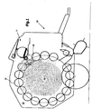
Bei der Ballenpresse 10 kann es sich um eine bekannte Bauart handeln, d.h. mit einem Pressraum 12 konstanter oder variabler Größe, welcher ausschließlich oder in Kombination von Riemen, Ketten, oder wie in dem Ausführungsbeispiel von Walzen 20 umgeben wird.The
Eine derartige Ballenpresse 10 kann in der Landwirtschaft zum Bilden von Ballen 16 aus Erntegut, wie z.B. Stroh, Heu oder Gras eingesetzt werden. Es ist aber auch eine Verwendung in industriellen Bereichen denkbar.Such a
Die Vorrichtung 14 ist in der vorliegenden Ausführungsform an der Vorderseite der Ballenpresse 10 vorgesehen. Die Hüllbahn 18 wird durch einen Spalt zwischen zwei benachbarten Walzen 20 hindurch dem Pressraum 12 zugeführt, wo sie von dem in Drehung versetzten Ballen 16 mitgenommen wird. Die Vorrichtung 14 kann in einem mittleren Bereich der Ballenpresse 10 oder auch vor oder oberhalb des Pressraums 12 angeordnet sein.The device 14 is provided in the present embodiment at the front of the
Mittels der Hüllbahn 18 wird der Ballen 16 gebunden und somit daran gehindert, nach einem Verlassen der Ballenpresse 10 auseinander zu fallen. Bei der Hüllbahn 18 kann es sich um Folie, Netz, Gewebe, Papier oder dergleichen handeln.By means of the wrapping
Es wird nun auch auf
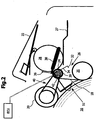
Die Vorrichtung 14 weist ein Gehäuse 22, eine zukünftig als Vortriebselement 24 bezeichnete Vortriebswalze und eine Trenneinrichtung 26 auf. Das Gehäuse 22 enthält einen Fachboden 27, auf welchem die Hüllbahn 18 als Rolle 28 gelagert wird. Der Fachboden 27 kann auch derart ausgebildet sein, dass er mehrere Rollen 28 bevorratet und/oder Stufen oder Mulden zu deren Lagesicherung aufweist.The device 14 has a
Das Vortriebselement 24 ist auf seiner Umfangsfläche mit einem Belag hohen Reibwerts versehen und kann in Drehung versetzt werden. Die Drehung hilft anfänglich, die Hüllbahn 18 von der Rolle 28 abzuziehen. Die Rolle 28 befindet sich oberhalb der Auflageebene des Fachbodens 27 und kommt in ihrer Betriebsstellung mit einem Bereich, der etwa einer 6 bis 9 Uhr Stellung entspricht, an der Vortriebswalze 24 zur Anlage. Durch das Vortriebselement 24 wird die Hüllbahn 18 von der Rolle 28 abgezogen und durch den Spalt zwischen den benachbarten Walzen 20 in den Pressraum 12 geführt. Bei einem ordnungsgemäßen Betrieb wird die Hüllbahn 18 von dem rotierenden Ballen 16 erfasst und hüllt diesen ein.The
Die Trenneinrichtung 26 weist ein Messer 32 auf, welches auf einem Arm 34 um ein Lager 36 schwenkbar befestigt ist, um in den Weg der Hüllbahn 18 einzutreten und diese zu durchtrennen bzw. ein Abreißen zu bewirken, wenn der Einhüllvorgang abgeschlossen ist. Ein Verschwenken des Messers 32 erfolgt über einen Hydraulikmotor 38, welcher mittels einer bekannten Steuer- bzw. Regeleinrichtung (ECU) betätigt wird.The separating
Darüber hinaus ist mit dem Arm 34 ein weiterer Arm 48 schwenkbar verbunden, dessen Stellung ebenfalls von dem Hydraulikmotor 38 bestimmt wird. Im vorliegenden Ausführungsbeispiel ist an dem Arm 38 eine Leiteinrichtung 51 schwenkbar vorgesehen. Eine derartige Leiteinrichtung 51 kann der deutschen Patentanmeldung mit dem Aktenzeichen
Befindet sich der Hydraulikmotor 38 in seiner eingefahrenen Stellung so befindet sich das Messer 32 in einer derart verschwenkten Stellung, dass es den Lauf der Hüllbahn 18 nicht beeinflusst.The
Das Vortriebselement 24 ist durch eine Antriebswelle 39 selektiv antreibbar, die über einen Riementrieb 40 mit einer der Walzen 20 in Verbindung steht, wobei diese Walze 20 von einem nicht dargestellten Antrieb in Rotation versetzt werden kann.The
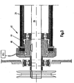
Die selektive Verbindung der Antriebswelle 39 mit dem Vortriebselement 24 erfolgt über eine Kupplungseinrichtung 42, welche zwischen der Antriebswelle 39 und dem Vortriebselement 24 vorgesehen ist.The selective connection of the
Es wird nun auch auf
Darüber hinaus weist die Kupplungseinrichtung 42 eine ansteuerbare Kupplung 46 auf, welche das Vortriebselement 24 mit der Antriebswelle 39 in Abhängigkeit von einem Steuersignal drehfest verbinden kann.In addition, the
Im Folgenden soll auf die Funktionsweise der Vorrichtung 14 genauer eingegangen werden. Hierzu wird sowohl auf
Ist die Bildung des Ballens 16 in dem Pressraum 12 abgeschlossen, was in bekannter Art und Weise durch einen nicht dargestellten Sensor, welcher beispielsweise mechanisch oder optisch die Dicke des Ballens 16 bestimmt, ermittelt wird, wird die Vorrichtung 14 aktiviert. Dies geschieht, indem der Hydraulikmotor 38 von der Steuer- bzw. Regeleinrichtung (ECU) angesteuert, in seine in
Darüber hinaus liefert die Steuer- bzw. Regeleinrichtung (ECU) ein Steuersignal an die Kupplungseinrichtung 42. Aufgrund dieses Steuersignals stellt die Kupplung 46 eine drehfeste Verbindung zwischen der Antriebswelle 39 und dem Vortriebselement 24 her.In addition, the control unit (ECU) supplies a control signal to the
Das nun rotierend angetriebene Vortriebselement 24 zieht die Hüllbahn 18 von der Rolle 28 ab und fördert diese in Richtung des Ballens 18. Die Leiteinrichtung 51 wirkt hierbei unterstützend, indem sie die Hüllbahn 18 an den Ballen 16 heranführt.The
Nach einer kurzen Zeitdauer, welche derart ausgelegt ist, dass durch das Vortriebselement 24 eine derartige Menge an Hüllbahn 18 von der Rolle 28 abgezogen wurde, die ausreicht, um an den Ballen 16 heranzugelangen und durch diesen erfasst zu werden, wird die Kupplung 46 durch die Steuer- bzw. Regeleinrichtung (ECU) derart angesteuert, dass die Kupplung 46 die drehfeste Verbindung zwischen der Antriebswelle 39 und dem Vortriebselement 24 trennt.After a short period of time, which is designed such that by the driving
Ein weiteres Abziehen von Hüllbahn 18 von der Rolle 28 erfolgt nun dadurch, dass die Hüllbahn 18 von dem rotierenden Ballen 16 ergriffen wurde und dieser die Hüllbahn 18 aufgrund seiner Rotation mitführt und um sich wickelt.Another removal of wrapping
Bei der gezeigten Anordnung würde das frei auf der Antriebswelle 39 angeordnete Vortriebselement 24 durch die durch den Ballen 16 abgezogene Hüllbahn 18 mit einer Drehzahl rotieren, die die Drehzahl der Antriebswelle 39 übersteigt. Aufgrund der Freilaufkupplung 44 ist die Drehzahl des Vortriebselements 24 aber auf die Drehzahl der Antriebswelle 39 begrenzt. Die Antriebswelle 39 wiederum ist über den Riementrieb 40 derart mit der angetriebenen Rolle 20 verbunden, dass die Umfangsgeschwindigkeit des Vortriebselements 24 durch die Freilaufkupplung 44 auf eine Umfangsgeschwindigkeit begrenzt wird, welche geringer ist als die Umfangsgeschwindigkeit des Ballens 16. Die Hüllbahn 18 wird durch das Vortriebselement 24 gebremst und somit gedehnt bzw. gespannt. Dies ist wünschenswert, um zu bewirken, dass die Hüllbahn 18 sich dicht an den Ballen 16 anlegt und diesen fest umschließt.In the arrangement shown, the freely disposed on the
Folgt die Hüllbahn 18 nicht dem vorgegebenen Pfad und wird sie somit auch nicht durch den Ballen 16 ergriffen, so erfolgt kein Transport der Hüllbahn 18 durch den Ballen 16. Da das Vortriebselement 24 durch die Antriebswelle 39 über die Kupplung 46 nur zu Beginn des Wickelvorgangs kurzzeitig angetrieben wird, wird die Hüllbahn 18 durch das Vortriebselement 24 nicht weiter von der Rolle 28 abgezogen und es kann nicht zu einem Umwickeln des Vortriebselements 24 durch die Hüllbahn 18 kommen.If the wrapping
Claims (3)
- Baler (10) with a device (14) for wrapping a bale (16) with a wrapping web (18), with an advancing element (24), preferably an advancing roller, which pulls off the wrapping web (18) from a store, preferably in the manner of a reel (28), and with a clutch mechanism (42), wherein the clutch mechanism has an activatable clutch (46), via which the advancing element (24) is briefly driven at the beginning of the winding operation and which permits the wrapping web (18) to be carried along by the bale (16) during the remaining wrapping operation, wherein the brief period of time is configured in such a manner that, by means of the advancing element (24), an amount of wrapping web (18) can be pulled off from the reel (28) to an extent sufficing in order to reach the bale (16) and to be grasped by the latter, characterized in that the clutch mechanism (42) is provided between the drive shaft (39) of the advancing element and the advancing element (24), and a selective connection of the driveshaft (39) to the advancing element (24) takes place via the clutch mechanism (42), wherein a control or regulating mechanism (ECU) supplies a control signal to the clutch mechanism (42), on the basis of which signal a non-rotatable connection between the driveshaft (39) and the advancing element (24) can be produced by the clutch (46), and wherein the clutch (46) can be activated by the control or regulating mechanism (ECU) in such a manner that a non-rotatable connection between the driveshaft (39) and the advancing element (24) can be separated by the clutch (46), and that the clutch mechanism (42) has a freewheeling clutch (44) that permits a free movement of the driveshaft (39) in the customary direction of movement thereof with respect to the advancing element (24) and permits a torque transmission between the driveshaft (39) and the advancing element (24) counter to the customary direction of movement of the driveshaft (39).
- Baler (10) according to Claim 1, characterized in that the driveshaft (39) is permanently driven.
- Baler (10) according to claim 1 or 2, characterized in that the advancing element (24) is driven at a peripheral speed which is lower than the peripheral speed of the bale (16).
Priority Applications (1)
| Application Number | Priority Date | Filing Date | Title |
|---|---|---|---|
| PL04100826T PL1454521T5 (en) | 2003-03-06 | 2004-03-02 | Wrapping device for bales and baling press |
Applications Claiming Priority (2)
| Application Number | Priority Date | Filing Date | Title |
|---|---|---|---|
| DE10309657A DE10309657A1 (en) | 2003-03-06 | 2003-03-06 | Device for wrapping a bale with an envelope and baling press |
| DE10309657 | 2003-03-06 |
Publications (3)
| Publication Number | Publication Date |
|---|---|
| EP1454521A1 EP1454521A1 (en) | 2004-09-08 |
| EP1454521B1 EP1454521B1 (en) | 2016-04-27 |
| EP1454521B2 true EP1454521B2 (en) | 2019-06-12 |
Family
ID=32797830
Family Applications (1)
| Application Number | Title | Priority Date | Filing Date |
|---|---|---|---|
| EP04100826.9A Expired - Lifetime EP1454521B2 (en) | 2003-03-06 | 2004-03-02 | Wrapping device for bales and baling press |
Country Status (5)
| Country | Link |
|---|---|
| US (1) | US7065942B2 (en) |
| EP (1) | EP1454521B2 (en) |
| CA (1) | CA2459863C (en) |
| DE (1) | DE10309657A1 (en) |
| PL (1) | PL1454521T5 (en) |
Families Citing this family (7)
| Publication number | Priority date | Publication date | Assignee | Title |
|---|---|---|---|---|
| DE102009002439A1 (en) * | 2008-11-19 | 2010-05-20 | Deere & Company, Moline | Arrangement and method for wrapping a bale |
| US8434289B2 (en) * | 2009-05-12 | 2013-05-07 | Cnh America Llc | Sensor for detection of wrapping on bale |
| US8656686B2 (en) * | 2010-01-22 | 2014-02-25 | Cnh America Llc | Up-cut net knife for agricultural baler |
| NL2014872B1 (en) * | 2015-05-28 | 2016-12-30 | Forage Innovations Bv | Wrapping device for wrapping a bale in a bale forming chamber. |
| DE102015211000A1 (en) * | 2015-06-16 | 2016-12-22 | Deere & Company | Round baler with means for wrapping a bale |
| EP3289855B1 (en) * | 2016-09-04 | 2023-07-05 | CNH Industrial Belgium nv | Spread roll cap system |
| DE102017223285A1 (en) * | 2017-12-19 | 2019-06-19 | Deere & Company | Conductive agent, baling press and process |
Citations (3)
| Publication number | Priority date | Publication date | Assignee | Title |
|---|---|---|---|---|
| US5129207A (en) † | 1990-09-28 | 1992-07-14 | Gehl Company | Net wrap feeding system for a round baler |
| US5231828A (en) † | 1992-02-26 | 1993-08-03 | M & W Gear Company | Wrapping mechanism for round balers |
| US5557510A (en) † | 1993-11-29 | 1996-09-17 | Gehl Company | Control system for a large round baler |
Family Cites Families (13)
| Publication number | Priority date | Publication date | Assignee | Title |
|---|---|---|---|---|
| US4409784A (en) * | 1981-04-24 | 1983-10-18 | Sperry Corporation | Method of wrapping roll bales with plastic film |
| DE3418681A1 (en) * | 1984-05-19 | 1985-11-21 | Gebrüder Welger GmbH & Co KG, 3340 Wolfenbüttel | Rolled-bale press for agricultural stalk crops, having a wrapping device |
| US4855924A (en) * | 1987-05-14 | 1989-08-08 | Ford New Holland, Inc. | Round baler with continuous bale size monitoring |
| US5279953A (en) | 1992-06-24 | 1994-01-18 | Esca Genetics Corporation | In vivo production of taxanes |
| DE9211541U1 (en) | 1992-08-27 | 1992-11-05 | Maschinenfabriken Bernard Krone Gmbh, 4441 Spelle, De | |
| CA2136815C (en) | 1993-11-29 | 2000-04-18 | George B. Cicci | Round baler monitoring and control system |
| US5551218A (en) * | 1994-09-19 | 1996-09-03 | Gehl Company | Round baler monitoring and control system |
| US5729953A (en) | 1996-03-26 | 1998-03-24 | Hay & Forage Industries | Round bale wrapper dispensing apparatus |
| DE19626526C1 (en) | 1996-07-02 | 1997-07-10 | Krone Bernhard Gmbh Maschf | Round bale press with winding chamber for hay, straw, etc. |
| DE19720489A1 (en) | 1997-05-16 | 1998-11-19 | Claas Usines France | Round bale press for harvested material |
| DE19822359C1 (en) * | 1998-05-19 | 1999-09-09 | Claas Usines France | Round bale press for agricultural crops |
| US6050052A (en) * | 1998-06-17 | 2000-04-18 | Hay & Forage Industries | Round baler having positive start wrapper dispensing mechanism |
| DE10011158B4 (en) | 2000-03-07 | 2016-02-11 | Lely Vermeer Maschinenfabrik GmbH | Roll baler |
-
2003
- 2003-03-06 DE DE10309657A patent/DE10309657A1/en not_active Withdrawn
-
2004
- 2004-03-02 EP EP04100826.9A patent/EP1454521B2/en not_active Expired - Lifetime
- 2004-03-02 PL PL04100826T patent/PL1454521T5/en unknown
- 2004-03-05 US US10/794,964 patent/US7065942B2/en not_active Expired - Lifetime
- 2004-03-05 CA CA002459863A patent/CA2459863C/en not_active Expired - Fee Related
Patent Citations (3)
| Publication number | Priority date | Publication date | Assignee | Title |
|---|---|---|---|---|
| US5129207A (en) † | 1990-09-28 | 1992-07-14 | Gehl Company | Net wrap feeding system for a round baler |
| US5231828A (en) † | 1992-02-26 | 1993-08-03 | M & W Gear Company | Wrapping mechanism for round balers |
| US5557510A (en) † | 1993-11-29 | 1996-09-17 | Gehl Company | Control system for a large round baler |
Also Published As
| Publication number | Publication date |
|---|---|
| EP1454521B1 (en) | 2016-04-27 |
| PL1454521T5 (en) | 2019-11-29 |
| US7065942B2 (en) | 2006-06-27 |
| PL1454521T3 (en) | 2016-12-30 |
| US20040250704A1 (en) | 2004-12-16 |
| EP1454521A1 (en) | 2004-09-08 |
| CA2459863A1 (en) | 2004-09-06 |
| CA2459863C (en) | 2008-07-15 |
| DE10309657A1 (en) | 2004-09-30 |
Similar Documents
| Publication | Publication Date | Title |
|---|---|---|
| EP1461995B1 (en) | Device for wrapping a bale with an envelope, bailing press and sensor | |
| EP1813145B1 (en) | Device for wrapping a bale and baler | |
| EP1157603B1 (en) | Device for wrapping a round bale | |
| EP3284336B1 (en) | Bale rolling device for a round-bale press, round-bale press and method for operating the same | |
| EP1064839B1 (en) | Device to fix a loose end of twine on a round bale | |
| WO2013185832A2 (en) | Twine knotter | |
| EP1829445B1 (en) | Baling press | |
| EP1454521B2 (en) | Wrapping device for bales and baling press | |
| EP0535532A2 (en) | Method of tying bales of crop and device therefor | |
| DE10350622A1 (en) | baler | |
| DE19822359C1 (en) | Round bale press for agricultural crops | |
| EP3106018B1 (en) | Round baler with means for wrapping a ball | |
| DE10309658B4 (en) | Device for wrapping a bale with a wrapping web, baling press and method | |
| EP3421387A1 (en) | Shell material for a baling press | |
| EP3721699A1 (en) | Bale wrapping device for a baler, loading aid and baler | |
| EP1721515B1 (en) | Binding device | |
| EP3501261B1 (en) | Guidance means, baler and method | |
| EP3420806B1 (en) | Wrapping device for wrapping a bale with a wrapping material, a bale press and method | |
| EP1616477B1 (en) | Device to fix a loose end of twine on a round bale | |
| DE19720542A1 (en) | Securing device for yarn ends on pressed bale | |
| DE202005018518U1 (en) | Bale press has bale room, pressed material feeder device to convey pressed matter into a press room where an installation wraps bale in an envelope | |
| EP3729952A1 (en) | Bale wrapping device for a round-bale press, round-bale press and method for operating the same | |
| DE102019210962A1 (en) | Gathering device for the optional lateral bringing together of a film for wrapping a bale |
Legal Events
| Date | Code | Title | Description |
|---|---|---|---|
| PUAI | Public reference made under article 153(3) epc to a published international application that has entered the european phase |
Free format text: ORIGINAL CODE: 0009012 |
|
| AK | Designated contracting states |
Kind code of ref document: A1 Designated state(s): AT BE BG CH CY CZ DE DK EE ES FI FR GB GR HU IE IT LI LU MC NL PL PT RO SE SI SK TR |
|
| AX | Request for extension of the european patent |
Extension state: AL LT LV MK |
|
| 17P | Request for examination filed |
Effective date: 20050308 |
|
| AKX | Designation fees paid |
Designated state(s): AT BE BG CH CY CZ DE DK EE ES FI FR GB GR HU IE IT LI LU MC NL PL PT RO SE SI SK TR |
|
| 17Q | First examination report despatched |
Effective date: 20091228 |
|
| TPAC | Observations filed by third parties |
Free format text: ORIGINAL CODE: EPIDOSNTIPA |
|
| TPAC | Observations filed by third parties |
Free format text: ORIGINAL CODE: EPIDOSNTIPA |
|
| GRAP | Despatch of communication of intention to grant a patent |
Free format text: ORIGINAL CODE: EPIDOSNIGR1 |
|
| INTG | Intention to grant announced |
Effective date: 20151119 |
|
| GRAS | Grant fee paid |
Free format text: ORIGINAL CODE: EPIDOSNIGR3 |
|
| GRAA | (expected) grant |
Free format text: ORIGINAL CODE: 0009210 |
|
| AK | Designated contracting states |
Kind code of ref document: B1 Designated state(s): AT BE BG CH CY CZ DE DK EE ES FI FR GB GR HU IE IT LI LU MC NL PL PT RO SE SI SK TR |
|
| REG | Reference to a national code |
Ref country code: GB Ref legal event code: FG4D Free format text: NOT ENGLISH |
|
| REG | Reference to a national code |
Ref country code: CH Ref legal event code: EP |
|
| REG | Reference to a national code |
Ref country code: AT Ref legal event code: REF Ref document number: 793675 Country of ref document: AT Kind code of ref document: T Effective date: 20160515 |
|
| REG | Reference to a national code |
Ref country code: IE Ref legal event code: FG4D Free format text: LANGUAGE OF EP DOCUMENT: GERMAN |
|
| REG | Reference to a national code |
Ref country code: DE Ref legal event code: R096 Ref document number: 502004015186 Country of ref document: DE |
|
| REG | Reference to a national code |
Ref country code: NL Ref legal event code: MP Effective date: 20160427 |
|
| PG25 | Lapsed in a contracting state [announced via postgrant information from national office to epo] |
Ref country code: NL Free format text: LAPSE BECAUSE OF FAILURE TO SUBMIT A TRANSLATION OF THE DESCRIPTION OR TO PAY THE FEE WITHIN THE PRESCRIBED TIME-LIMIT Effective date: 20160427 |
|
| PG25 | Lapsed in a contracting state [announced via postgrant information from national office to epo] |
Ref country code: FI Free format text: LAPSE BECAUSE OF FAILURE TO SUBMIT A TRANSLATION OF THE DESCRIPTION OR TO PAY THE FEE WITHIN THE PRESCRIBED TIME-LIMIT Effective date: 20160427 |
|
| PG25 | Lapsed in a contracting state [announced via postgrant information from national office to epo] |
Ref country code: PT Free format text: LAPSE BECAUSE OF FAILURE TO SUBMIT A TRANSLATION OF THE DESCRIPTION OR TO PAY THE FEE WITHIN THE PRESCRIBED TIME-LIMIT Effective date: 20160829 Ref country code: ES Free format text: LAPSE BECAUSE OF FAILURE TO SUBMIT A TRANSLATION OF THE DESCRIPTION OR TO PAY THE FEE WITHIN THE PRESCRIBED TIME-LIMIT Effective date: 20160427 Ref country code: SE Free format text: LAPSE BECAUSE OF FAILURE TO SUBMIT A TRANSLATION OF THE DESCRIPTION OR TO PAY THE FEE WITHIN THE PRESCRIBED TIME-LIMIT Effective date: 20160427 Ref country code: GR Free format text: LAPSE BECAUSE OF FAILURE TO SUBMIT A TRANSLATION OF THE DESCRIPTION OR TO PAY THE FEE WITHIN THE PRESCRIBED TIME-LIMIT Effective date: 20160728 |
|
| PG25 | Lapsed in a contracting state [announced via postgrant information from national office to epo] |
Ref country code: IT Free format text: LAPSE BECAUSE OF FAILURE TO SUBMIT A TRANSLATION OF THE DESCRIPTION OR TO PAY THE FEE WITHIN THE PRESCRIBED TIME-LIMIT Effective date: 20160427 |
|
| REG | Reference to a national code |
Ref country code: DE Ref legal event code: R026 Ref document number: 502004015186 Country of ref document: DE |
|
| PLBI | Opposition filed |
Free format text: ORIGINAL CODE: 0009260 |
|
| PG25 | Lapsed in a contracting state [announced via postgrant information from national office to epo] |
Ref country code: EE Free format text: LAPSE BECAUSE OF FAILURE TO SUBMIT A TRANSLATION OF THE DESCRIPTION OR TO PAY THE FEE WITHIN THE PRESCRIBED TIME-LIMIT Effective date: 20160427 Ref country code: DK Free format text: LAPSE BECAUSE OF FAILURE TO SUBMIT A TRANSLATION OF THE DESCRIPTION OR TO PAY THE FEE WITHIN THE PRESCRIBED TIME-LIMIT Effective date: 20160427 Ref country code: RO Free format text: LAPSE BECAUSE OF FAILURE TO SUBMIT A TRANSLATION OF THE DESCRIPTION OR TO PAY THE FEE WITHIN THE PRESCRIBED TIME-LIMIT Effective date: 20160427 Ref country code: SK Free format text: LAPSE BECAUSE OF FAILURE TO SUBMIT A TRANSLATION OF THE DESCRIPTION OR TO PAY THE FEE WITHIN THE PRESCRIBED TIME-LIMIT Effective date: 20160427 Ref country code: CZ Free format text: LAPSE BECAUSE OF FAILURE TO SUBMIT A TRANSLATION OF THE DESCRIPTION OR TO PAY THE FEE WITHIN THE PRESCRIBED TIME-LIMIT Effective date: 20160427 |
|
| 26 | Opposition filed |
Opponent name: OCTROOIBUREAU VAN DER LELY N.V. Effective date: 20170125 |
|
| PLAX | Notice of opposition and request to file observation + time limit sent |
Free format text: ORIGINAL CODE: EPIDOSNOBS2 |
|
| REG | Reference to a national code |
Ref country code: FR Ref legal event code: PLFP Year of fee payment: 14 |
|
| PG25 | Lapsed in a contracting state [announced via postgrant information from national office to epo] |
Ref country code: SI Free format text: LAPSE BECAUSE OF FAILURE TO SUBMIT A TRANSLATION OF THE DESCRIPTION OR TO PAY THE FEE WITHIN THE PRESCRIBED TIME-LIMIT Effective date: 20160427 |
|
| PLBB | Reply of patent proprietor to notice(s) of opposition received |
Free format text: ORIGINAL CODE: EPIDOSNOBS3 |
|
| PLAB | Opposition data, opponent's data or that of the opponent's representative modified |
Free format text: ORIGINAL CODE: 0009299OPPO |
|
| REG | Reference to a national code |
Ref country code: CH Ref legal event code: PL |
|
| R26 | Opposition filed (corrected) |
Opponent name: OCTROOIBUREAU VAN DER LELY N.V. Effective date: 20170125 |
|
| GBPC | Gb: european patent ceased through non-payment of renewal fee |
Effective date: 20170302 |
|
| PG25 | Lapsed in a contracting state [announced via postgrant information from national office to epo] |
Ref country code: MC Free format text: LAPSE BECAUSE OF FAILURE TO SUBMIT A TRANSLATION OF THE DESCRIPTION OR TO PAY THE FEE WITHIN THE PRESCRIBED TIME-LIMIT Effective date: 20160427 |
|
| REG | Reference to a national code |
Ref country code: IE Ref legal event code: MM4A |
|
| PG25 | Lapsed in a contracting state [announced via postgrant information from national office to epo] |
Ref country code: LU Free format text: LAPSE BECAUSE OF NON-PAYMENT OF DUE FEES Effective date: 20170302 |
|
| PG25 | Lapsed in a contracting state [announced via postgrant information from national office to epo] |
Ref country code: IE Free format text: LAPSE BECAUSE OF NON-PAYMENT OF DUE FEES Effective date: 20170302 Ref country code: CH Free format text: LAPSE BECAUSE OF NON-PAYMENT OF DUE FEES Effective date: 20170331 Ref country code: GB Free format text: LAPSE BECAUSE OF NON-PAYMENT OF DUE FEES Effective date: 20170302 Ref country code: LI Free format text: LAPSE BECAUSE OF NON-PAYMENT OF DUE FEES Effective date: 20170331 |
|
| REG | Reference to a national code |
Ref country code: BE Ref legal event code: MM Effective date: 20170331 |
|
| REG | Reference to a national code |
Ref country code: FR Ref legal event code: PLFP Year of fee payment: 15 |
|
| REG | Reference to a national code |
Ref country code: AT Ref legal event code: MM01 Ref document number: 793675 Country of ref document: AT Kind code of ref document: T Effective date: 20170302 |
|
| PG25 | Lapsed in a contracting state [announced via postgrant information from national office to epo] |
Ref country code: BE Free format text: LAPSE BECAUSE OF NON-PAYMENT OF DUE FEES Effective date: 20170331 |
|
| PG25 | Lapsed in a contracting state [announced via postgrant information from national office to epo] |
Ref country code: AT Free format text: LAPSE BECAUSE OF NON-PAYMENT OF DUE FEES Effective date: 20170302 |
|
| RIN2 | Information on inventor provided after grant (corrected) |
Inventor name: VIAUD, JEAN |
|
| PGFP | Annual fee paid to national office [announced via postgrant information from national office to epo] |
Ref country code: IT Payment date: 20190227 Year of fee payment: 12 |
|
| PUAH | Patent maintained in amended form |
Free format text: ORIGINAL CODE: 0009272 |
|
| STAA | Information on the status of an ep patent application or granted ep patent |
Free format text: STATUS: PATENT MAINTAINED AS AMENDED |
|
| 27A | Patent maintained in amended form |
Effective date: 20190612 |
|
| AK | Designated contracting states |
Kind code of ref document: B2 Designated state(s): AT BE BG CH CY CZ DE DK EE ES FI FR GB GR HU IE IT LI LU MC NL PL PT RO SE SI SK TR |
|
| REG | Reference to a national code |
Ref country code: DE Ref legal event code: R102 Ref document number: 502004015186 Country of ref document: DE |
|
| PG25 | Lapsed in a contracting state [announced via postgrant information from national office to epo] |
Ref country code: HU Free format text: LAPSE BECAUSE OF FAILURE TO SUBMIT A TRANSLATION OF THE DESCRIPTION OR TO PAY THE FEE WITHIN THE PRESCRIBED TIME-LIMIT; INVALID AB INITIO Effective date: 20040302 |
|
| PG25 | Lapsed in a contracting state [announced via postgrant information from national office to epo] |
Ref country code: BG Free format text: LAPSE BECAUSE OF FAILURE TO SUBMIT A TRANSLATION OF THE DESCRIPTION OR TO PAY THE FEE WITHIN THE PRESCRIBED TIME-LIMIT Effective date: 20160427 |
|
| PG25 | Lapsed in a contracting state [announced via postgrant information from national office to epo] |
Ref country code: CY Free format text: LAPSE BECAUSE OF NON-PAYMENT OF DUE FEES Effective date: 20160427 |
|
| PG25 | Lapsed in a contracting state [announced via postgrant information from national office to epo] |
Ref country code: TR Free format text: LAPSE BECAUSE OF FAILURE TO SUBMIT A TRANSLATION OF THE DESCRIPTION OR TO PAY THE FEE WITHIN THE PRESCRIBED TIME-LIMIT Effective date: 20160427 |
|
| PGFP | Annual fee paid to national office [announced via postgrant information from national office to epo] |
Ref country code: FR Payment date: 20210325 Year of fee payment: 18 |
|
| PGFP | Annual fee paid to national office [announced via postgrant information from national office to epo] |
Ref country code: DE Payment date: 20210219 Year of fee payment: 18 |
|
| PG25 | Lapsed in a contracting state [announced via postgrant information from national office to epo] |
Ref country code: PL Free format text: LAPSE BECAUSE OF NON-PAYMENT OF DUE FEES Effective date: 20200302 |
|
| REG | Reference to a national code |
Ref country code: DE Ref legal event code: R119 Ref document number: 502004015186 Country of ref document: DE |
|
| PG25 | Lapsed in a contracting state [announced via postgrant information from national office to epo] |
Ref country code: FR Free format text: LAPSE BECAUSE OF NON-PAYMENT OF DUE FEES Effective date: 20220331 Ref country code: DE Free format text: LAPSE BECAUSE OF NON-PAYMENT OF DUE FEES Effective date: 20221001 |