EP1453337A1 - Verfahren zur Funkressourcenverwaltung in zellularen Telefonnetzen basierend auf Interferenzverminderung, Zeitschlitzzuweisung und eine adaptative Antennengruppe - Google Patents
Verfahren zur Funkressourcenverwaltung in zellularen Telefonnetzen basierend auf Interferenzverminderung, Zeitschlitzzuweisung und eine adaptative Antennengruppe Download PDFInfo
- Publication number
- EP1453337A1 EP1453337A1 EP03425122A EP03425122A EP1453337A1 EP 1453337 A1 EP1453337 A1 EP 1453337A1 EP 03425122 A EP03425122 A EP 03425122A EP 03425122 A EP03425122 A EP 03425122A EP 1453337 A1 EP1453337 A1 EP 1453337A1
- Authority
- EP
- European Patent Office
- Prior art keywords
- sectors
- cells
- radio resource
- resource management
- management method
- Prior art date
- Legal status (The legal status is an assumption and is not a legal conclusion. Google has not performed a legal analysis and makes no representation as to the accuracy of the status listed.)
- Withdrawn
Links
Images


Classifications
-
- H—ELECTRICITY
- H04—ELECTRIC COMMUNICATION TECHNIQUE
- H04W—WIRELESS COMMUNICATION NETWORKS
- H04W16/00—Network planning, e.g. coverage or traffic planning tools; Network deployment, e.g. resource partitioning or cells structures
- H04W16/02—Resource partitioning among network components, e.g. reuse partitioning
- H04W16/12—Fixed resource partitioning
-
- H—ELECTRICITY
- H01—ELECTRIC ELEMENTS
- H01Q—ANTENNAS, i.e. RADIO AERIALS
- H01Q1/00—Details of, or arrangements associated with, antennas
- H01Q1/12—Supports; Mounting means
- H01Q1/22—Supports; Mounting means by structural association with other equipment or articles
- H01Q1/24—Supports; Mounting means by structural association with other equipment or articles with receiving set
- H01Q1/241—Supports; Mounting means by structural association with other equipment or articles with receiving set used in mobile communications, e.g. GSM
- H01Q1/246—Supports; Mounting means by structural association with other equipment or articles with receiving set used in mobile communications, e.g. GSM specially adapted for base stations
-
- H—ELECTRICITY
- H01—ELECTRIC ELEMENTS
- H01Q—ANTENNAS, i.e. RADIO AERIALS
- H01Q3/00—Arrangements for changing or varying the orientation or the shape of the directional pattern of the waves radiated from an antenna or antenna system
- H01Q3/26—Arrangements for changing or varying the orientation or the shape of the directional pattern of the waves radiated from an antenna or antenna system varying the relative phase or relative amplitude of energisation between two or more active radiating elements; varying the distribution of energy across a radiating aperture
- H01Q3/2605—Array of radiating elements provided with a feedback control over the element weights, e.g. adaptive arrays
-
- H—ELECTRICITY
- H04—ELECTRIC COMMUNICATION TECHNIQUE
- H04W—WIRELESS COMMUNICATION NETWORKS
- H04W16/00—Network planning, e.g. coverage or traffic planning tools; Network deployment, e.g. resource partitioning or cells structures
- H04W16/02—Resource partitioning among network components, e.g. reuse partitioning
-
- H—ELECTRICITY
- H04—ELECTRIC COMMUNICATION TECHNIQUE
- H04W—WIRELESS COMMUNICATION NETWORKS
- H04W4/00—Services specially adapted for wireless communication networks; Facilities therefor
- H04W4/24—Accounting or billing
-
- H—ELECTRICITY
- H04—ELECTRIC COMMUNICATION TECHNIQUE
- H04M—TELEPHONIC COMMUNICATION
- H04M2215/00—Metering arrangements; Time controlling arrangements; Time indicating arrangements
- H04M2215/20—Technology dependant metering
- H04M2215/2026—Wireless network, e.g. GSM, PCS, TACS
-
- H—ELECTRICITY
- H04—ELECTRIC COMMUNICATION TECHNIQUE
- H04M—TELEPHONIC COMMUNICATION
- H04M2215/00—Metering arrangements; Time controlling arrangements; Time indicating arrangements
- H04M2215/32—Involving wireless systems
-
- H—ELECTRICITY
- H04—ELECTRIC COMMUNICATION TECHNIQUE
- H04W—WIRELESS COMMUNICATION NETWORKS
- H04W16/00—Network planning, e.g. coverage or traffic planning tools; Network deployment, e.g. resource partitioning or cells structures
- H04W16/24—Cell structures
-
- H—ELECTRICITY
- H04—ELECTRIC COMMUNICATION TECHNIQUE
- H04W—WIRELESS COMMUNICATION NETWORKS
- H04W16/00—Network planning, e.g. coverage or traffic planning tools; Network deployment, e.g. resource partitioning or cells structures
- H04W16/24—Cell structures
- H04W16/28—Cell structures using beam steering
Definitions
- the present invention relates to the field of the cellular telephone networks and more precisely to a radio resource management method in cellular networks based on interference reduction timeslot allocation.
- a Public Land Mobile Network a wide geographical area is subdivided into service cells assigned to as many fixed stations connected via radio with several Mobile Stations (MS) in transit within the cells.
- the fixed stations are also named Base Stations (BS), Base Transceiver Stations (BTS), NODE B, in the following, while the MS is also termed User Equipment (UE) according to the 3 rd generation naming rules.
- BS Base Stations
- BTS Base Transceiver Stations
- NODE B User Equipment
- an on-air interface is defined for radio transmissions on the licensed frequency spectrum.
- the on-air interface includes a physical channel, conventionally said downlink, or direct link channel, for the transmissions from a BS to the MSs, and an uplink physical channel, or reverse link, for the transmissions from the MSs to the BS.
- the two physical channels are shared among a plurality of mobile stations having the care to keep the various transmissions distinct to each other.
- Known useful accessing techniques for this purpose are the following: FDMA (Frequency Division Multiple Access); TDMA (Time Division Multiple Access); CDMA (Code Division Multiple Access); and SDMA (Space Division Multiple Access).
- FDMA Frequency Division Multiple Access
- TDMA Time Division Multiple Access
- CDMA Code Division Multiple Access
- SDMA Space Division Multiple Access
- SCPC Single Channel Per Carrier
- the carrier is assigned to different users at different times, called timeslots, that are forming repetitive frames.
- the carrier is assigned to more users at the same time, but the transmissions of each user are discriminated from the others by means of pseudo-noise orthogonal codes assigned on individual basis.
- the carrier is assigned to more users at the same time, but the transmissions of each user are discriminated from the others by means of the different Direction Of Arrivals (DOA) of the radio signals.
- DOA Direction Of Arrivals
- the on-air interface of the 2 nd Generation GSM employs a mixed FDMA-TDMA access, that compared to the pure FDMA avoids an excessive deployment of carriers, while versus the pure TDMA avoids the construction of too long time frames.
- a mixed FDMA-TDMA-CDMA access technique has been specified for the 3 rd Generation Universal Mobile Telecommunication System (UMTS). Both GSM and the new UMTS systems can take further advantage from using intelligent antennas to exploit the opportunities offered by the DOA discrimination.
- the uplink is divided from the downlink either by FDD (Frequency Division Duplexing) or by TDD (Time Division Duplexing).
- FDD Frequency Division Duplexing
- TDD Time Division Duplexing
- the physical channel must be accessed via TDMA
- the base stations shall perform reception beamforming for discriminating the DOAs and transmission beamforming to properly shape the mainlobe of the power radiation diagram on the azimuthal plane.
- Combinations of TDMA with FDMA and/or CDMA constitute preferred embodiments.
- NE Network Elements
- BSC Base Station Controller
- RNC Radio Network Controller
- a generic BSC/RNC is connected to all the clustered BSs and to an Message Switching Centre (MSC) connected, in its turn, to the Public Switched Telephone Network (PSTN).
- MSC Message Switching Centre
- PSTN Public Switched Telephone Network
- a communication protocol is a set of fixed rules for a preordained transfer among the various network elements of either signalling or payload.
- Various communication protocols govern the operation of an active MS either in idle mode or in dedicated mode. In idle mode the MS is continuously monitoring the transmissions from the neighbouring cells for the aim of updating a list of preferred cells from which selecting a target one for entering the dedicated mode.
- the minimum communication protocol for dedicated mode foresees the following steps: competition among the various users (MS) to accede to a service channel; allocation of the uplink and/or downlink physical resources to an admitted user; transfer of the user information on the allocated channel for all the active session; termination of the active session and release of the resources. Competition consists of repeatedly sending an access burst on a common uplink Random Access Channel (RAC) .
- RAC Random Access Channel
- the physical resources allocated to the user are depending on the gender of multiplexing is performed and may include: frequency, timeslot, code, and angle of transmission.
- the GSM user having assigned a Traffic Channel (TCH), constituting the circuit switched payload, has the same timeslot automatically allocated both in uplink and downlink.
- TCH Traffic Channel
- GPRS General Packet Data Service
- the allocated resources are shared among the various requesters by a criterion trading-off between individual and collective requirements, taking into account the overall amount of the resources.
- Various scheduling mechanisms are proposed either for uplink or downlink. That is, the GPRS user may have allocated one (or more) uplink timeslot different from downlink.
- a suitable criterion for the allocation of the resources is to keep the overall level of the radio interferences as low as possible. This allows more intensive reuse of the resources, to say, reduction of the cluster dimension and greater spectral efficiency.
- the allocation method continuously sorts out the timeslots at the radio interface by priority values based on the radio measures, higher priority values being assigned to the timeslots with lower interference and/or higher quality of the respective radio channels; the path loss of the radio signal a communication service has been requested with is also measured; then the channels of the communication service are allocated in a timeslot having a priority value increasing with the path loss of the radio signal used for requesting the service.
- the lower the interferences on an allocated timeslot the farther the requesters.
- Undoubtedly the cited method introduces a progress in the attempt of reducing the average interference, because the farthest users are not forced to a large increase of their transmission power to reach the agreed C/I targets. Nevertheless the method is not yet optimal because the allocation of timeslots to the users is not performed with a criterion able to exploit the geographical position of the users.
- the known allocation criterion is similar to the hypothetical scenario depicted in fig.1 relatively to a 120° degrees sector cell populated with 48 users uniformly distributed among three timeslots.
- Fig.1 represents a photograph at a certain timeslot containing 16 users with any angular position inside the sector.
- the 16 users are FDMA
- the 16 users are CDMA (and in minor measure also FDMA).
- intercell interference exists. The intercell interference is more or less dangerous depending on the grade of exploitation of the given resources.
- the same resources might be reused in adjacent cells giving rise to co-channel interference; the latter is particularly insidious because impossible to be filtered out and shall kept as low as possible.
- the CDMA channels are made also vulnerable to the adjacent channel interference because of an imperfect orthogonality of the coded sequences due to several unpredictable causes.
- Unfortunately in the art there are not sound indications of how exploiting beamforming at the base station for a smart allocation of the resources, in order to further decrease the average interferences.
- the known examples of beamforming are mainly focussed on the following aspects: a) joint space-time channel estimation for improving channel equalisation and signal detection; b) implementation of the SDMA technique; c) reduction of the transmission power from the singular antenna elements to achieve better linearity of the transmitter.
- the main object of the present invention is that to fill up the gap of the known art and indicate a radio resource management method able to exploit the geographical positions of the users in respect of the neighbouring base station antennas, independently of the type of access.
- Fig.2 shows a possible timeslot allocation among different users in dependence on their DOA, as suggested by the method of the invention.
- the 120° degrees sector is now subdivided into three narrower sectors each one relevant to a different timeslot; each narrower sector having a certain number of users allocated to it on the basis of the best matching between the measured DOAs and the angular position of the mainlobe radiation defining the sector. That is, the uniform angular distribution of fig.1 is not more maintained but the new distribution is shaped like the sectors.
- the average level of intercell interference depends on the mapping criteria adopted for creating the relationship between frequency, timeslots, and sectors.
- the method of the invention permits to fight intercell interference by means of an appropriate mapping between sectors and active timeslots which prevents the beams of adjacent cells overlap each other heavily. This means non-overlapping receptions and non-overlapping transmissions at the BTS side.
- Figures 3a and 3b show an hexagon containing 3 cells: A, B, and C, each cell covering a slice of 120° out of 360° delimited as in the Figure.
- Fig.3a shows a "photograph" at a given timeslot of an appropriate mapping between users and sectors which aids to reduce beams overlapping and co-channel interference from outer cell users.
- Fig.3b shows an example of not appropriate mapping because the choice of sectors in the active timeslot is not favorable due to beams intersection.
- the appropriate mapping of fig.3a implicates frame synchronisation between cell A, cell B, and cell C, this because the non-interfering mainlobes shall be transmitted simultaneously (on the same timeslot).
- Fig.4 is obtained from the replication of the hexagon of fig.3a on a wider area. The depicted scenario is an example of a possible timeslots-by-sector configuration extended to the whole network. With reference to fig.4 it can be argued that by properly choosing the sector width and orientations the partial overlapping of mainlobes can be minimised in the synchronised network.
- the narrow beams corresponding to each sector contain all active users and a reduced number of intercell users located as far as possible far away from the BTS, in order to increase path loss related to interfering signals.
- the radio resource management method of the invention can be applied on systems with certain beam-shaping capabilities and is open to each antenna technology.
- Beam-shaping features are usually implemented by means of planar, linear, or circular array as shown in the fig.5a, fig.5b , and fig.5c , respectively, but could also be achieved with appropriate combination of sectored single-element antennas driven by a suitable switching network.
- fig.6 there is a relevant example of a cell with its BTS at the centre point, the BTS drives 3-sectored antennas each antenna belonging to a specific sector.
- the linear and circular array solutions offer a good tradeoff between performances and overall complexity.
- Linear arrays are chosen for sectored cells with BTS located at one edge (corner excited cells) , while circular arrays are better for "omnidirectional" cells with the BTS at the centre point (centre excited cells).
- the beamforming policy and associated algorithms are strictly related to the antenna technology.
- the method of the invention doesn't focus the attention on which technique is implemented, but on the Radio Resource Management (RRM) aspects and implications.
- RRM Radio Resource Management
- the beam-shaping capabilities might derive from a simple switched beams method for generating a beam pattern like the one shown in fig.7a, or by means of a fully adaptive algorithm with null steering features for generating a beam pattern like the one shown in fig.7b .
- the beam pattern of fig.7b can be used to shape both the transmissions and the receptions.
- the RRM method of the invention is in agreement with the timeslot allocation mechanism of the different systems. That is, in case of pure GSM an unique algorithm allocates the same timeslot both for Uplink and Downlink communications. In case of GPRS or UMTS the Uplink and Downlink timeslots are allocated independently to each other and with separate algorithms. In all cases the average level of the interferences is reduced.
- the number of antennas assembled into an array is usually less or equal to eight, in order to maintain acceptable level of complexity. This leads to mainlobe width of about 25° - 30°.
- the present radio resource management method aids to fight intercell interference by spatially filtering the interference clusters through an appropriate by-DOAs grouping criterion.
- the basic element considered to build up the communication network is the cell, usually modelled using an hexagonal shape, but cells with any arbitrary shape are possible.
- the first important issue is the position of the BTS within the hexagon and two cases arise:
- a first step in the direction of the invention is the subdivision of the hexagon in K regions, where K is the number of the included BTSs, one BTS corresponds to one Cell. That is, K is the number of cells supported by each hexagon. For K ⁇ 1 the shape of the cells is different from the hexagon. The number K depends on traffic issues, hence on the tradeoff between costs (number of BTSs) and capacity.
- Second step consists to subdivide each cell in N sectors having the common vertex in the BTS point and angular directions corresponding to the ones of the mainlobes which define the sectors.
- the sector K.N 1.1 is assigned to timeslot 1 and the sector 1.2 is assigned to timeslot 2.
- the sectors 1.1, 1.2, 1.3 have assigned, in order, the timeslots TS2, TS1, TS3.
- the number Nup / Ndn of allocable timeslots is equal to the number Nus / Nds of the sectors per cell, but this assumption doesn't limit the method of the invention essentially based on the directional allocation of the timeslots.
- the behaviour of the cell is periodic in time with one cycle correspondent to one radio frame (or subframe, depending on system radio interface) and during one cycle all sectors are activated exactly one time.
- Asymmetric number of timeslots on the two links is usual in the UMTS systems, either of FDD or TDD duplexing mode.
- the number of sectors per cell within the limit imposed by an 8-element arrays, depends in its turn on trading-off between the precision pursued by the interference reduction and the increased complication of the network. The larger the number of sectors per cell the better the interference reduction, but also the more complicated the directional time slot allocation and the configuration table. The lower the number of sectors per cell the poorer the interference reduction. From the above considerations a deterministic law binding the number of allocable timeslots to the number of sectors per cell, or vice versa, seems to not exist at the moment; in this optics the preferred embodiment seams to be a good compromise.
- Nup > Nus, Nup ⁇ Nus, Ndn > Nds, Ndn ⁇ Nds the following cases are possible: Nup > Nus, Nup ⁇ Nus, Ndn > Nds, Ndn ⁇ Nds.
- new configurations must be introduced in the configuration tables of the preceding figures to take into account the additional timeslots.
- the behaviour of the cell is always periodic in time with one cycle correspondent to one radio frame, but during one cycle at least one sector is activated more than one time.
- Nup ⁇ Nus the rows in the configuration tables of the preceding figures shall be modified for reallocating the (Nus - Nup) timeslots. Because of the reallocation and the consequent always possible cochannel interference this case must be discarded.
- the preferred embodiment is assumed in all the remaining figures.
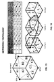
- each element of the entire network is surrounded by 6 others identical elements.
- the basic element is the hexagonal cell subdivided in 3 sectors with the BTS at the centre point.
- the basic element is composed with 3 hexagonal cells having the BTSs at the edge, each cell contains 3 sectors.
- each base element is periodic in time as the one of fig.10b.
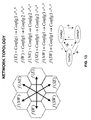
- Each element of the network has its own sequence (configuration) and it's necessary to create suitable relationships between all sequences in order to achieve maximum interference rejection. Moreover the relationships must respect topological properties so that they can be repeated periodically in space.
- each cloud represents the basic network element constituted by a single cell hexagon. It's possible to define functions that describe the spatial relationships between configurations of adjacent elements, in the figure one function is indicated as an arrow. For better understanding the liaisons that bind these functions their names are chosen according to geographic notations: East, West, North, South.
- f(E) means function that binds the configuration of one element with the configuration of the adjacent element at its East side, and so on.
- Each function has its "inverse" represented by the contrary path and named f(.) -1 ; the geometrical constraints lead to important equalities indicated in fig.12.
- An example of consistent functions f(.) is provided by observing the fig.13 (similar to fig.12).
- the name "+”, "-” written at the right side of each equation suggests the operation of moving along an imaginary ring (in the bottom of fig.13) closed by the time-space periodicity of any configuration. This presupposes frame synchronisation inside the cells of the whole network, or at least of the geographical area involved with the invention.
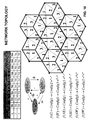
- the situation can be summarized with the tables of fig.14 or equivalently with the drawing in which the numbers positioned in each sector indicate the corresponding timeslot.
- Step 4) is always executed on-line, while steps 1), 2), and 3) are preferably performed off-line during the planning phase of the whole network, this because those steps directly impact the network architecture and an accurate study is needed.
- Certain networks support dynamic cell splitting to face sudden high traffic inside a limited area; in such a case the planning must consider also this feature.
- the main step consists of:
- the second step "Base element timetable setting" is introduced for selecting the temporal behaviour of the base element during all available timeslots.
- this item allows to produce a "configuration table” like the partial timetable visible on the top of the figure; note that because in this embodiment there are more than one cell in the base element, the configuration table has to be built up "from an interference rejection point of view”.
- a trick to proceed is to build the first row and then fill the others simply by shifting left (or right) the contents of the cells of the first row.
- the arrows in the table of fig.16 show the right shift (note that the TS2 of first row in column A3 goes to the first column A1 during the shift, as well as the TS3 of second row in column A3 jumps in first column A1; this behaviour highlights that this "shifting" has to be planned with a fixed period of N (3 in the example).
- the trick leads to get always a minimum of N rows in the table.
- each row of the table is represented by drawing one base element (hexagon in this example) and putting in each sector the number that indicates the timeslot it corresponds to, the arrows aid to follow the sequence.
- the interference rejection point of view it's useful to look at the *, #, x symbols in fig.16 imagining that they represent signal/s of an user or a group of users.
- the *, #, x users are transmitting (uplink) simultaneously and the interference rejection capabilities means that:
- the preceding fig.12 shows that for this new item it's sufficient to place the first tier of elements (6 elements) that surrounds the base one. Deploy the network means:
- Steps 3.1 and 3.2 are performed with reference to fig.18 which shows the base element surrounded with all its neighbours.
- step 3.1 the configuration 1 of the uppermost timetable in Figure is selected (it's the same table of fig.16) .
- step 3.2 the equalities in the f(.) functions define all necessary relationships, for example f(E) brings from "configX” to "configX+1", etc. Properties of such a network make easy to add elements wherever is needed by simply applying the appropriate functions.
- Fig.19 (similar to fig. 18) shows the simplest way to deploy the network, which is to define all functions as "Identities" where identity means no action, no change of configuration.
- N Number of timeslots considered UL or DL.
- the fourth main step is entered by other procedures and brings to other procedures, in accordance with its on-line nature. Suitable initiator procedures are: Admission Control, Channel Allocation, Handover, etc., while continuation procedures are the ones of Dedicated mode.
- the fourth main step is carried out through steps labelled F1 to F8.
- step F1 the BTS performs DOA measurements on each relevant signal received in uplink and previously synchronised; then step F2 is entered and the MS/UE is assigned to the sector best in agreement with the measured DOA.
- step F3 is devoted to the read of the configuration table (timetable) of the cell for finding the corresponding timeslot.
- This step and the successive are performed by the network element having in charge the timetable, usually the resource allocation is a centralised task charged to the BSC / RNC, or the MSC. From the MS/UE point of view the other network elements are considered as "the network”.
- the availability of the corresponding timeslot is checked in step F4.
- a first option exerted in F6 is to refuse the access to the MS/UE.
- a second option exerted in F7 is that to try the assignment of the timeslot allocated in the nearest sector. This option consists of switching to the configuration table of the nearest sector and repeating step F3 for finding the corresponding timeslot.
- a third option exerted in F8 is to generate a handover command for the MS/UE.
- FIG.23 shows a "photograph" of the users randomly allocated inside each respective 120° sectored cell.
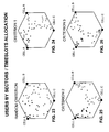
- the considered simulations are relevant to only three preferred criteria applied to the hexagonal base element of fig.15, as illustrated in the Figures 24, 25 and 26 , with the further bond that the selected criterion has to be applied in all the network.
- the only uplink direction is studied assuming symmetric traffic on three timeslots and sectored cell of 120° subdivided in three equal sized sectors.
- the modelled cells have different radii, namely: 0.3, 0.5, and 0.7 km. Each cell is charged with high traffic generated by 16 users per active timeslot per cell (48 simultaneous users per base element). The three criteria differ to each other only for the different choice of the sectors among the three cells. All the three choices are for achieving minimum interferences. Multi-User Detection (MUD) and Zero Forcing - Block Decision Feedback Equaliser (ZF-BDFE) are implemented in the receiver.
- Figures 24, 25 and 26 give three "photographs" of the user positions at the active timeslot according to the three studied allocation criteria, where clearly appears that in each cell the users are located inside a determined sector. The aim of simulations is not to evaluate the skill of an allocation criterion in respect to the others, but instead the one of giving an idea of the increasing of performances due to the application of the teaching of the invention.
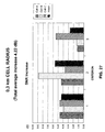
- fig.27 the simulation results are depicted in form of histograms relevant to Cell A, Cell B, and Cell C, all of 0.3 km radius, composing the hexagonal base element.
- Each histogram indicates dB of SNR (Signal-to-Noise Ratio) increase over the random case of fig.23. All the three allocation criteria are considered, and for each criterion a fourth histogram is added for indicating the average of the three. The average calculated on all the three criteria is 4.22 dB.
- Fig.28 is similar to the preceding Figure but relevant to cells of 0.5 km radius; the total average increase is 3.82 dB.
Priority Applications (2)
| Application Number | Priority Date | Filing Date | Title |
|---|---|---|---|
| EP03425122A EP1453337A1 (de) | 2003-02-27 | 2003-02-27 | Verfahren zur Funkressourcenverwaltung in zellularen Telefonnetzen basierend auf Interferenzverminderung, Zeitschlitzzuweisung und eine adaptative Antennengruppe |
| CNA2004100036635A CN1525782A (zh) | 2003-02-27 | 2004-02-05 | 蜂窝式电话网络中的无线电资源管理方法 |
Applications Claiming Priority (1)
| Application Number | Priority Date | Filing Date | Title |
|---|---|---|---|
| EP03425122A EP1453337A1 (de) | 2003-02-27 | 2003-02-27 | Verfahren zur Funkressourcenverwaltung in zellularen Telefonnetzen basierend auf Interferenzverminderung, Zeitschlitzzuweisung und eine adaptative Antennengruppe |
Publications (1)
| Publication Number | Publication Date |
|---|---|
| EP1453337A1 true EP1453337A1 (de) | 2004-09-01 |
Family
ID=32749048
Family Applications (1)
| Application Number | Title | Priority Date | Filing Date |
|---|---|---|---|
| EP03425122A Withdrawn EP1453337A1 (de) | 2003-02-27 | 2003-02-27 | Verfahren zur Funkressourcenverwaltung in zellularen Telefonnetzen basierend auf Interferenzverminderung, Zeitschlitzzuweisung und eine adaptative Antennengruppe |
Country Status (2)
| Country | Link |
|---|---|
| EP (1) | EP1453337A1 (de) |
| CN (1) | CN1525782A (de) |
Cited By (4)
| Publication number | Priority date | Publication date | Assignee | Title |
|---|---|---|---|---|
| WO2007087217A1 (en) * | 2006-01-23 | 2007-08-02 | Kyocera Corporation | System and method for adaptive assignment of unique words in a communication system |
| WO2009135745A1 (en) * | 2008-05-06 | 2009-11-12 | Alcatel Lucent | Method for allocating frequency subchannels on an air interface of a wireless communication system and corresponding radio resource allocation module |
| US8412249B2 (en) * | 2005-12-20 | 2013-04-02 | Alcatel Lucent | Resource allocation based on interference mitigation in a wireless communication system |
| EP2373109A4 (de) * | 2008-12-30 | 2016-07-06 | China Academy Of Telecomm Tech | Interferenzkoordinationsverfahren und zugangsnetzgerät |
Families Citing this family (14)
| Publication number | Priority date | Publication date | Assignee | Title |
|---|---|---|---|---|
| CN100471316C (zh) * | 2005-04-28 | 2009-03-18 | 北京邮电大学 | 在td-scdma系统中动态信道分配的方法 |
| CN101005653B (zh) * | 2006-01-16 | 2012-06-27 | 华为技术有限公司 | 基站自动进行资源选择、分配的方法和系统 |
| US8155659B2 (en) * | 2006-03-21 | 2012-04-10 | Telefonaktiebolaget L M Ericsson (Publ) | Measurement-assisted dynamic frequency-reuse in cellular telecommunications networks |
| CN101047683B (zh) * | 2006-05-16 | 2011-06-15 | 华为技术有限公司 | 一种无线信号发射/接收方法及发射/接收装置 |
| CN101175258B (zh) * | 2006-10-30 | 2011-09-14 | 华为技术有限公司 | 在无线通信系统中实现子帧创建的方法及基站及系统 |
| WO2009054763A1 (en) * | 2007-10-25 | 2009-04-30 | Telefonaktiebolaget Lm Ericsson (Publ) | A method of allocating radio resources |
| CN101472287B (zh) * | 2007-12-27 | 2010-12-08 | 华为技术有限公司 | 基于智能天线技术的通信系统组网方法及装置 |
| CN101489231B (zh) * | 2008-01-15 | 2010-09-29 | 上海贝尔阿尔卡特股份有限公司 | 无线通信网中小区间干扰抑制的控制方法和装置 |
| CN101720130B (zh) * | 2008-10-09 | 2012-10-03 | 电信科学技术研究院 | 一种分配物理资源块的方法和装置 |
| EP2656672B1 (de) | 2010-12-22 | 2015-08-26 | Nokia Solutions and Networks Oy | Zuweisung von ressourcen |
| CN102572857B (zh) * | 2012-01-12 | 2015-11-18 | 电信科学技术研究院 | 一种上行信道链路预算方法和设备 |
| WO2014101026A1 (zh) * | 2012-12-26 | 2014-07-03 | 华为技术有限公司 | 小区管理方法及系统 |
| US10616865B2 (en) * | 2015-08-14 | 2020-04-07 | Qualcomm Incorporated | Techniques for reporting radio resource management (RRM) measurements for a shared radio frequency spectrum band |
| CN115884381A (zh) * | 2021-09-27 | 2023-03-31 | 中兴通讯股份有限公司 | 干扰抑制方法、装置、基站及存储介质 |
Citations (3)
| Publication number | Priority date | Publication date | Assignee | Title |
|---|---|---|---|---|
| EP0963129A2 (de) * | 1998-06-01 | 1999-12-08 | Mitsubishi Denki Kabushiki Kaisha | Zellulares Layout mit gleichzeitiger Sektor- und Zeitschlitzauswahl |
| WO2001054301A2 (en) * | 2000-01-18 | 2001-07-26 | Nortel Networks Limited | Multi-beam antenna system with reduced cross-beam interference |
| EP1241906A2 (de) * | 2001-02-14 | 2002-09-18 | NTT DoCoMo, Inc. | Kommunikationsregelungsverfahren und Vorrichtung in einem Mobilfunksystem |
-
2003
- 2003-02-27 EP EP03425122A patent/EP1453337A1/de not_active Withdrawn
-
2004
- 2004-02-05 CN CNA2004100036635A patent/CN1525782A/zh active Pending
Patent Citations (3)
| Publication number | Priority date | Publication date | Assignee | Title |
|---|---|---|---|---|
| EP0963129A2 (de) * | 1998-06-01 | 1999-12-08 | Mitsubishi Denki Kabushiki Kaisha | Zellulares Layout mit gleichzeitiger Sektor- und Zeitschlitzauswahl |
| WO2001054301A2 (en) * | 2000-01-18 | 2001-07-26 | Nortel Networks Limited | Multi-beam antenna system with reduced cross-beam interference |
| EP1241906A2 (de) * | 2001-02-14 | 2002-09-18 | NTT DoCoMo, Inc. | Kommunikationsregelungsverfahren und Vorrichtung in einem Mobilfunksystem |
Cited By (9)
| Publication number | Priority date | Publication date | Assignee | Title |
|---|---|---|---|---|
| US8412249B2 (en) * | 2005-12-20 | 2013-04-02 | Alcatel Lucent | Resource allocation based on interference mitigation in a wireless communication system |
| WO2007087217A1 (en) * | 2006-01-23 | 2007-08-02 | Kyocera Corporation | System and method for adaptive assignment of unique words in a communication system |
| US7565151B2 (en) | 2006-01-23 | 2009-07-21 | Kyocera Corporation | System and method for adaptive assignment of unique words in a communication system |
| WO2009135745A1 (en) * | 2008-05-06 | 2009-11-12 | Alcatel Lucent | Method for allocating frequency subchannels on an air interface of a wireless communication system and corresponding radio resource allocation module |
| EP2129178A1 (de) * | 2008-05-06 | 2009-12-02 | Alcatel Lucent | Verfahren zur Zuweisung von Frequenzunterkanälen auf einer Luftschnittstelle eines drahtlosen Kommunikationssystems und entsprechendes Funkressourcenzuweisungsmodul |
| JP2011521544A (ja) * | 2008-05-06 | 2011-07-21 | アルカテル−ルーセント | ワイヤレス通信システムのエアインターフェース上の周波数副チャネルを割り振る方法、及び対応する無線資源割振りモジュール |
| US8958407B2 (en) | 2008-05-06 | 2015-02-17 | Alcatel Lucent | Method for allocating frequency subchannels on an air interface of a wireless communication system and corresponding radio resource allocation module |
| EP2373109A4 (de) * | 2008-12-30 | 2016-07-06 | China Academy Of Telecomm Tech | Interferenzkoordinationsverfahren und zugangsnetzgerät |
| US9894672B2 (en) | 2008-12-30 | 2018-02-13 | China Academy Of Telecommunications Technology | Method and access network device for interference coordination |
Also Published As
| Publication number | Publication date |
|---|---|
| CN1525782A (zh) | 2004-09-01 |
Similar Documents
| Publication | Publication Date | Title |
|---|---|---|
| EP1453337A1 (de) | Verfahren zur Funkressourcenverwaltung in zellularen Telefonnetzen basierend auf Interferenzverminderung, Zeitschlitzzuweisung und eine adaptative Antennengruppe | |
| US8655410B2 (en) | Beam wobbling for increased downlink coverage and capacity | |
| EP1433344B1 (de) | Verfahren und methoden dafür zur strahlformung in einer mehrpunkt kommunikationsumgebung | |
| CA2147312C (en) | Apparatus and method for dynamic resource allocation in wireless communication networks utilizing ordered borrowing | |
| TWI489806B (zh) | 用於使用主動天線陣列的虛擬扇區化之設備及方法 | |
| US6400697B1 (en) | Method and apparatus for sector based resource allocation in a broadhand wireless communications system | |
| EP1925172B1 (de) | Kommunikationsbetriebsmittel-zuteilungsverfahren einer basisstation | |
| US7894402B2 (en) | High rate packet data spatial division multiple access (SDMA) | |
| CA2253123A1 (en) | Dynamic resource allocation method and apparatus for broadband services in a wireless communications system | |
| WO2007066074A1 (en) | Point to multipoint device for communication with a plurality of telecommunications units | |
| Wang et al. | Interference coordination for millimeter wave communications in 5G networks for performance optimization | |
| EP1433345B1 (de) | System und entsprechende verfahren zum gruppieren von mehrpunktkommunikationszielen | |
| KR20150105987A (ko) | 이웃 탐색 신호들의 전력 제어 | |
| US9794040B2 (en) | Pilot signal resource allocation for a cellular MIMO system | |
| CN111817755A (zh) | 基站设备、通信方法和存储介质 | |
| EP1719378A1 (de) | Verfahren, system, vorrichtung und computerprogramm zum zuteilen von funkbetriebsmitteln in zellularen tdma-telekommunikationssystemen | |
| WO1996007284A1 (en) | A cellular telecommunications method and network | |
| US20070161376A1 (en) | Timeslot reuse for a service based interference control | |
| US7792532B1 (en) | Method and system of reusing walsh code to increase forward channel capacity | |
| Chuang et al. | Medium access control for advanced cellular internet services | |
| US20240129909A1 (en) | Carrier aggregation grouping based on user location in 5g nr massive mimo beamforming network | |
| US8929195B1 (en) | Method and system of reusing walsh codes to increase forward channel capacity | |
| Shi et al. | System capacity of 72 GHz mmWave transmission in hybrid networks | |
| US10455604B2 (en) | Regret benefit ratio link scheduler for wireless backhaul with directional antennas | |
| Wang | Resource Allocation on 5G Network with Inteference Mitigation |
Legal Events
| Date | Code | Title | Description |
|---|---|---|---|
| PUAI | Public reference made under article 153(3) epc to a published international application that has entered the european phase |
Free format text: ORIGINAL CODE: 0009012 |
|
| AK | Designated contracting states |
Kind code of ref document: A1 Designated state(s): AT BE BG CH CY CZ DE DK EE ES FI FR GB GR HU IE IT LI LU MC NL PT SE SI SK TR |
|
| AX | Request for extension of the european patent |
Extension state: AL LT LV MK RO |
|
| AKX | Designation fees paid | ||
| REG | Reference to a national code |
Ref country code: DE Ref legal event code: 8566 |
|
| STAA | Information on the status of an ep patent application or granted ep patent |
Free format text: STATUS: THE APPLICATION IS DEEMED TO BE WITHDRAWN |
|
| 18D | Application deemed to be withdrawn |
Effective date: 20050302 |