EP1453239B1 - Verfahren zur Übertragung von Paketen mit zwei verschiedenen Leitungscodes und geeigneter Sender und Empfänger - Google Patents
Verfahren zur Übertragung von Paketen mit zwei verschiedenen Leitungscodes und geeigneter Sender und Empfänger Download PDFInfo
- Publication number
- EP1453239B1 EP1453239B1 EP03290481A EP03290481A EP1453239B1 EP 1453239 B1 EP1453239 B1 EP 1453239B1 EP 03290481 A EP03290481 A EP 03290481A EP 03290481 A EP03290481 A EP 03290481A EP 1453239 B1 EP1453239 B1 EP 1453239B1
- Authority
- EP
- European Patent Office
- Prior art keywords
- receiver
- data sequence
- encoding
- synchronization
- encoding scheme
- Prior art date
- Legal status (The legal status is an assumption and is not a legal conclusion. Google has not performed a legal analysis and makes no representation as to the accuracy of the status listed.)
- Expired - Lifetime
Links
Images




Classifications
-
- H—ELECTRICITY
- H04—ELECTRIC COMMUNICATION TECHNIQUE
- H04J—MULTIPLEX COMMUNICATION
- H04J3/00—Time-division multiplex systems
- H04J3/22—Time-division multiplex systems in which the sources have different rates or codes
-
- H—ELECTRICITY
- H04—ELECTRIC COMMUNICATION TECHNIQUE
- H04L—TRANSMISSION OF DIGITAL INFORMATION, e.g. TELEGRAPHIC COMMUNICATION
- H04L25/00—Baseband systems
- H04L25/38—Synchronous or start-stop systems, e.g. for Baudot code
- H04L25/40—Transmitting circuits; Receiving circuits
- H04L25/49—Transmitting circuits; Receiving circuits using code conversion at the transmitter; using predistortion; using insertion of idle bits for obtaining a desired frequency spectrum; using three or more amplitude levels ; Baseband coding techniques specific to data transmission systems
- H04L25/4904—Transmitting circuits; Receiving circuits using code conversion at the transmitter; using predistortion; using insertion of idle bits for obtaining a desired frequency spectrum; using three or more amplitude levels ; Baseband coding techniques specific to data transmission systems using self-synchronising codes, e.g. split-phase codes
-
- H—ELECTRICITY
- H04—ELECTRIC COMMUNICATION TECHNIQUE
- H04L—TRANSMISSION OF DIGITAL INFORMATION, e.g. TELEGRAPHIC COMMUNICATION
- H04L7/00—Arrangements for synchronising receiver with transmitter
- H04L7/04—Speed or phase control by synchronisation signals
-
- H—ELECTRICITY
- H04—ELECTRIC COMMUNICATION TECHNIQUE
- H04L—TRANSMISSION OF DIGITAL INFORMATION, e.g. TELEGRAPHIC COMMUNICATION
- H04L7/00—Arrangements for synchronising receiver with transmitter
- H04L7/04—Speed or phase control by synchronisation signals
- H04L7/041—Speed or phase control by synchronisation signals using special codes as synchronising signal
-
- H—ELECTRICITY
- H04—ELECTRIC COMMUNICATION TECHNIQUE
- H04J—MULTIPLEX COMMUNICATION
- H04J14/00—Optical multiplex systems
- H04J14/08—Time-division multiplex systems
Definitions
- the invention relates to a method for transmitting packets comprising a synchronization part and a payload part.
- a method is known from the US patent application US 6,064,705 disclosing an encoding system using transmission packets including a start of frame followed by the coded data value followed by the end of frame where the start of packet encoding and the end of packet encoding is different from the data value encoding.
- Optical networks face increasing bandwidth demands and diminishing fiber availability. Based on the emergence of the optical layer in transport network optical networks provide higher capacity and reduced cost. As with any new technology, many challenges arise. Bit synchronization and power adaptation at when receiving packetized data require a bit synchronization sequence. This necessity of a bit synchronization sequence results in a limitation in throughput and/or in flexibility when transmitting short packets like Internet packets.
- This encoding should be suited to encode data compact as well as suited for the data transport layer down through the physical layer, i.e. the optical medium and the used components.
- Non-return to zero encoding is commonly used in slow speed communications interfaces for both synchronous and asynchronous transmission. Using NRZ, a logic 1 bit is sent as a high value and a logic 0 bit is sent as a low value, illustrated in figure 1.
- Ethernet for example, there is no control over the number of 1's or 0's which may sent consecutively. There could potentially be thousands of 1's or 0's in sequence. If the encoded data contains long 'runs' of logic 1's or 0's, this does not result in any bit transitions. The lack of transitions prevents the receiver from reliably regenerating the clock making it impossible to detect the boundaries of the received bits at the receiver. This is the reason why Manchester coding is used e.g. in Ethernet LANs.
- Manchester encoding is a synchronous clock encoding technique often used in the physical layer to encode the clock and data of a synchronous bit stream.
- the actual binary data to be transmitted are not sent as a sequence of logic 1's and 0's. Instead, the bits are translated into a slightly different format that has a number of advantages over using straight binary encoding.
- Manchester encoding follows the rule that an original logic 0 is encoded by a 0 to 1 change (upward transition at bit center), and a logic 1 is encoded by a 1 to 0 change (downward transition at bit center).
- the diagram in the background teaching figure 1 shows a time diagram where the bit sequence 1,1,0,1,0,0,1,1 is in the upper part A Manchester encoded and NRZ encoded in the lower part B.
- Manchester encoding may be alternatively viewed as a phase encoding where each bit is encoded by a positive 90 degree phase transition, or a negative 90 degree phase transition.
- the Manchester code is therefore also known as a Bi-phase Code.
- a Manchester encoded signal contains frequent level transitions which allow the receiver to extract the clock signal using e.g. a digital phase locked loop (DPLL) and correctly decode the value and timing of each bit.
- DPLL digital phase locked loop
- the transmitted bit stream must contain a high density of bit transitions. Manchester encoding ensures this, allowing the receiving DPLL to correctly extract the clock signal.
- the penalty for introducing frequent transitions, is that the Manchester coded signal consumes more bandwidth than the NRZ encoded signal.
- the signal spectrum lies between the 5 and 10 MHz.
- Manchester encoding is used as the physical layer of an Ethernet LAN, where the additional bandwidth is not a significant issue.
- the pattern of bits 0, 1, 1, 1, 1, 0, 0, 1 encodes to 01, 10, 10, 10, 10, 01, 01, 10.
- Another more curious example is the pattern 1, 0, 1, 0, 1 which encodes to 10, 01, 10, 01, 10 which could also be viewed as "1 00 11 00 11 0 ".
- the preamble sequence encodes to a 5 MHz square wave i.e., one half cycle in each 0.1 microsecond bit period.
- Line coding is a process of modifying a source signal to facilitate proper signal reception in the presence of transmission impairments.
- the required features of line codes are bit sequence independence, small low frequency content, transmission of adequate timing information, high efficiency, low error multiplication, and low systematic jitter etc. Since currently all practical systems employ optical intensity modulation, the line code is essentially unipolar.
- binary line codes are preferred to multilevel codes due to the inherent non-linearity of the optical media.
- a typical optical transmitter consists of a digital device providing the data or payload.
- the data is encoded and serialized for driving a laser or modulator to get a modulated laser beam, i.e. serialization and electrical-to-optical conversion.
- the receiver reverses this operation, i.e. optical-to-electrical conversion and de-serialization, with similar limitations, i.e. the speed limit of the participating components.
- the invention acts on the preamble of the independent method claim for transmitting packets having a synchronization part and a payload part, sending a synchronization part, detecting the synchronization part and synchronizing and adapting the receiver for receiving the payload part.
- the transients in the receiver have lower bounds. It has to be large enough not causing transients by regular data patterns. There is a relationship between data rate, transient times, and the length of bit synchronization sequence.
- bit synchronization sequence is lost in terms of throughput, and when it is of fix length, the smaller the packets the larger the percentage of loss.
- the change of the transient time needs to be completed within the timeframe of the bit synchronization sequence, producing a new timing limitation.
- the change or switch of the transient time is initiated by a detector recognizing the start of a packet. That is the reason why the bit synchronization sequence cannot be shorter than the delay in the start of packet detection path.
- This invention targets the problem of improving the (asynchronous and synchronous) coding tradeoff for burst transmission and burst switching.
- Bit synchronization and power adaptation at packet start require a bit synchronization sequence.
- the necessity of a bit synchronization sequence results in a limitation in throughput and/or in flexibility when transmitting short packets.
- Switchable timing of the receiver having the disadvantage of a control signal for the time constant switch causing a timing limitation for the bit synchronization sequence. This is good for large packets, where the throughput is major target.
- the adaptation and the decoding might be depended on the received signal pattern or might be time depended.
- the second encoding might comprises further encodings.
- Another advantage of the present invention is to transmit very long packets or even infinitary packets with a throughput that is close to the bit rate, as after the initial parts the rest of the packet is e.g. NRZ-encoded.
- a further advantage of the present invention is that the control path time delay and the corresponding robustness reserve for this delay are no more in the critical path for the first relevant data bits. Even packets shorter than this delay time can be received.
- the invention is to use multiple encodings, one for a trailer and one for the rest.
- the invention is a packet format comprising a very short bit synchronization sequence, followed by e.g., Manchester encoded data for a certain timeframe, necessary to do the timing switching, and followed by the rest of the data, e.g. in normal NRZ coding.
- the Manchester coding of the first section is preferably to be performed in a way, that one Manchester coded bit is mapped into a timeframe of 2 bits of the normal NRZ signal.
- the Manchester coding can be done in the digital device at low bit rates. Hence there is no need for coding operations in the high frequency part.
- the upper frequency bound of the sequential signal is the same for both the Manchester coded as well as the NRZ coded part. Hence there is no need for bandwidth extension.
- the Manchester coded section is nearly free of lower frequency components. This allows for short time constants in the receiver for the bit synchronization sequence and the during the Manchester coded data section. Hence no need for time critical switch of time constants before any relevant data bit. The benefit is paid by only the half throughput compared to the bit rate during the trailer transmission.
- the switch of the timing compared to the bit rate, is rather a smooth transit.
- the switch of the timing is rather a smooth transit.
- For its implementation are not only sample and hold gates available but also gain controlled amplifiers etc.
- FIG. 2 shows a serialized packet P over the time axis T.
- the serialized packet P comprises a bit synchronization sequence sync comprising a robustness reserve rob, and a data sequence dat, e.g. header and payload of an Internet packet.
- the packet receiving process is illustrated by the numeric labels 1,2,3,4 on the time axis T corresponding to times.
- the serialized packet arrives at the receiver.
- the receiver detects the start of the packet P and derives the signal characteristics, e.g. phase, clock, and intensity.
- the receiver Within the time interval spanned by the bit synchronization sequence sync and the robustness reserve rob, in the example at the second label 2 the receiver has adapted or is calibrated to the signal characteristics, e.g. the timing of the receiver.
- the adapting has to be finished at the third label 3 when the data sequence dat starts. Then the receiver has to decode the transmitted data until the packet ends, at the fourth label 4.
- the figure further illustrates the shortest possible packet by the arrow labels sp, comprising the bit synchronization sequence sync, the robustness reserve and a small data sequence.
- FIG. 3 shows a serialized packet P' over the time axis T according to the invention.
- the serialized packet P' comprises a bit synchronization sequence sync', followed by a first data sequence dat1 comprising a robustness reserve rob', and followed by a second data sequence dat2.
- the packet receiving process is illustrated by the numeric labels 1',2',3',4',5', and 6' on the time axis T corresponding to time stamps.
- the serialized packet arrives at a receiver.
- the receiver detects the start of the packet P' and adapts to the signal characteristics, e.g. phase, clock, and intensity, encoding, etc.
- the receiver Within the time interval spanned by the bit synchronization sequence sync', in the example at the second label 2' the receiver has adapted according to the signal characteristics, e.g. the timing of the receiver etc.
- a lazy adapting has to be finished at the third label 3' when the first data sequence dat1 starts.
- the receiver has the to decode the transmitted data until the first data sequence dat1 ends at label 5'.
- the receiver might further adapt characteristics, enabled by the coding of dat1 .
- the receiver has to be adapted on the receiving characteristics, in the example at label 4', say.
- the receiver starts decoding the second data sequence dat2 until the packet ends, at label 6'.
- the figure further illustrates the shortest possible packet by the arrow labels sp', comprising the bit synchronization sequence sync', a small first data sequence dat1.
- FIG. 4 shows a schematic drawing of a optical transmission system comprising a sending unit S, a sender control unit SC, an electrical-to-optical converter C1, an optical-to-electrical converter C2, a receiving unit R, a packet detector unit PD, and a receiver control unit RC.
- the sending unit S has to encode a sending data stream IN into signals driving the electrical-to-optical converter C1. Therefore the sending unit S needs to be controlled by the sender control unit SC instructing the sender e.g. how to encode a data packet, i.e. translating a piece of data into a deliver format as described in figure 3.
- the electrical-to-optical converter C1 translates the signal into an optical signal which is the transmitted to the optical-to-electrical converter C2.
- the optical-to-electrical converter C2 translates the received optical signal, changed by transport phenomena like chromatic dispersion and attenuation, into an electrical signal for the receiving unit R.
- the receiver needs to interpret the electrical signal in such a way that the original piece of data is reconstructed and delivered through a receiving data stream OUT.
- the receiver and the sender need to share an encoding schema.
- Using the serialized packet format described in figure 3 enables the packet detector unit PD recognizing the start of a packet sequence.
- the packet detector unit PD informs the receiver control unit RC about a packet start event and signal deformations, e.g. by analyzing the synchronization sequence seq' described in figure 3.
- the receiver control unit RC is enabled to control the receiving unit, e.g. adapting timing, amplitude level(s), phase shift, etc., and especially the de-coding accordingly.
- control unit is especially enabled to adapt the decoding at the time labels 2' and 5' ensuring that the first data sequence dat1 is decoded using a first decoding and the second data sequence dat2 is decoded using a second decoding.
- Figure. 5 shows a timing diagram comparing the encoding of a sample data sequence 1,1,0,1,0,0,1,1,1,0,1 using the serialized packet formats described in figure 2 and figure 3.
- the synchronization sequence 1,0,1,0,1,0,1,0 is assumed.
- the upper part of the time diagram shows a plain non-return to zero encoding according to the description of figure 2.
- the time axis T is divided into sections indicated by vertical dashed lines. Within one section the non-return to zero encoding encoded signal is constant high or low.
- the resulting signal Seq has a synchronization sequence (prefix) sync consisting of four alternating consecutive high section low section pairs.
- This synchronization sequence (prefix) sync comprises a robustness reserve rob, and is followed by the data sequence dat encoded into the section level sequence high, high, low, high, low, low , high, high, high, low, high. According to the rule that an '1' is translated into high section and a '0' is translated into low section.
- the lower part of the time diagram shows an encoding according to the description of figure 3, i.e. a application of the invention.
- the time axis T is divided into sections indicated by the vertical dashed lines.
- the synchronization sequence sync' and the first data sequence dat1 e.g. a packet header
- the resulting signal Seq' has a shortened synchronization sequence (prefix) sync' consisting of two alternating consecutive sections.
- This synchronization sequence (prefix) sync' is followed by the first data sequence dat1 comprising the bit sequence 1,1,0,1 in Manchester encoding, i.e. falling edge section, falling edge section, raising edge section, falling edge section.
- the first data sequence dat1 comprises a robustness reserve rob', and is followed by a second data sequence dat2 encoded into the section level sequence low, low, high, high, high, low, high, according to the non-return to zero encoding.
- the diagram illustrates the advantages of the invention, namely that short packets are faster transmitted.
- the Manchester coding of the prefix is performed such that a Manchester coded bit is mapped into a two sections or timeframe of 2 bits of the non-return to zero coded part.
- This coding schema especially has following advantageous features:
- the Manchester coding can be done in the digital device at low bit rates.
- the upper frequency bound of the sequential signal is the same for both the Manchester coded as well as the NRZ coded part.
- the Manchester coded section is nearly free of lower frequency components. This allows for short time constants in the receiver not only during the bit synchronization sequence but also during the Manchester coded data section.
- the benefit costs only the half throughput compared to the bit rate during the header section.
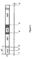
- Figure. 6 shows a spectral power characteristics diagram illustrating adaptation of the receiver characteristics for non-return to zero encoded signals and Manchester encoded signals illustrated by the right-arrow labeled F.
- the x-axis of the diagram is the normalized frequency.
- the y-axis of the diagram is the spectral power illustrated by the up-arrow labeled E.
- the characteristic for non-return to zero encoding is labeled N and the characteristic for Manchester encoding is labeled M.
- Manchester coding and NRZ are only examples for codlings. Instead of Manchester coding any other coding schema can be applied that produces a reasonable band gap at lower frequencies. Instead of pure NRZ code any other coding schema can be applied that results in a high channel utilization.
Landscapes
- Engineering & Computer Science (AREA)
- Computer Networks & Wireless Communication (AREA)
- Signal Processing (AREA)
- Multimedia (AREA)
- Physics & Mathematics (AREA)
- Spectroscopy & Molecular Physics (AREA)
- Synchronisation In Digital Transmission Systems (AREA)
- Optical Communication System (AREA)
- Small-Scale Networks (AREA)
- Dc Digital Transmission (AREA)
Claims (8)
- Verfahren zur Übertragung von Paketen von einem Sender zu einem Empfänger, die einen Synchronisationsteil (sync) und einen Nutzdatenteil (dat) umfassen, wobei der Nutzdatenteil (dat) eine erste Datensequenz (dat1) umfasst, gefolgt von einer zweiten Datensequenz (dat2), der Empfänger einen Decoder umfasst, wobei das Verfahren die Schritte umfasst desauf der Senderseite (S) undSendens eines synchronisationsteils (sync) unter Verwendung eines ersten Codierverfahrens, gefolgt vomSenden und Codieren der ersten Datensequenz (dat1) unter Verwendung des ersten Codierverfahrens,Codierens und Sendens der zweiten Datensequenz (dat2) unter Verwendung eines zweiten Codierverfahrens
Detektierens des Synchronisationnteils (sync) und Bitsynchronisierens und Anpassens des Empfängers und Decoders und Empfangens und Decodierens der ersten Datensequenz,Empfangens und Decodierens der zweiten Datensequenz auf der Empfangerseite (R),Anpassens des Empfängers und Decoders und
dadurch gekennzeichnet, dass
das erste Codierverfahren eine Manchester-Leitungscodierunq ist, die eine wirksame Synchronisation ermöglicht, wobei die Bitsynchronisation basierend auf dem Synchronisationsteil und mindestens der ersten Datensequenz vorgenommen wird und wobei das zweite Codierverfahren eine Codierung ohne Nulldurchgang ist, die geringe Bandbreitenanforderungen unterstützt. - Verfahren nach Anspruch 1, dadurch gekennzeichnet, dass die Anpassung und die Decodierung vom empfangenen Signalmuster abhängt.
- Verfahren nach Anspruch 1, dadurch gekennzeichnet, dass die Anpassung und die Decodierung zeitabhängig ist.
- Verfahren nach Anspruch 1, dadurch gekennzeichnet, dass die zweite Codierung weitere Codierungen umfasst.
- Sender (S, C1, SC) zur Übertragung von Paketen zu einem Empfänger, wobei die Pakete einen Synchronisationsteil (sync) umfassen, gefolgt von einem Nutzdatenteil (dat), wobei der Nutzdatenteil (dat) eine erste Datensequenz (dat1) umfasst, gefolgt von einer zweiten Datensequenz (dat2), wobei der Sender eine Serialisierungseinheit zum Serialisieren von Daten und eine Codierungseinheit zum Codieren serialisierter Daten umfasst, wobei die Serialisierungeinheit ausgeführt ist, den Synchronisationsteil (sync') unter Verwendung eines ersten Codierverfahrens zu generieren, gefolgt von der ersten Datensequenz (dat1) unter Verwendung des ersten Codierverfahrens, gefolgt von der zweiten Datensequenz (dat2) unter Verwendung eines zweiten Codierverfahrens, dadurch gekennzeichnet, dass das erste Codierverfahren eine Manchester-Leitungscodierung ist, die am Empfänger eine wirksame Synchronisation ermöglicht, wobei die Bitsynchronisation basierend auf dem Synchronisationsteil und mindestens der ersten Datensequenz vorgenommen werden könnte, und wobei das zweite Codierverfahren eine Codierung ohne Nulldurchgang ist, die geringe Bandbreitenanforderungen unterstützt.
- Empfänger (C2, PD, RC, R) zum Empfangen von Paketen, die einen Synchronisationsteil (sync) umfassen, gefolgt von einem Nutzdatenteil (dat), wobei der Nutzdatenteil (dat) eine erste Datensequenz (dat1) umfasst, gefolgt von einer zweiten Datensequenz (dat2), wobei der Empfänger eine Detektoreinheit (PD) zum Detektieren des Synchronisationsteil (sync'), der in einem ersten Codierverfahren codiert ist, und eine steuereinheit (RC) zur Bitsynchronisierung und Anpassung der Empfängercharakteristika umfasst, und der Empfänger einen Decoder (R) umfasst, der ausgeführt ist, um die erste Datensequenz (dat1) zu decodieren, die in dem ersten Codierverfahren codiert ist, wobei die Detektoreinheit (PD) ausgeführt ist, um das Ende der ersten Datensequenz (4') zu detektieren, wobei die Steuereinheit (RC) ausgeführt ist, um den Decoder zum Decodieren der zweiten Datensequenz (dat2) des Nutzdatenteils anzupassen, die in einem zweiten Codierverfahren codiert ist, dadurch gekennzeichnet, dass das erste Codierverfahren eine Manchester-Leitungscodierung ist, die eine wirksame Synchronisation ermöglicht, wobei die Bitsynchronisation basierend auf dem Synchronisationsteil und mindestens der ersten Datensequenz vorgenommen wird, und wobei das zweite Codierverfahren eine Codierung ohne Nulldurchgang ist, die geringe Bandbreitenanforderungen unterstützt.
- Optisches Vernetzungselement zur Übertragung von Paketen, die einen synchronisationsteil (sync) und einen Nutzdatenteil (dat) umfassen, wobei das optische Vernetzungselement einen Sender nach Anspruch 6 umfasst.
- Optisches Vernetzungselement zur Übertragung von Paketen, die einen Synchronisationsteil (sync') und einen Nutzdatenteil (dat1, dat2) umfassen, wobei das optische Vernetzungselement einen Empfänger nach Anspruch 7 umfasst.
Priority Applications (4)
| Application Number | Priority Date | Filing Date | Title |
|---|---|---|---|
| AT03290481T ATE303024T1 (de) | 2003-02-28 | 2003-02-28 | Verfahren zur übertragung von paketen mit zwei verschiedenen leitungscodes und geeigneter sender und empfänger |
| DE60301384T DE60301384T2 (de) | 2003-02-28 | 2003-02-28 | Verfahren zur Übertragung von Paketen mit zwei verschiedenen Leitungscodes und geeigneter Sender und Empfänger |
| EP03290481A EP1453239B1 (de) | 2003-02-28 | 2003-02-28 | Verfahren zur Übertragung von Paketen mit zwei verschiedenen Leitungscodes und geeigneter Sender und Empfänger |
| US10/773,168 US7340022B2 (en) | 2003-02-28 | 2004-02-09 | Method, a sender, a receiver, an optical network element and a serialized packet format for transmitting packets |
Applications Claiming Priority (1)
| Application Number | Priority Date | Filing Date | Title |
|---|---|---|---|
| EP03290481A EP1453239B1 (de) | 2003-02-28 | 2003-02-28 | Verfahren zur Übertragung von Paketen mit zwei verschiedenen Leitungscodes und geeigneter Sender und Empfänger |
Publications (2)
| Publication Number | Publication Date |
|---|---|
| EP1453239A1 EP1453239A1 (de) | 2004-09-01 |
| EP1453239B1 true EP1453239B1 (de) | 2005-08-24 |
Family
ID=32748996
Family Applications (1)
| Application Number | Title | Priority Date | Filing Date |
|---|---|---|---|
| EP03290481A Expired - Lifetime EP1453239B1 (de) | 2003-02-28 | 2003-02-28 | Verfahren zur Übertragung von Paketen mit zwei verschiedenen Leitungscodes und geeigneter Sender und Empfänger |
Country Status (4)
| Country | Link |
|---|---|
| US (1) | US7340022B2 (de) |
| EP (1) | EP1453239B1 (de) |
| AT (1) | ATE303024T1 (de) |
| DE (1) | DE60301384T2 (de) |
Cited By (1)
| Publication number | Priority date | Publication date | Assignee | Title |
|---|---|---|---|---|
| US8770685B2 (en) | 2009-02-22 | 2014-07-08 | Hewlett-Packard Development Company, L.P. | Logical and virtual nozzle-fire-restart-line for fluid-ejection device |
Families Citing this family (12)
| Publication number | Priority date | Publication date | Assignee | Title |
|---|---|---|---|---|
| ATE328384T1 (de) | 2004-07-15 | 2006-06-15 | Cit Alcatel | Laserwellenlängensteuerung in einem wdm-system |
| US20060047862A1 (en) * | 2004-09-02 | 2006-03-02 | International Business Machines Corporation | Automatic hardware data link initialization |
| US7532822B2 (en) | 2005-02-28 | 2009-05-12 | Nortel Networks Limited | Clock recovery from an optical signal with polarization impairments |
| US7606498B1 (en) | 2005-10-21 | 2009-10-20 | Nortel Networks Limited | Carrier recovery in a coherent optical receiver |
| US7522841B2 (en) | 2005-10-21 | 2009-04-21 | Nortel Networks Limited | Efficient data transmission and training of data processing functions |
| US7555227B2 (en) | 2005-10-21 | 2009-06-30 | Nortel Networks Limited | Polarization compensation in a coherent optical receiver |
| FR2899742B1 (fr) * | 2006-04-05 | 2008-07-04 | Alcatel Sa | Procede de codage d'un signal binaire |
| KR101066351B1 (ko) | 2007-01-05 | 2011-09-20 | 삼성전자주식회사 | 통신 시스템에서 데이터 송수신 시스템 및 방법 |
| KR101115520B1 (ko) * | 2008-12-23 | 2012-02-27 | 전자부품연구원 | 자기장 기반의 저주파 대역(~300㎑) 무선통신의 물리계층 구성 방법 및 이 방법을 실행하는 프로그램이 기록되어 컴퓨터로 읽을 수 있는 기록매체 |
| DE102010029349A1 (de) * | 2010-05-27 | 2011-12-01 | Robert Bosch Gmbh | Steuereinheit zum Austausch von Daten mit einer Peripherieeinheit, Peripherieeinheit, und Verfahren zum Datenaustausch |
| EP3639419B1 (de) * | 2017-06-16 | 2024-07-24 | Motorola Mobility LLC | Verfahren und vorrichtung zur herstellung einer vielzahl von synchronisationssignalsequenzen für die verwendung mit einem oder mehreren kommunikationszielen |
| US11606150B2 (en) * | 2020-06-23 | 2023-03-14 | Infinera Corporation | Data synchronization in optical networks and devices |
Family Cites Families (8)
| Publication number | Priority date | Publication date | Assignee | Title |
|---|---|---|---|---|
| JPH0691523B2 (ja) * | 1989-06-02 | 1994-11-14 | 株式会社ケンウッド | フレーム同期方式 |
| JP2933133B2 (ja) * | 1997-01-28 | 1999-08-09 | 日本電気株式会社 | ディジタル映像信号多重方式および分離方式 |
| US6064705A (en) | 1997-08-20 | 2000-05-16 | Sarnoff Corporation | Manchester encoding and decoding system |
| JP3344934B2 (ja) * | 1997-10-17 | 2002-11-18 | 沖電気工業株式会社 | データ受信装置 |
| DE69719573T2 (de) * | 1997-11-18 | 2003-12-11 | International Business Machines Corp., Armonk | Verfahren und vorrichtung zur verbesserten schnurrlosen optischen kommunikation |
| EP1189374B1 (de) * | 2000-09-18 | 2009-09-02 | Lucent Technologies Inc. | Rahmensynchronisierung in einem Datenkommunikationssystem |
| DE10100500A1 (de) | 2001-01-08 | 2002-07-11 | Alcatel Sa | Verfahren zur digitalen Nachrichtenübertragung |
| US20040136455A1 (en) * | 2002-10-29 | 2004-07-15 | Akhter Mohammad Shahanshah | Efficient bit stream synchronization |
-
2003
- 2003-02-28 EP EP03290481A patent/EP1453239B1/de not_active Expired - Lifetime
- 2003-02-28 DE DE60301384T patent/DE60301384T2/de not_active Expired - Fee Related
- 2003-02-28 AT AT03290481T patent/ATE303024T1/de not_active IP Right Cessation
-
2004
- 2004-02-09 US US10/773,168 patent/US7340022B2/en not_active Expired - Fee Related
Cited By (1)
| Publication number | Priority date | Publication date | Assignee | Title |
|---|---|---|---|---|
| US8770685B2 (en) | 2009-02-22 | 2014-07-08 | Hewlett-Packard Development Company, L.P. | Logical and virtual nozzle-fire-restart-line for fluid-ejection device |
Also Published As
| Publication number | Publication date |
|---|---|
| EP1453239A1 (de) | 2004-09-01 |
| US7340022B2 (en) | 2008-03-04 |
| DE60301384T2 (de) | 2006-03-09 |
| ATE303024T1 (de) | 2005-09-15 |
| DE60301384D1 (de) | 2005-09-29 |
| US20040170242A1 (en) | 2004-09-02 |
Similar Documents
| Publication | Publication Date | Title |
|---|---|---|
| EP1453239B1 (de) | Verfahren zur Übertragung von Paketen mit zwei verschiedenen Leitungscodes und geeigneter Sender und Empfänger | |
| US7149256B2 (en) | Multilevel pulse position modulation for efficient fiber optic communication | |
| US8026836B2 (en) | Transmission of pathological data patterns | |
| US5612956A (en) | Reformatting of variable rate data for fixed rate communication | |
| US20010028686A1 (en) | Serial line synchronization method and apparatus | |
| US7240271B2 (en) | Transmitting data words | |
| US4663767A (en) | Optical data bus having a statistical access method | |
| CA2085395A1 (en) | Routing and switching of high-speed data with the header transmitted on a subcarrier frequency | |
| US20040196920A1 (en) | Wireless RF link for uncompressed transmission of HDTV signals | |
| US6404819B1 (en) | System and method for generating NRZ signals from RZ signals in communications networks | |
| US8032916B2 (en) | Single master clock control of Ethernet data transfer over both a cable TV return path and an Ethernet forward path | |
| WO2005057970A1 (ja) | 局間伝送方法及び無線基地局監視方法並びにその方法を用いた装置 | |
| US7415089B2 (en) | High-speed serial link clock and data recovery | |
| US20030016760A1 (en) | Binary transmitter and method of transmitting data in binary format | |
| EP4239911B1 (de) | Passives optisches netzwerk mit flexibler rate unter verwendung von verzögerungsmodulation | |
| US7260151B2 (en) | Dual phase pulse modulation system | |
| US7539245B2 (en) | System and method for digital transmission and modulation of conjugate pulse position | |
| US20030002572A1 (en) | Method and system for sample and recreation synchronization for digital transmission of analog modem signal | |
| CN111082875A (zh) | 激光通信装置及方法 | |
| JP3838087B2 (ja) | 光通信システム及び光通信装置 | |
| US6944212B2 (en) | Method and apparatus for the spectrally efficient encoding and decoding of discrete data into and from analog waveforms | |
| CN115865271A (zh) | 一种e波段毫米波点到点传输方法及装置 | |
| KR20030020519A (ko) | 코드 검출을 이용한 선로부호의 듀얼모드 부호화/복호화장치 및 그 방법 | |
| JPH06338878A (ja) | デジタル通信システム | |
| JP2005504485A (ja) | 送信信号中の連続的なスペースの最大数を減少させる符号化機能を有する赤外線通信システム |
Legal Events
| Date | Code | Title | Description |
|---|---|---|---|
| PUAI | Public reference made under article 153(3) epc to a published international application that has entered the european phase |
Free format text: ORIGINAL CODE: 0009012 |
|
| 17P | Request for examination filed |
Effective date: 20031114 |
|
| AK | Designated contracting states |
Kind code of ref document: A1 Designated state(s): AT BE BG CH CY CZ DE DK EE ES FI FR GB GR HU IE IT LI LU MC NL PT SE SI SK TR |
|
| AX | Request for extension of the european patent |
Extension state: AL LT LV MK RO |
|
| GRAP | Despatch of communication of intention to grant a patent |
Free format text: ORIGINAL CODE: EPIDOSNIGR1 |
|
| RTI1 | Title (correction) |
Free format text: METHOD OF TRANSMITTING PACKETS WITH TWO DIFFERENT LINE CODES AND SUITABLE SENDER AND RECEIVER |
|
| AKX | Designation fees paid |
Designated state(s): AT BE BG CH CY CZ DE DK EE ES FI FR GB GR HU IE IT LI LU MC NL PT SE SI SK TR |
|
| GRAS | Grant fee paid |
Free format text: ORIGINAL CODE: EPIDOSNIGR3 |
|
| GRAA | (expected) grant |
Free format text: ORIGINAL CODE: 0009210 |
|
| AK | Designated contracting states |
Kind code of ref document: B1 Designated state(s): AT BE BG CH CY CZ DE DK EE ES FI FR GB GR HU IE IT LI LU MC NL PT SE SI SK TR |
|
| PG25 | Lapsed in a contracting state [announced via postgrant information from national office to epo] |
Ref country code: NL Free format text: LAPSE BECAUSE OF FAILURE TO SUBMIT A TRANSLATION OF THE DESCRIPTION OR TO PAY THE FEE WITHIN THE PRESCRIBED TIME-LIMIT Effective date: 20050824 Ref country code: CH Free format text: LAPSE BECAUSE OF FAILURE TO SUBMIT A TRANSLATION OF THE DESCRIPTION OR TO PAY THE FEE WITHIN THE PRESCRIBED TIME-LIMIT Effective date: 20050824 Ref country code: BE Free format text: LAPSE BECAUSE OF FAILURE TO SUBMIT A TRANSLATION OF THE DESCRIPTION OR TO PAY THE FEE WITHIN THE PRESCRIBED TIME-LIMIT Effective date: 20050824 Ref country code: LI Free format text: LAPSE BECAUSE OF FAILURE TO SUBMIT A TRANSLATION OF THE DESCRIPTION OR TO PAY THE FEE WITHIN THE PRESCRIBED TIME-LIMIT Effective date: 20050824 Ref country code: FI Free format text: LAPSE BECAUSE OF FAILURE TO SUBMIT A TRANSLATION OF THE DESCRIPTION OR TO PAY THE FEE WITHIN THE PRESCRIBED TIME-LIMIT Effective date: 20050824 Ref country code: SK Free format text: LAPSE BECAUSE OF FAILURE TO SUBMIT A TRANSLATION OF THE DESCRIPTION OR TO PAY THE FEE WITHIN THE PRESCRIBED TIME-LIMIT Effective date: 20050824 Ref country code: CZ Free format text: LAPSE BECAUSE OF FAILURE TO SUBMIT A TRANSLATION OF THE DESCRIPTION OR TO PAY THE FEE WITHIN THE PRESCRIBED TIME-LIMIT Effective date: 20050824 Ref country code: SI Free format text: LAPSE BECAUSE OF FAILURE TO SUBMIT A TRANSLATION OF THE DESCRIPTION OR TO PAY THE FEE WITHIN THE PRESCRIBED TIME-LIMIT Effective date: 20050824 Ref country code: AT Free format text: LAPSE BECAUSE OF FAILURE TO SUBMIT A TRANSLATION OF THE DESCRIPTION OR TO PAY THE FEE WITHIN THE PRESCRIBED TIME-LIMIT Effective date: 20050824 |
|
| REG | Reference to a national code |
Ref country code: GB Ref legal event code: FG4D |
|
| REG | Reference to a national code |
Ref country code: CH Ref legal event code: EP |
|
| REG | Reference to a national code |
Ref country code: IE Ref legal event code: FG4D |
|
| REF | Corresponds to: |
Ref document number: 60301384 Country of ref document: DE Date of ref document: 20050929 Kind code of ref document: P |
|
| PG25 | Lapsed in a contracting state [announced via postgrant information from national office to epo] |
Ref country code: BG Free format text: LAPSE BECAUSE OF FAILURE TO SUBMIT A TRANSLATION OF THE DESCRIPTION OR TO PAY THE FEE WITHIN THE PRESCRIBED TIME-LIMIT Effective date: 20051124 Ref country code: GR Free format text: LAPSE BECAUSE OF FAILURE TO SUBMIT A TRANSLATION OF THE DESCRIPTION OR TO PAY THE FEE WITHIN THE PRESCRIBED TIME-LIMIT Effective date: 20051124 Ref country code: SE Free format text: LAPSE BECAUSE OF FAILURE TO SUBMIT A TRANSLATION OF THE DESCRIPTION OR TO PAY THE FEE WITHIN THE PRESCRIBED TIME-LIMIT Effective date: 20051124 Ref country code: DK Free format text: LAPSE BECAUSE OF FAILURE TO SUBMIT A TRANSLATION OF THE DESCRIPTION OR TO PAY THE FEE WITHIN THE PRESCRIBED TIME-LIMIT Effective date: 20051124 |
|
| PG25 | Lapsed in a contracting state [announced via postgrant information from national office to epo] |
Ref country code: ES Free format text: LAPSE BECAUSE OF FAILURE TO SUBMIT A TRANSLATION OF THE DESCRIPTION OR TO PAY THE FEE WITHIN THE PRESCRIBED TIME-LIMIT Effective date: 20051205 |
|
| PG25 | Lapsed in a contracting state [announced via postgrant information from national office to epo] |
Ref country code: PT Free format text: LAPSE BECAUSE OF FAILURE TO SUBMIT A TRANSLATION OF THE DESCRIPTION OR TO PAY THE FEE WITHIN THE PRESCRIBED TIME-LIMIT Effective date: 20060124 |
|
| NLV1 | Nl: lapsed or annulled due to failure to fulfill the requirements of art. 29p and 29m of the patents act | ||
| PG25 | Lapsed in a contracting state [announced via postgrant information from national office to epo] |
Ref country code: HU Free format text: LAPSE BECAUSE OF FAILURE TO SUBMIT A TRANSLATION OF THE DESCRIPTION OR TO PAY THE FEE WITHIN THE PRESCRIBED TIME-LIMIT Effective date: 20060225 |
|
| PG25 | Lapsed in a contracting state [announced via postgrant information from national office to epo] |
Ref country code: MC Free format text: LAPSE BECAUSE OF NON-PAYMENT OF DUE FEES Effective date: 20060228 Ref country code: LU Free format text: LAPSE BECAUSE OF NON-PAYMENT OF DUE FEES Effective date: 20060228 Ref country code: IE Free format text: LAPSE BECAUSE OF NON-PAYMENT OF DUE FEES Effective date: 20060228 |
|
| REG | Reference to a national code |
Ref country code: CH Ref legal event code: PL |
|
| ET | Fr: translation filed | ||
| PLBE | No opposition filed within time limit |
Free format text: ORIGINAL CODE: 0009261 |
|
| STAA | Information on the status of an ep patent application or granted ep patent |
Free format text: STATUS: NO OPPOSITION FILED WITHIN TIME LIMIT |
|
| 26N | No opposition filed |
Effective date: 20060526 |
|
| REG | Reference to a national code |
Ref country code: IE Ref legal event code: MM4A |
|
| PGFP | Annual fee paid to national office [announced via postgrant information from national office to epo] |
Ref country code: DE Payment date: 20070216 Year of fee payment: 5 Ref country code: GB Payment date: 20070216 Year of fee payment: 5 |
|
| PGFP | Annual fee paid to national office [announced via postgrant information from national office to epo] |
Ref country code: IT Payment date: 20070622 Year of fee payment: 5 |
|
| PGFP | Annual fee paid to national office [announced via postgrant information from national office to epo] |
Ref country code: FR Payment date: 20070212 Year of fee payment: 5 |
|
| PG25 | Lapsed in a contracting state [announced via postgrant information from national office to epo] |
Ref country code: EE Free format text: LAPSE BECAUSE OF FAILURE TO SUBMIT A TRANSLATION OF THE DESCRIPTION OR TO PAY THE FEE WITHIN THE PRESCRIBED TIME-LIMIT Effective date: 20050824 |
|
| PG25 | Lapsed in a contracting state [announced via postgrant information from national office to epo] |
Ref country code: TR Free format text: LAPSE BECAUSE OF FAILURE TO SUBMIT A TRANSLATION OF THE DESCRIPTION OR TO PAY THE FEE WITHIN THE PRESCRIBED TIME-LIMIT Effective date: 20050824 |
|
| GBPC | Gb: european patent ceased through non-payment of renewal fee |
Effective date: 20080228 |
|
| PG25 | Lapsed in a contracting state [announced via postgrant information from national office to epo] |
Ref country code: CY Free format text: LAPSE BECAUSE OF FAILURE TO SUBMIT A TRANSLATION OF THE DESCRIPTION OR TO PAY THE FEE WITHIN THE PRESCRIBED TIME-LIMIT Effective date: 20050824 |
|
| REG | Reference to a national code |
Ref country code: FR Ref legal event code: ST Effective date: 20081031 |
|
| PG25 | Lapsed in a contracting state [announced via postgrant information from national office to epo] |
Ref country code: DE Free format text: LAPSE BECAUSE OF NON-PAYMENT OF DUE FEES Effective date: 20080902 |
|
| PG25 | Lapsed in a contracting state [announced via postgrant information from national office to epo] |
Ref country code: FR Free format text: LAPSE BECAUSE OF NON-PAYMENT OF DUE FEES Effective date: 20080229 |
|
| PG25 | Lapsed in a contracting state [announced via postgrant information from national office to epo] |
Ref country code: GB Free format text: LAPSE BECAUSE OF NON-PAYMENT OF DUE FEES Effective date: 20080228 |
|
| PG25 | Lapsed in a contracting state [announced via postgrant information from national office to epo] |
Ref country code: IT Free format text: LAPSE BECAUSE OF NON-PAYMENT OF DUE FEES Effective date: 20080228 |