EP1453210A1 - Radio transmission device and radio transmission method - Google Patents
Radio transmission device and radio transmission method Download PDFInfo
- Publication number
- EP1453210A1 EP1453210A1 EP03723250A EP03723250A EP1453210A1 EP 1453210 A1 EP1453210 A1 EP 1453210A1 EP 03723250 A EP03723250 A EP 03723250A EP 03723250 A EP03723250 A EP 03723250A EP 1453210 A1 EP1453210 A1 EP 1453210A1
- Authority
- EP
- European Patent Office
- Prior art keywords
- digital signal
- amplification
- power
- section
- gain
- Prior art date
- Legal status (The legal status is an assumption and is not a legal conclusion. Google has not performed a legal analysis and makes no representation as to the accuracy of the status listed.)
- Withdrawn
Links
Images


Classifications
-
- H—ELECTRICITY
- H04—ELECTRIC COMMUNICATION TECHNIQUE
- H04W—WIRELESS COMMUNICATION NETWORKS
- H04W52/00—Power management, e.g. Transmission Power Control [TPC] or power classes
- H04W52/04—Transmission power control [TPC]
- H04W52/18—TPC being performed according to specific parameters
- H04W52/28—TPC being performed according to specific parameters using user profile, e.g. mobile speed, priority or network state, e.g. standby, idle or non-transmission
-
- H—ELECTRICITY
- H03—ELECTRONIC CIRCUITRY
- H03G—CONTROL OF AMPLIFICATION
- H03G3/00—Gain control in amplifiers or frequency changers
- H03G3/20—Automatic control
- H03G3/30—Automatic control in amplifiers having semiconductor devices
- H03G3/3036—Automatic control in amplifiers having semiconductor devices in high-frequency amplifiers or in frequency-changers
- H03G3/3042—Automatic control in amplifiers having semiconductor devices in high-frequency amplifiers or in frequency-changers in modulators, frequency-changers, transmitters or power amplifiers
- H03G3/3047—Automatic control in amplifiers having semiconductor devices in high-frequency amplifiers or in frequency-changers in modulators, frequency-changers, transmitters or power amplifiers for intermittent signals, e.g. burst signals
-
- H—ELECTRICITY
- H04—ELECTRIC COMMUNICATION TECHNIQUE
- H04B—TRANSMISSION
- H04B1/00—Details of transmission systems, not covered by a single one of groups H04B3/00 - H04B13/00; Details of transmission systems not characterised by the medium used for transmission
- H04B1/69—Spread spectrum techniques
- H04B1/707—Spread spectrum techniques using direct sequence modulation
-
- H—ELECTRICITY
- H04—ELECTRIC COMMUNICATION TECHNIQUE
- H04W—WIRELESS COMMUNICATION NETWORKS
- H04W52/00—Power management, e.g. Transmission Power Control [TPC] or power classes
- H04W52/04—Transmission power control [TPC]
- H04W52/18—TPC being performed according to specific parameters
- H04W52/22—TPC being performed according to specific parameters taking into account previous information or commands
- H04W52/228—TPC being performed according to specific parameters taking into account previous information or commands using past power values or information
-
- H—ELECTRICITY
- H04—ELECTRIC COMMUNICATION TECHNIQUE
- H04W—WIRELESS COMMUNICATION NETWORKS
- H04W52/00—Power management, e.g. Transmission Power Control [TPC] or power classes
- H04W52/04—Transmission power control [TPC]
- H04W52/30—Transmission power control [TPC] using constraints in the total amount of available transmission power
- H04W52/32—TPC of broadcast or control channels
- H04W52/322—Power control of broadcast channels
-
- H—ELECTRICITY
- H04—ELECTRIC COMMUNICATION TECHNIQUE
- H04W—WIRELESS COMMUNICATION NETWORKS
- H04W52/00—Power management, e.g. Transmission Power Control [TPC] or power classes
- H04W52/04—Transmission power control [TPC]
- H04W52/52—Transmission power control [TPC] using AGC [Automatic Gain Control] circuits or amplifiers
Definitions
- the present invention relates to a radio transmitting apparatus and radio transmitting method in a radio communication system.
- a conventional radio transmitting apparatus modulates, spreads, multiplexes, and performs gain adjustment on transmit data, executes predetermined radio processing such as D/A conversion, the performs attenuation and radio transmission from an antenna.
- This object is achieved by means of a radio transmitting apparatus that fixes the gain to be multiplied by a transmit signal prior to execution of radio processing at a given value when transmit digital signal power enters a fluctuating state due to the transmission of a burst signal such as a PDSCH signal.
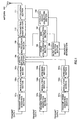
- FIG.1 is a block diagram showing an example of the configuration of a radio transmitting apparatus according to Embodiment 1 of the present invention.
- a CDMA Code Division Multiple Access
- transmit frame generation sections 101a, 101b, and 101c generate transmit frames from transmit data 1, transmit data 2, and transmit data 3.
- Modulation sections 102a, 102b, and 102c perform modulation processing on the generated transmit signals and generate modulated signals.
- Spreading sections 103a, 103b, and 103c perform spreading processing on these modulated signals.
- a multiplexing section 104 multiplexes the spread modulated signals output by spreading sections 103a, 103b, and 103c.
- Apower calculation section 105 calculates the power of the multiplex signal output from multiplexing section 104.
- Aburst signal detection section 106 detects whether or not the transmit signal is a burst signal from fluctuation of the calculated signal power value, and outputs the detection result to a gain calculation section 107 and attenuation amount calculation section 108.
- Gain calculation section 107 calculates gain to be multiplied by the transmit signal based on the detection result reported from burst signal detection section 106 and the signal power calculated by power calculation section 105, and outputs this calculated gain to a gain multiplication section 109 and attenuation amount calculation section 108.
- Attenuation amount calculation section 108 calculates an attenuation amount based on the detection result reported from burst signal detection section 106 and the gain calculated by gain calculation section 107, and outputs this calculated attenuation amount to an attenuation section 111.
- Gain multiplication section 109 multiplies the multiplex signal output from multiplexing section 104 by the gain calculated by gain calculation section 107.
- a transmitting radio section 110 executes predetermined radio processing such as orthogonal modulation on the signal after gain multiplication.
- Attenuation section 111 attenuates the signal output from transmitting radio section 110, using the attenuation amount calculated by attenuation amount calculation section 108.
- An antenna 112 transmits this radio signal.
- a feature of the present invention is that the gain by which multiplication is performed by gain multiplication section 109 and the attenuation amount used by attenuation section 111 differ according to whether a burst signal is detected or not detected by burst signal detection section 106.
- a feature of the present invention is that when a burst signal is detected, the gain by which multiplication is performed by gain multiplication section 109 and the attenuation amount used by attenuation section 111 are made fixed values.
- Burst signal detection section 106 counts the number of times power fluctuation occurs in a certain fixed observation period for the power calculated by power calculation section 105, and indirectly counts the number of times a situation arises in which the attenuation amount is switched by attenuation section 111 in line with power fluctuation. Then, if this number of switching times is greater than or equal to a preset threshold value, burst signal detection section 106 determines that the transmit signal is a burst signal, and outputs a detection result to the effect that a burst signal has been detected to gain calculation section 107 and attenuation amount calculation section 108.
- burst signal detection section 106 determines that the transmit signal is not a burst signal, and outputs a detection result to the effect that a burst signal has not been detected to gain calculation section 107 and attenuation amount calculation section 108.
- burst signal detection section 106 determines that the transmit signal is not a burst signal.
- Gain calculation section 107 calculates gain whereby the power of the signal input to transmitting radio section 110 is kept within a fixed range, based on the power calculated by power calculation section 105, and outputs this calculated gain to gain multiplication section 109 and attenuation amount calculation section 108.
- Gain multiplication section 109 multiplies the multiplex signal output from multiplexing section 104 by the gain calculated by gain calculation section 107, amplifies the power, and outputs the resulting signal to transmitting radio section 110.
- Attenuation amount calculation section 108 calculates an attenuation amount corresponding to the gain calculated by gain calculation section 107, and outputs this calculated attenuation amount to attenuation section 111. For example, if the gain calculated by gain calculation section 107 is 10 dB, the attenuation amount will also be 10 dB.
- Attenuation section 111 attenuates the signal output from transmitting radio section 110 using the attenuation amount calculated by attenuation amount calculation section 108, and transmits the resulting signal from antenna 112.
- burst signal detection section 106 determines that the transmit signal is a burst signal.
- gain calculation section 107 On receiving a detection result from burst signal detection section 106 to the effect that a burst signal has been detected, gain calculation section 107 outputs fixed gain to gain multiplication section 109 and attenuation amount calculation section 108.
- the lowest gain may be selected from a plurality of gain values calculated by gain calculation section 107 in line with power fluctuation within the above-described power fluctuation observation period.
- gain values of 10 dB, 12 dB, and 15 dB are calculated, the fixed gain will be the lowest value of 10 dB.
- burst signal detection section 106 stops burst signal detection. By this means, erroneous detection of a burst signal can be prevented with certainty.
- Attenuation amount calculation section 108 The operation of attenuation amount calculation section 108, gain multiplication section 109, and attenuation section 111 is the same as in the case where burst signal detection section 106 determines that the transmit signal is not a burst signal, as described above.
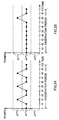
- FIG.2A and FIG.2B are drawings showing transmit signal power fluctuation and attenuation amount switching.
- a solid line indicates transmit signal power
- dotted lines indicate attenuation switching thresholds when attenuation amounts are designated ATT1, ATT2, and ATT3.
- gain calculation section 107 gain is determined according to the transmit signal power value calculated by power calculation section 105. Together with this, in attenuation amount calculation section 108, an attenuation amount is calculated according to the gain output from gain calculation section 107. For example, in FIG.2A, the power value at time t1 is in the range of attenuation amount ATT2, and therefore the attenuation amount is calculated as ATT2, while at time t2 the power value is in the range of attenuation amount ATT3, and therefore the attenuation amount is calculated as ATT3.
- the threshold value for the number of switching times preset in burst signal detection section 106 is 4.
- switching from ATT2 to ATT3, or switching from ATT3 to ATT2 occurs a total of 6 times during the observation period (0 to t10). Therefore, in this case, since the number of switchovers exceeds the threshold number of 4, a detection result to the effect that a burst signal has been detected is output to gain calculation section 107 and attenuation amount calculation section 108 from burst signal detection section 106 at the point at which observation ends (t10).
- transmit signal power values are observed over a predetermined period in order that gain is not adjusted in reaction to a transitory power fluctuation, thereby enabling a burst signal to be detected with good precision.
- burst signal detection it is also possible to detect that the transmit signal is a burst signal at the instant at which the number of attenuation amount switchovers due to signal power fluctuation exceeds a predetermined threshold.
- a detection result to the effect that a burst signal has been detected is output to gain calculation section 107 and attenuation amount calculation section 108 from burst signal detection section 106 at the instant at which the number of power fluctuations reaches the threshold value of 4 - that is, at point t6.
- the transmit signal is not a burst signal if, after a burst signal is detected, the attenuation amount due to signal power fluctuation is not switched consecutively for a predetermined number of times - that is to say, if the attenuation amount is not switched for a given period.
- the transmit signal is not a burst signal if the attenuation amount is not switched consecutively 6 times.
- a detection result to the effect that a burst signal has not been detected is output to gain calculation section 107 and attenuation amount calculation section 108 from burst signal detection section 106 at point t5.
- the fact that transmit digital signal power enters a fluctuating state is determined by means of various determination methods, gain is fixed at a given value when amplifying a transmit signal prior to executing radio processing, and the attenuation amount is fixed at a given value when a transmit signal is attenuated after radio processing has been executed, thereby enabling excessive gain switching operations to be suppressed, and enabling modulation precision degradation and adjacent channel leakage power ratio degradation to be suppressed.
- burst signal detection result is output to gain calculation section 107 and attenuation amount calculation section 108, but if it is so arranged that attenuation amount calculation section 108 always uses the reciprocal of the gain detected by gain calculation section 107, the burst signal detection result may be output only to gain calculation section 107.
- burst signal detection is determined according to the number of times the attenuation amount is switched, but burst signal detection may also be determined according to the number of times gain is switched.
- FIG.3 is a block diagram showing an example of the configuration of a radio transmitting apparatus according to Embodiment 2 of the present invention.
- This radio transmitting apparatus has the same basic configuration as the radio transmitting apparatus shown in FIG.1, and therefore configuration elements identical to those in FIG.1 are assigned the same codes as in FIG.1 and descriptions thereof are omitted.
- a feature of this embodiment is that burst signal detection is performed from a spread modulated signal.
- spreading sections 103a, 103b, and 103c perform spread modulation processingon modulated signals, output the resulting signals to multiplexing section 104, and at the same time output transmit data transmission power settings to a burst signal detection section 201.
- Burst signal detection section 201 observes signal power fluctuation from the transmission power settings output from spreading sections 103a, 103b, and 103c, and detect whether or not the transmit signal is a burst signal. Operation after a burst signal is detected is the same as in Embodiment 1.
- FIG.4 is a block diagram showing an example of the configuration of a radio transmitting apparatus according to Embodiment 3 of the present invention.
- This radio transmitting apparatus has the same basic configuration as the radio transmitting apparatus shown in FIG.1, and therefore configuration elements identical to those in FIG.1 are assigned the same codes as in FIG.1 and descriptions thereof are omitted.
- a feature of this embodiment is that an IIR (Infinite Impulse Response) filter is provided instead of a burst signal detection section.
- IIR Infinite Impulse Response
- IIR filter 301 executes IIR filter processing on signal power calculated by power calculation section 105, and outputs the result to gain calculation section 107. Subsequent processing is the same as in Embodiment 1.
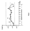
- FIG. 5 is a drawing for explaining the effect produced on transmit signal power by IIR filter processing. Transmit signal S1 input to IIR filter 301 becomes signal S2 after IIR filter processing. The meaning of the dotted lines is the same as in FIG.2.
- the transmit signal By traversing IIR filter 301, the transmit signal is smoothed. It can be seen, for example, that transmit signal power decreases at t3 and t5, falling below the ATT2 and ATT3 switching thresholds.
- Embodiment 1 can also be implemented in combination with Embodiment 1 or Embodiment 2.
- a radio transmitting apparatus can be installed in a communication terminal apparatus, by which means it is possible to provide a communication terminal apparatus that has the same kind of effects as described above.
- the present invention it is possible to suppress excessive gain switching operations associated with transmit digital signal power fluctuation, and suppress modulation precision degradation and adjacent channel leakage power ratio degradation.
- the present invention is applicable to a base station apparatus of a mobile communication system employing a CDMA method, etc.
Landscapes
- Engineering & Computer Science (AREA)
- Computer Networks & Wireless Communication (AREA)
- Signal Processing (AREA)
- Transmitters (AREA)
- Mobile Radio Communication Systems (AREA)
- Digital Transmission Methods That Use Modulated Carrier Waves (AREA)
Abstract
A power calculation section (105) calculates the
power of a transmit signal that has passed through transmit
frame generation sections (101a through 101c), modulation
sections (102a through 102c), spreading sections (103a
through 103c), and a multiplexing section (104). A burst
signal detection section (106) detects a burst signal
fromthispower. Againcalculationsection (107) outputs
fixed gain when a burst signal is detected. An
attenuation amount calculation section (108) calculates
an attenuation amount based on the gain calculated by
the gain calculation section (107). The transmit signal
is subjected to multiplication by the aforementioned gain
in a gain multiplication section (109), predetermined
radio processing in a transmitting radio section (110),
and attenuation processing in accordance with the
aforementioned attenuation amount in an attenuation
section (111), and is transmitted from an antenna (112).
By this means, it is possible to suppress excessive gain
switching operations, and suppress modulation precision
degradation and adjacent channel leakage power ratio
degradation.
Description
The present invention relates to a radio
transmitting apparatus and radio transmitting method in
a radio communication system.
A conventional radio transmitting apparatus
modulates, spreads, multiplexes, and performs gain
adjustment on transmit data, executes predetermined radio
processing such as D/A conversion, the performs
attenuation and radio transmission from an antenna.
However, with a conventional apparatus, when the
transmit signal is a burst signal such as a PDSCH (Physical
Downlink Shared Channel) signal, transmit signal power
fluctuation occurs frequently, and there are large
fluctuations in the amount of gain adjustment prior to
executing radio processing. A problem at this time is
that instantaneous interruption of the transmit signal
associated with gain switching frequently occurs,
modulation precision is degraded, and the adjacent
channel leakage power ratio is degraded.
It is an object of the present invention to suppress
excessive gain switching operations associated with
transmit digital signal power fluctuation, and suppress
modulation precision degradation and adjacent channel
leakage power ratio degradation.
This object is achieved by means of a radio
transmitting apparatus that fixes the gain to be
multiplied by a transmit signal prior to execution of
radio processing at a given value when transmit digital
signal power enters a fluctuating state due to the
transmission of a burst signal such as a PDSCH signal.
With reference now to the accompanying drawings,
embodiments of the present invention will be explained
in detail below.
FIG.1 is a block diagram showing an example of the
configuration of a radio transmitting apparatus according
to Embodiment 1 of the present invention. Here, by way
of example, a case is described in which a CDMA (Code
Division Multiple Access) radio transmitting apparatus
is installed in a base station apparatus.
In FIG.1, transmit frame generation sections 101a,
101b, and 101c generate transmit frames from transmit
data 1, transmit data 2, and transmit data 3. Modulation
sections 102a, 102b, and 102c perform modulation
processing on the generated transmit signals and generate
modulated signals. Spreading sections 103a, 103b, and
103c perform spreading processing on these modulated
signals. A multiplexing section 104 multiplexes the
spread modulated signals output by spreading sections
103a, 103b, and 103c.
Attenuation amount calculation section 108
calculates an attenuation amount based on the detection
result reported from burst signal detection section 106
and the gain calculated by gain calculation section 107,
and outputs this calculated attenuation amount to an
attenuation section 111.
Power amplification and power attenuation
operations of the radio transmitting apparatus that has
the above configuration will now be described in detail.
A feature of the present invention is that the gain
by which multiplication is performed by gain
multiplication section 109 and the attenuation amount
used by attenuation section 111 differ according to
whether a burst signal is detected or not detected by
burst signal detection section 106. In other words, a
feature of the present invention is that when a burst
signal is detected, the gain by which multiplication is
performed by gain multiplication section 109 and the
attenuation amount used by attenuation section 111 are
made fixed values.
Burst signal detection section 106 counts the number
of times power fluctuation occurs in a certain fixed
observation period for the power calculated by power
calculation section 105, and indirectly counts the number
of times a situation arises in which the attenuation amount
is switched by attenuation section 111 in line with power
fluctuation. Then, if this number of switching times is
greater than or equal to a preset threshold value, burst
signal detection section 106 determines that the transmit
signal is a burst signal, and outputs a detection result
to the effect that a burst signal has been detected to
gain calculation section 107 and attenuation amount
calculation section 108. On the other hand, if the number
of switching times is less than the preset threshold value,
burst signal detection section 106 determines that the
transmit signal is not a burst signal, and outputs a
detection result to the effect that a burst signal has
not been detected to gain calculation section 107 and
attenuation amount calculation section 108.
First, operation will be described for the case where
burst signal detection section 106 determines that the
transmit signal is not a burst signal.
Attenuation amount calculation section 108
calculates an attenuation amount corresponding to the
gain calculated by gain calculation section 107, and
outputs this calculated attenuation amount to attenuation
section 111. For example, if the gain calculated by gain
calculation section 107 is 10 dB, the attenuation amount
will also be 10 dB.
When a burst signal is not detected, according to
the above configuration, gain that is in accordance with
the power calculated by power calculation section 105
is used, and gain adjustment is performed before executing
radio processing, enabling the dynamic range of
transmitting radio section 110 to be used efficiently.
Next, operation will be described for the case where
burst signal detection section 106 determines that the
transmit signal is a burst signal.
On receiving a detection result from burst signal
detection section 106 to the effect that a burst signal
has been detected, gain calculation section 107 outputs
fixed gain to gain multiplication section 109 and
attenuation amount calculation section 108.
For example, as fixed gain, the lowest gain may be
selected from a plurality of gain values calculated by
gain calculation section 107 in line with power
fluctuation within the above-described power fluctuation
observation period. When gain values of 10 dB, 12 dB,
and 15 dB are calculated, the fixed gain will be the lowest
value of 10 dB. By this means it is possible to prevent
gain from being set excessively high, and excessive input
to transmitting radio section 110 can be prevented.
Also, when it is known beforehand by means of
broadcast information that there is no power fluctuation,
burst signal detection section 106 stops burst signal
detection. By this means, erroneous detection of a burst
signal can be prevented with certainty.
The operation of attenuation amount calculation
section 108, gain multiplication section 109, and
attenuation section 111 is the same as in the case where
burst signal detection section 106 determines that the
transmit signal is not a burst signal, as described above.
FIG.2A and FIG.2B are drawings showing transmit
signal power fluctuation and attenuation amount switching.
Here, a solid line indicates transmit signal power, and
dotted lines indicate attenuation switching thresholds
when attenuation amounts are designated ATT1, ATT2, and
ATT3.
In gain calculation section 107, gain is determined
according to the transmit signal power value calculated
by power calculation section 105. Together with this,
in attenuation amount calculation section 108, an
attenuation amount is calculated according to the gain
output from gain calculation section 107. For example,
in FIG.2A, the power value at time t1 is in the range
of attenuation amount ATT2, and therefore the attenuation
amount is calculated as ATT2, while at time t2 the power
value is in the range of attenuation amount ATT3, and
therefore the attenuation amount is calculated as ATT3.
Let us assume, for example, that the threshold value
for the number of switching times preset in burst signal
detection section 106 is 4. In this case, in FIG.2A,
switching from ATT2 to ATT3, or switching from ATT3 to
ATT2, occurs a total of 6 times during the observation
period (0 to t10). Therefore, in this case, since the
number of switchovers exceeds the threshold number of
4, a detection result to the effect that a burst signal
has been detected is output to gain calculation section
107 and attenuation amount calculation section 108 from
burst signal detection section 106 at the point at which
observation ends (t10).
In FIG.2B, switching from ATT2 to ATT3, or switching
from ATT3 to ATT2, occurs a total of twice during the
observation period. Therefore, in this case, since the
number of switchovers is less than the threshold number
of 4, a detection result to the effect that a burst signal
has not been detected is output to gain calculation section
107 and attenuation amount calculation section 108 from
burst signal detection section 106 at the point at which
observation ends (t10).
According to the above configuration, transmit
signal power values are observed over a predetermined
period in order that gain is not adjusted in reaction
to a transitory power fluctuation, thereby enabling a
burst signal to be detected with good precision.
In burst signal detection, it is also possible to
detect that the transmit signal is a burst signal at the
instant at which the number of attenuation amount
switchovers due to signal power fluctuation exceeds a
predetermined threshold. In this case, for example, in
FIG. 2A a detection result to the effect that a burst signal
has been detected is output to gain calculation section
107 and attenuation amount calculation section 108 from
burst signal detection section 106 at the instant at which
the number of power fluctuations reaches the threshold
value of 4 - that is, at point t6. By this means, the
fact that power is in a fluctuating state is determined
promptly at the point at which the number of transmit
signal power value fluctuations becomes greater than or
equal to the threshold value, thereby enabling detection
in which even momentary power fluctuations are tracked.
It is also possible to determine that the transmit
signal is not a burst signal if, after a burst signal
is detected, the attenuation amount due to signal power
fluctuation is not switched consecutively for a
predetermined number of times - that is to say, if the
attenuation amount is not switched for a given period.
For example, in FIG.2B, let us assume that it is to be
determined that the transmit signal is not a burst signal
if the attenuation amount is not switched consecutively
6 times. In this case, a detection result to the effect
that a burst signal has not been detected is output to
gain calculation section 107 and attenuation amount
calculation section 108 from burst signal detection
section 106 at point t5. By this means, the fact that
the transmit signal is not a burst signal can be detected
instantaneously when a burst signal ceases to be
transmitted.
Thus, according to this embodiment, the fact that
transmit digital signal power enters a fluctuating state
is determined by means of various determination methods,
gain is fixed at a given value when amplifying a transmit
signal prior to executing radio processing, and the
attenuation amount is fixed at a given value when a transmit
signal is attenuated after radio processing has been
executed, thereby enabling excessive gain switching
operations to be suppressed, and enabling modulation
precision degradation and adjacent channel leakage power
ratio degradation to be suppressed.
A case has here been described, by way of example,
in which three transmit data are multiplexed and
transmitted, but the number of multiplexed transmit data
is not limited to this, and may be four or more.
Also, a case has here been described, by way of
example, in which a burst signal detection result is output
to gain calculation section 107 and attenuation amount
calculation section 108, but if it is so arranged that
attenuation amount calculation section 108 always uses
the reciprocal of the gain detected by gain calculation
section 107, the burst signal detection result may be
output only to gain calculation section 107.
Moreover, a case has here been described, by way
of example, in which burst signal detection is determined
according to the number of times the attenuation amount
is switched, but burst signal detection may also be
determined according to the number of times gain is
switched.
FIG.3 is a block diagram showing an example of the
configuration of a radio transmitting apparatus according
to Embodiment 2 of the present invention. This radio
transmitting apparatus has the same basic configuration
as the radio transmitting apparatus shown in FIG.1, and
therefore configuration elements identical to those in
FIG.1 are assigned the same codes as in FIG.1 and
descriptions thereof are omitted.
A feature of this embodiment is that burst signal
detection is performed from a spread modulated signal.
In FIG.3, spreading sections 103a, 103b, and 103c
perform spread modulation processingon modulated signals,
output the resulting signals to multiplexing section 104,
and at the same time output transmit data transmission
power settings to a burst signal detection section 201.
Burst signal detection section 201 observes signal
power fluctuation from the transmission power settings
output from spreading sections 103a, 103b, and 103c, and
detect whether or not the transmit signal is a burst signal.
Operation after a burst signal is detected is the same
as in Embodiment 1.
By this means, it is determined directly from a
transmit signal prior to transmission power measurement
whether or not the signal is associated with power
fluctuation, thereby enabling power fluctuation to be
measured more accurately. Also, since determination is
possible without waiting for power measurement, power
fluctuation determination can be carried out rapidly,
especially in cases where totalization time is necessary
for power measurement.
FIG.4 is a block diagram showing an example of the
configuration of a radio transmitting apparatus according
to Embodiment 3 of the present invention. This radio
transmitting apparatus has the same basic configuration
as the radio transmitting apparatus shown in FIG.1, and
therefore configuration elements identical to those in
FIG.1 are assigned the same codes as in FIG.1 and
descriptions thereof are omitted.
A feature of this embodiment is that an IIR (Infinite
Impulse Response) filter is provided instead of a burst
signal detection section.
In FIG.4, IIR filter 301 executes IIR filter
processing on signal power calculated by power
calculation section 105, and outputs the result to gain
calculation section 107. Subsequent processing is the
same as in Embodiment 1.
FIG. 5 is a drawing for explaining the effect produced
on transmit signal power by IIR filter processing.
Transmit signal S1 input to IIR filter 301 becomes signal
S2 after IIR filter processing. The meaning of the dotted
lines is the same as in FIG.2.
By traversing IIR filter 301, the transmit signal
is smoothed. It can be seen, for example, that transmit
signal power decreases at t3 and t5, falling below the
ATT2 and ATT3 switching thresholds.
It can be seen that, as a result, even in cases where
attenuation amount switching occurs if gain calculation
is performed using a transmit signal prior to execution
of IIR filter processing, attenuation amount switching
does not occur if a signal following IIR filter processing
is used.
Thus, according to this embodiment, excessive
fluctuation of signal power is suppressed by means of
IIR filter processing instead of by fixing gain at a given
value when a burst signal is detected. Consequently,
excessive gain switching operations can be suppressed,
and modulation precision degradation and adjacent channel
leakage power ratio degradation can be suppressed.
This embodiment can also be implemented in
combination with Embodiment 1 or Embodiment 2.
A radio transmitting apparatus according to the
present invention can be installed in a communication
terminal apparatus, by which means it is possible to
provide a communication terminal apparatus that has the
same kind of effects as described above.
A case has here been described, by way of example,
in which a radio transmitting apparatus according to the
present invention employs a CDMA method, but use in another
mobile communication system is also possible.
As described above, according to the present
invention, it is possible to suppress excessive gain
switching operations associated with transmit digital
signal power fluctuation, and suppress modulation
precision degradation and adjacent channel leakage power
ratio degradation.
This application is based on Japanese Patent
Application No.2002-135961 filed on May 10, 2002, entire
content of which is expressly incorporated by reference
herein.
The present invention is applicable to a base station
apparatus of a mobile communication system employing a
CDMA method, etc.
Claims (8)
- A radio transmitting apparatus comprising:wherein said amplification section, when said determination section determines that said digital signal power is in a fluctuating state amplifies said digital signal power using fixed amplification gain, and when said determination section determines that said digital signal power is not in a fluctuating state amplifies said digital signal power using amplification gain that is in accordance with pre-amplification said digital signal power.an amplification section that amplifies power of a transmitting digital signal using predetermined amplification gain;a conversion section that converts a post-amplification digital signal to an analog signal;an attenuation section that attenuates power of an analog signal obtained by said conversion section to a power level of pre-amplification said digital signal; anda determination section that determines whether or not pre-amplification said digital signal power is in a fluctuating state;
- The radio transmitting apparatus according to claim 1, wherein said determination section:further comprises a counting section that counts a number of fluctuations of pre-amplification said digital signal power in a predetermined period; andwhen a counted number of fluctuations is greater than or equal to a preset threshold value, determines that said digital signal power is in a fluctuating state.
- The radio transmitting apparatus according to claim 1, wherein said determination section determines whether or not pre-amplification said digital signal power is in a fluctuating state based on information relating to a setting of power contained in said digital signal.
- The radio transmitting apparatus according to claim 1, wherein said determination section does not determine whether or not pre-amplification said digital signal power is in a fluctuating state when it is reported beforehand that there is no fluctuation in pre-amplification said digital signal power.
- The radio transmitting apparatus according to claim 1, wherein said amplification section:further comprises:a calculation section that calculates amplification gain that is in accordance with pre-amplification said digital signal power each time pre-amplification said digital signal power is measured; anda detection section that detects a minimum value of amplification gain calculated by said calculation section in a period in which it is determined whether or not pre-amplification said digital signal power is in a fluctuating state;and amplifies said digital signal power using an amplification gain minimum value detected by said detection section.
- A base station apparatus provided with the radio transmitting apparatus according to claim 1.
- A radio transmitting method comprising:wherein said amplifying step, when it is determined in said determining step that said digital signal power is in a fluctuating state amplifies said digital signal power using fixed amplification gain, and when it is determined in said determining step that said digital signal power is not in a fluctuating state amplifies said digital signal power using amplification gain that is in accordance with pre-amplification said digital signal power.an amplifying step of amplifying power of a transmitting digital signal using predetermined amplification gain;a converting step of converting a post-amplification digital signal to an analog signal;an attenuating step of attenuating power of an analog signal obtained by said converting step to a power level of pre-amplification said digital signal; anda determining step of determining whether or not pre-amplification said digital signal power is in a fluctuating state;
- A radio transmitting program that causes a computer to execute:wherein said amplifying step, when it is determined in said determining step that said digital signal power is in a fluctuating state amplifies said digital signal power using fixed amplification gain, and when it is determined in said determining step that said digital signal power is not in a fluctuating state amplifies said digital signal power using amplification gain that is in accordance with pre-amplification said digital signal power.an amplifying step of amplifying power of a transmitting digital signal using predetermined amplification gain;a converting step of converting a post-amplification digital signal to an analog signal;an attenuating step of attenuating power of an analog signal obtained by said converting step to a power level of pre-amplification said digital signal; anda determining step of determining whether or not pre-amplification said digital signal power is in a fluctuating state;
Applications Claiming Priority (3)
| Application Number | Priority Date | Filing Date | Title |
|---|---|---|---|
| JP2002135961A JP3576537B2 (en) | 2002-05-10 | 2002-05-10 | Wireless transmission device and wireless transmission method |
| JP2002135961 | 2002-05-10 | ||
| PCT/JP2003/005738 WO2003096557A1 (en) | 2002-05-10 | 2003-05-08 | Radio transmission device and radio transmission method |
Publications (2)
| Publication Number | Publication Date |
|---|---|
| EP1453210A1 true EP1453210A1 (en) | 2004-09-01 |
| EP1453210A4 EP1453210A4 (en) | 2005-03-09 |
Family
ID=29416768
Family Applications (1)
| Application Number | Title | Priority Date | Filing Date |
|---|---|---|---|
| EP03723250A Withdrawn EP1453210A4 (en) | 2002-05-10 | 2003-05-08 | Radio transmission device and radio transmission method |
Country Status (6)
| Country | Link |
|---|---|
| US (1) | US20040248607A1 (en) |
| EP (1) | EP1453210A4 (en) |
| JP (1) | JP3576537B2 (en) |
| CN (1) | CN1568578A (en) |
| AU (1) | AU2003235877A1 (en) |
| WO (1) | WO2003096557A1 (en) |
Cited By (1)
| Publication number | Priority date | Publication date | Assignee | Title |
|---|---|---|---|---|
| EP1933456A3 (en) * | 2006-12-06 | 2009-08-19 | Broadcom Corporation | Method and system for mitigating a voltage standing wave ratio |
Families Citing this family (3)
| Publication number | Priority date | Publication date | Assignee | Title |
|---|---|---|---|---|
| JP4735472B2 (en) * | 2006-08-23 | 2011-07-27 | 日本電気株式会社 | Mobile communication system, mobile phone terminal, and low-noise amplifier switching threshold control method used therefor |
| JP4535056B2 (en) * | 2006-10-26 | 2010-09-01 | 三菱電機株式会社 | Wireless communication device |
| JP5101970B2 (en) * | 2007-09-28 | 2012-12-19 | 京セラ株式会社 | Transmitter |
Family Cites Families (14)
| Publication number | Priority date | Publication date | Assignee | Title |
|---|---|---|---|---|
| US13158A (en) * | 1855-07-03 | Adolph brown and felix brown | ||
| JP2800500B2 (en) * | 1991-10-01 | 1998-09-21 | 松下電器産業株式会社 | Burst transmission output control circuit |
| FI97179C (en) * | 1994-06-15 | 1996-10-25 | Nokia Mobile Phones Ltd | Controlling the output power of a pulsed transmitter and shaping the power envelope curve |
| JP3120737B2 (en) * | 1996-08-23 | 2000-12-25 | 日本電気株式会社 | Automatic gain control circuit |
| JPH10126282A (en) * | 1996-10-16 | 1998-05-15 | Nec Corp | Burst signal transmitter |
| US6018650A (en) * | 1996-12-18 | 2000-01-25 | Aironet Wireless Communications, Inc. | Cellular communication devices with automated power level adjust |
| JP3713929B2 (en) * | 1997-12-03 | 2005-11-09 | 富士通株式会社 | Linked circuit of transmission power control and amplitude adjustment control of modulated signal in transmitter |
| FI982561A7 (en) * | 1998-11-26 | 2000-05-27 | Nokia Corp | Power control method and power control system |
| JP2000183760A (en) * | 1998-12-11 | 2000-06-30 | Nec Corp | Transmission circuit |
| JP3169002B2 (en) * | 1998-12-18 | 2001-05-21 | 日本電気株式会社 | Transmission output control circuit |
| JP2001223603A (en) * | 2000-02-04 | 2001-08-17 | Fujitsu Ten Ltd | Receiver and transmitter |
| JP3415102B2 (en) * | 2000-06-27 | 2003-06-09 | 日本電気株式会社 | Transmission power control system for CDMA communication and transmission power control method therefor |
| ATE287142T1 (en) * | 2000-08-01 | 2005-01-15 | Ericsson Telefon Ab L M | AMPLITUDE LIMITATION |
| JP2003124819A (en) * | 2001-10-16 | 2003-04-25 | Sharp Corp | Wireless transmitter |
-
2002
- 2002-05-10 JP JP2002135961A patent/JP3576537B2/en not_active Expired - Fee Related
-
2003
- 2003-05-08 CN CNA038012901A patent/CN1568578A/en active Pending
- 2003-05-08 US US10/489,830 patent/US20040248607A1/en not_active Abandoned
- 2003-05-08 AU AU2003235877A patent/AU2003235877A1/en not_active Abandoned
- 2003-05-08 WO PCT/JP2003/005738 patent/WO2003096557A1/en not_active Ceased
- 2003-05-08 EP EP03723250A patent/EP1453210A4/en not_active Withdrawn
Cited By (2)
| Publication number | Priority date | Publication date | Assignee | Title |
|---|---|---|---|---|
| EP1933456A3 (en) * | 2006-12-06 | 2009-08-19 | Broadcom Corporation | Method and system for mitigating a voltage standing wave ratio |
| US7873332B2 (en) | 2006-12-06 | 2011-01-18 | Broadcom Corporation | Method and system for mitigating a voltage standing wave ratio |
Also Published As
| Publication number | Publication date |
|---|---|
| JP3576537B2 (en) | 2004-10-13 |
| WO2003096557A1 (en) | 2003-11-20 |
| AU2003235877A1 (en) | 2003-11-11 |
| CN1568578A (en) | 2005-01-19 |
| EP1453210A4 (en) | 2005-03-09 |
| JP2003332921A (en) | 2003-11-21 |
| US20040248607A1 (en) | 2004-12-09 |
Similar Documents
| Publication | Publication Date | Title |
|---|---|---|
| KR101021194B1 (en) | Impulse noise detection using unused spread codes | |
| EP1729426A2 (en) | Mobile communication system, base station, and communication control method | |
| US7085255B2 (en) | Selectively activated AGC signal measurement unit | |
| US20060014507A1 (en) | Radio receiver | |
| EP1061643B1 (en) | Receiver and gain control method of the same | |
| US7457371B2 (en) | Transmission signal generating circuit and radio base station communication apparatus using the same | |
| JPH10303810A (en) | Transmission power control method for code division multiple access system | |
| EP1453210A1 (en) | Radio transmission device and radio transmission method | |
| KR100197352B1 (en) | Parallel acquisition system using reference matched filter | |
| JP2000349640A (en) | Code division multiplex transmitter | |
| JP2010004342A (en) | Radio base station device, receiver, fault detection method therefor, and program | |
| US6947472B2 (en) | Noise gain control | |
| EP1892830B1 (en) | Radio signal receiver and gain control method thereof | |
| EP1391996A2 (en) | Amplitude limiting circuit and CDMA communication apparatus | |
| WO2005034554A1 (en) | Repeater | |
| JP4097615B2 (en) | Signal detection method and apparatus, and transmission apparatus and reception apparatus using the same | |
| JP7596230B2 (en) | Broadcast wave relay device | |
| US6993066B2 (en) | Transmitting apparatus and gain compensating method | |
| KR100469426B1 (en) | Method and apparatus for pilot signal transmission and reception | |
| EP1944871A1 (en) | Reception amplitude correction circuit, reception amplitude correction method, and receiver using the same | |
| JP4843397B2 (en) | Receiver | |
| KR100326307B1 (en) | Apparatus and method for symbol normalizing in cdma system | |
| JP4108647B2 (en) | Mobile communication system, transmitter, and automatic gain control method used therefor | |
| JPH1131987A (en) | Receiver | |
| JP2005277473A (en) | Automatic gain control circuit |
Legal Events
| Date | Code | Title | Description |
|---|---|---|---|
| PUAI | Public reference made under article 153(3) epc to a published international application that has entered the european phase |
Free format text: ORIGINAL CODE: 0009012 |
|
| 17P | Request for examination filed |
Effective date: 20040408 |
|
| AK | Designated contracting states |
Kind code of ref document: A1 Designated state(s): AT BE BG CH CY CZ DE DK EE ES FI FR GB GR HU IE IT LI LU MC NL PT RO SE SI SK TR |
|
| AX | Request for extension of the european patent |
Extension state: AL LT LV MK |
|
| A4 | Supplementary search report drawn up and despatched |
Effective date: 20050126 |
|
| STAA | Information on the status of an ep patent application or granted ep patent |
Free format text: STATUS: THE APPLICATION HAS BEEN WITHDRAWN |
|
| 18W | Application withdrawn |
Effective date: 20050428 |