EP1391996A2 - Amplitude limiting circuit and CDMA communication apparatus - Google Patents
Amplitude limiting circuit and CDMA communication apparatus Download PDFInfo
- Publication number
- EP1391996A2 EP1391996A2 EP20030018650 EP03018650A EP1391996A2 EP 1391996 A2 EP1391996 A2 EP 1391996A2 EP 20030018650 EP20030018650 EP 20030018650 EP 03018650 A EP03018650 A EP 03018650A EP 1391996 A2 EP1391996 A2 EP 1391996A2
- Authority
- EP
- European Patent Office
- Prior art keywords
- amplitude
- value
- peak
- threshold
- output
- Prior art date
- Legal status (The legal status is an assumption and is not a legal conclusion. Google has not performed a legal analysis and makes no representation as to the accuracy of the status listed.)
- Withdrawn
Links
Images


Classifications
-
- H—ELECTRICITY
- H04—ELECTRIC COMMUNICATION TECHNIQUE
- H04B—TRANSMISSION
- H04B1/00—Details of transmission systems, not covered by a single one of groups H04B3/00 - H04B13/00; Details of transmission systems not characterised by the medium used for transmission
- H04B1/69—Spread spectrum techniques
- H04B1/707—Spread spectrum techniques using direct sequence modulation
-
- H—ELECTRICITY
- H04—ELECTRIC COMMUNICATION TECHNIQUE
- H04B—TRANSMISSION
- H04B2201/00—Indexing scheme relating to details of transmission systems not covered by a single group of H04B3/00 - H04B13/00
- H04B2201/69—Orthogonal indexing scheme relating to spread spectrum techniques in general
- H04B2201/707—Orthogonal indexing scheme relating to spread spectrum techniques in general relating to direct sequence modulation
- H04B2201/70706—Orthogonal indexing scheme relating to spread spectrum techniques in general relating to direct sequence modulation with means for reducing the peak-to-average power ratio
Definitions
- the present invention relates to an amplitude limiting circuit and, more particularly, to an amplitude limiting circuit which can be suitably used to limit an input to a transmission power amplifier incorporated in a CDMA communication apparatus.
- CDMA Code Division Multiple Access
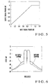
- a power amplifier designed to have good linearity up to a very high amplitude has a large circuit size, and hence increases in cost and power consumption. For this reason, as a transmission power amplifier for a CDMA communication apparatus, a nonlinear compensation amplifier is used, which exhibits good linearity with respect to small amplitude components and nonlinearity with respect to large amplitude components. As shown in Fig. 5, the linearity of this nonlinear compensation amplifier has the input/output characteristics that linearity is maintained up to its maximum output, and when an input amplitude exceeds a value corresponding to the maximum output, the output level becomes constant.
- the simplest method of limiting the input amplitude of the transmission power amplifier is to clip an input signal with a predetermined value. If, however, an input signal is simply clipped, the nonlinear distortion of a signal waveform increases. As a result, the transmission spectrum further spreads, as indicated by the spectrum waveform obtained by "SIMPLE CLIPPING" in Fig. 6. As shown in Fig. 7, therefore, an amplitude limiting circuit is generally provided before a band limiting filter.
- An amplitude limiting circuit 20 shown in Fig. 7 includes an amplitude converter 21 which calculates the amplitude value of an input signal constituted by an in-phase component I and quadrature component Q, a determination unit 22 which compares the amplitude value calculated by the amplitude converter 21 with a preset threshold to output a control value for limiting the amplitude of an input signal that exceeds the threshold, and a clipping circuit 23 which limits an output amplitude to a value equal to or less than the threshold in accordance with the control value output from the determination unit 22.
- the amplitude limiting circuit shown in Fig. 7 is applied to a CDMA communication apparatus of a so-called multicarrier amplification scheme of combining a plurality of carrier signals, shown in Fig. 8, the amplitude of the signal is increased again by processing after amplitude limitation.
- the CDMA communication apparatus shown in Fig. 8 includes a plurality of amplitude limiting circuits 31 1 to 31 N (N is a positive integer) which limit the amplitudes of input signals and a plurality of filters 32 1 to 32 N which pass only predetermined band components.
- the CDMA communication apparatus also includes first frequency converters 33 1 to 33 N which convert input signals as baseband signals into signals having different frequencies for the respective channels, and a carrier combining unit 34 which combines output signals from the first frequency converters 33 1 to 33 N .
- the CDMA communication apparatus further includes a D/A converter 35 which converts the signal obtained by carrier combining into an analog signal, a second frequency converter 36 which converts the output signal from the D/A converter 35 into an RF signal, and a transmission power amplifier 37 which amplifies the RF signal to power necessary for transmission.
- a D/A converter 35 which converts the signal obtained by carrier combining into an analog signal
- a second frequency converter 36 which converts the output signal from the D/A converter 35 into an RF signal
- a transmission power amplifier 37 which amplifies the RF signal to power necessary for transmission.
- the CDMA communication apparatus includes the amplitude limiting circuits 31 1 to 31 N , filters 32 1 to 32 N , and first frequency converters 33 1 to 33 N for the respective channels.
- the present invention has been made to solve the above problems in the prior art, and has as its object to provide an amplitude limiting circuit which can be effectively used to limit an input to a transmission power amplifier incorporated in a CDMA communication apparatus.
- an amplitude limiting circuit for limiting an amplitude of a signal input to a power amplifier, comprising an amplitude converter which calculates an amplitude value of an input signal, a determination unit which detects, as a detection interval, an interval in which the amplitude value exceeds a threshold, on the basis of a preset threshold and the amplitude value of the input signal, a peak detector which detects, in the detection interval, a peak time when a maximum amplitude value appears and an amplitude value at the peak time as a peak value, a window filter which generates a window function for limiting the amplitude value to a value not more than the threshold by using the peak value output from the peak detector, a delay circuit which delays the input signal such that the peak time output from the peak detector coincides with time when the window function output from the window filter exhibits a minimum value, and a multiplier which multiplies an output signal from the delay circuit by the window function.
- an amplitude limiting circuit includes an amplitude converter 1 which calculates the amplitude value of an input signal constituted by an in-phase component I and quadrature component Q and a determination unit 2 which is connected to the amplitude converter 1 and compares a preset threshold with an output value from the amplitude converter to detect an interval in which the amplitude value of the input signal exceeds the threshold.
- the amplitude limiting circuit also includes a peak detector 3 which is connected to the determination unit 2 and detects, in the interval in which the amplitude value of the input signal exceeds the threshold, the time (peak time) when the maximum amplitude value appears and the maximum value (peak value), and a window filter 4 which is connected to the peak detector 3 and generates a predetermined window function by using the values detected by the peak detector 3.
- a peak detector 3 which is connected to the determination unit 2 and detects, in the interval in which the amplitude value of the input signal exceeds the threshold, the time (peak time) when the maximum amplitude value appears and the maximum value (peak value)
- a window filter 4 which is connected to the peak detector 3 and generates a predetermined window function by using the values detected by the peak detector 3.
- the amplitude limiting circuit includes a delay circuit 5 which delays the input signal by a predetermined delay amount and a multiplier 6 which is connected to the delay circuit 5 and multiplies an output signal from the delay circuit 5 by the window function generated by the window filter 4.
- the input signal to the amplitude limiting circuit is a signal which is constituted by the in-phase component I and quadrature component Q and has undergone filtering processing and carrier combining.
- the determination unit 2 includes an amplitude value comparing section 2a which compares the amplitude value calculated by the amplitude converter 1 with a threshold to determine whether or nor the amplitude value exceeds the threshold, and interval detecting section 2b which detects an interval in which the amplitude value of the input signal exceeds the threshold.
- the threshold is set by a threshold input section 7 in advance to a value equal to or less than an input amplitude at which the output of a transmission power amplifier located after the amplitude limiting circuit is not saturated.
- the peak detector 3 In the interval in which it is determined that the amplitude value of the input signal exceeds the threshold, the peak detector 3 outputs the peak time when the maximum amplitude value appears and the peak value at the peak time.
- the window filter 4 outputs a window function which exhibits a value of 1 before and after a preset correction interval longer than the interval in which the amplitude value of the input signal exceeds the threshold, and makes the value at the center of the correction interval proportional to the reciprocal of the peak value.
- the delay circuit 5 delays the input signal such that the peak time coincides with the center of the correction interval.
- the signal output from the delay circuit 5 is multiplied by the window function output from the window filter 4.
- a CDMA communication apparatus of this embodiment includes a plurality of filters 11 1 to 11 N (N is a positive integer) which pass only predetermined band components, and a plurality of first frequency converters 12 1 to 12 N which are respectively connected to the filters 11 1 to 11 N and convert baseband signals passing through the filters into signals with different frequencies for the respective channels.
- the CDMA communication apparatus also includes a carrier combining unit 13 which is connected to the first frequency converters 12 1 to 12 N and combines output signals from the first frequency converters 12 1 to 12 N , and an amplitude limiting circuit 14 which is connected to the carrier combining unit 13 and limits the amplitude of the signal obtained by carrier combining.
- the CDMA communication apparatus includes a D/A converter 15 which is connected to the amplitude limiting circuit 14 and converts the amplitude-limited signal into an analog signal, a second frequency converter 16 which is connected to the D/A converter 15 and converts an output signal from the D/A converter 15 into an RF signal, and a transmission power amplifier 17 which is connected to the second frequency converter 16 and amplifies the RF signal to power necessary for transmission.
- a D/A converter 15 which is connected to the amplitude limiting circuit 14 and converts the amplitude-limited signal into an analog signal
- a second frequency converter 16 which is connected to the D/A converter 15 and converts an output signal from the D/A converter 15 into an RF signal
- a transmission power amplifier 17 which is connected to the second frequency converter 16 and amplifies the RF signal to power necessary for transmission.
- the CDMA communication apparatus includes a filter 11 and first frequency converter 12 for each channel.
- the amplitude converter 1 converts an input signal into an amplitude value
- the determination unit 2 compares the amplitude value with a preset threshold. If the amplitude value exceeds the threshold, the peak detector 3 detects the peak time when the maximum amplitude appears and the peak value at the time.
- ⁇ is set in advance to a value half a value corresponding to a time longer than the interval in which the input signal exceeds the threshold. For example, a value about 10 to 20 times the chip period is used.
- chip rate the unit of time on the abscissa
- the unit of time on the abscissa is represented by "CHIP", which indicates that a given time corresponds to a specific multiple of the chip rate.
- the input signal is delayed by the time ⁇ by the delay circuit 5 (see “DELAY CIRCUIT OUTPUT” in Fig. 3).
- This signal is then multiplied by the window function generated by the window filter 4, and the resultant signal is output (see "OUTPUT SIGNAL” in Fig. 3).
- the multiplier 6 outputs a signal which is wave-shaped such that the peak value is equal to or less than the threshold.
- the window filter 4 generates, for example, a window function w(t) represented by
- this apparatus is free from nonlinear distortion which is caused when a transmission output from the transmission power amplifier 17 on the output stage is saturated, and hence spreading of a transmission spectrum is suppressed. This makes it possible to suppress adjacent channel leakage power.
- the amplitude limiting circuit of this embodiment smoothly limits the amplitude of an input signal by using a window function instead of simply clipping the input signal. This prevents the occurrence of nonlinear distortion due to amplitude limitation processing, and hence suppresses spreading of a transmission spectrum as indicated by the waveform based on "SCHEME ACCORDING PRESENT INVENTION".
- the present invention is configured in the above manner, and hence has the following effects.
- An amplitude limiting circuit includes an amplitude converter which calculates the amplitude value of an input signal, and a determination unit which compares a preset threshold with the amplitude value of the input signal to detect an interval in which the amplitude value exceeds the threshold.
- the amplitude limiting circuit also includes a peak detector which detects, in the interval in which the amplitude value of the input signal exceeds the threshold, the peak time when the amplitude value of the input signal becomes maximum and the amplitude value at the peak time, and a window filter which generates a window function for limiting the amplitude value of the input signal to a value equal to or less than the threshold by using the peak value.
- the amplitude limiting circuit further includes a delay circuit which delays the input signal such that the peak time coincides with the time when the window function exhibits the minimum value, and a multiplier which multiplies an output signal from the delay circuit by the window function.
- the amplitude of the input signal is limited to a value equal to or less than the threshold by using the window function, and hence no nonlinear distortion is caused by amplitude limitation processing. This makes it possible to suppress spreading of the transmission spectrum.
- a CDMA communication apparatus includes a plurality of filters which pass predetermined band components containing input signals, and a plurality of first frequency converters which convert the signals passing through the filters into signals with different frequencies for the respective channels.
- the CDMA communication apparatus also includes a carrier combining unit which combines output signals from the first frequency converters, the above amplitude limiting circuit which limits the amplitude of an output signal from the carrier combining unit, and a D/A converter which converts an output signal from the amplitude limiting circuit into an analog signal.
- the CDMA communication apparatus further includes a second frequency converter which converts the analog signal into an RF signal, and a transmission power amplifier which amplifies the RF signal to power necessary for transmission.
- the amplitude of an output signal from the carrier combining unit is limited by the above amplitude limiting circuit to perform amplitude limitation with respect to the signal obtained by filtering by the baseband filters and carrier combining. This prevents the signal amplitude from increasing again due to processing after amplitude limitation as in the prior art.
- this apparatus is free from nonlinear distortion which is caused when a transmission output from the transmission power amplifier on the transmitting side is saturated, and hence spreading of a transmission spectrum is suppressed. This makes it possible to suppress adjacent channel leakage power.
Abstract
Description
- The present invention relates to an amplitude limiting circuit and, more particularly, to an amplitude limiting circuit which can be suitably used to limit an input to a transmission power amplifier incorporated in a CDMA communication apparatus.
- Recent digital mobile communication systems often use CDMA (Code Division Multiple Access) communication apparatuses to improve the interference resistance ability between communication channels.
- In a CDMA communication apparatus, since the instantaneous power at the time of transmission is much higher than the average power, the linearity of a transmission power amplifier must be maintained up to a very high output level to suppress spreading of a transmission spectrum due to nonlinear distortion so as to reduce adjacent channel leakage power.
- A power amplifier designed to have good linearity up to a very high amplitude has a large circuit size, and hence increases in cost and power consumption. For this reason, as a transmission power amplifier for a CDMA communication apparatus, a nonlinear compensation amplifier is used, which exhibits good linearity with respect to small amplitude components and nonlinearity with respect to large amplitude components. As shown in Fig. 5, the linearity of this nonlinear compensation amplifier has the input/output characteristics that linearity is maintained up to its maximum output, and when an input amplitude exceeds a value corresponding to the maximum output, the output level becomes constant.
- In a transmission power amplifier having input/output characteristics like those shown in Fig. 5, when a signal corresponding to a level exceeding the maximum output is input, a transmission output is saturated to increase nonlinear distortion. As a consequence, the transmission spectrum spreads to increase adjacent channel leakage power, as indicated by the spectrum waveform without "CLIPPING" in Fig. 6.
- It is therefore desirable to maximize the saturation power (maximum output) of the transmission power amplifier. In this case, however, as described above, the circuit size increases to increase power consumption and cost. For this reason, it is important in the CDMA communication apparatus that the instantaneous maximum power of an input signal is limited so as not to exceed the saturation power of the transmission power amplifier.
- The simplest method of limiting the input amplitude of the transmission power amplifier is to clip an input signal with a predetermined value. If, however, an input signal is simply clipped, the nonlinear distortion of a signal waveform increases. As a result, the transmission spectrum further spreads, as indicated by the spectrum waveform obtained by "SIMPLE CLIPPING" in Fig. 6. As shown in Fig. 7, therefore, an amplitude limiting circuit is generally provided before a band limiting filter.
- An
amplitude limiting circuit 20 shown in Fig. 7 includes anamplitude converter 21 which calculates the amplitude value of an input signal constituted by an in-phase component I and quadrature component Q, adetermination unit 22 which compares the amplitude value calculated by theamplitude converter 21 with a preset threshold to output a control value for limiting the amplitude of an input signal that exceeds the threshold, and aclipping circuit 23 which limits an output amplitude to a value equal to or less than the threshold in accordance with the control value output from thedetermination unit 22. - Of an output signal from the
amplitude limiting circuit 20, only a predetermined baseband component is output from afilter 24. In this arrangement, since the frequency component of an output signal is limited by thefilter 24 within a predetermined band, the transmission spectrum does not spread. - In the arrangement shown in Fig. 7, however, since the amplitude limiting circuit and
filter 24 differ in their sampling rates for signal processing, level variations occur at the time of sampling. As a result, the amplitude of the signal passing through thefilter 24 may increase again. - In addition, when the amplitude limiting circuit shown in Fig. 7 is applied to a CDMA communication apparatus of a so-called multicarrier amplification scheme of combining a plurality of carrier signals, shown in Fig. 8, the amplitude of the signal is increased again by processing after amplitude limitation.
- The CDMA communication apparatus shown in Fig. 8 includes a plurality of amplitude limiting circuits 311 to 31N (N is a positive integer) which limit the amplitudes of input signals and a plurality of filters 321 to 32N which pass only predetermined band components.
- The CDMA communication apparatus also includes first frequency converters 331 to 33N which convert input signals as baseband signals into signals having different frequencies for the respective channels, and a
carrier combining unit 34 which combines output signals from the first frequency converters 331 to 33N. - The CDMA communication apparatus further includes a D/
A converter 35 which converts the signal obtained by carrier combining into an analog signal, asecond frequency converter 36 which converts the output signal from the D/A converter 35 into an RF signal, and atransmission power amplifier 37 which amplifies the RF signal to power necessary for transmission. - The CDMA communication apparatus includes the amplitude limiting circuits 311 to 31N, filters 321 to 32N, and first frequency converters 331 to 33N for the respective channels.
- In this arrangement, since signals corresponding to a plurality of channels are subjected to vector combining in the
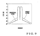
carrier combining unit 34 after amplitude limitation, the effect of the amplitude limitation is lost. As a consequence, the transmission spectrum spreads, as indicated by the spectrum waveform of "CONVENTIONAL SCHEME" in Fig. 9. - The present invention has been made to solve the above problems in the prior art, and has as its object to provide an amplitude limiting circuit which can be effectively used to limit an input to a transmission power amplifier incorporated in a CDMA communication apparatus.
- In order to achieve the above object, according to the present invention, there is provided an amplitude limiting circuit for limiting an amplitude of a signal input to a power amplifier, comprising an amplitude converter which calculates an amplitude value of an input signal, a determination unit which detects, as a detection interval, an interval in which the amplitude value exceeds a threshold, on the basis of a preset threshold and the amplitude value of the input signal, a peak detector which detects, in the detection interval, a peak time when a maximum amplitude value appears and an amplitude value at the peak time as a peak value, a window filter which generates a window function for limiting the amplitude value to a value not more than the threshold by using the peak value output from the peak detector, a delay circuit which delays the input signal such that the peak time output from the peak detector coincides with time when the window function output from the window filter exhibits a minimum value, and a multiplier which multiplies an output signal from the delay circuit by the window function.
- The present invention will be described next with reference to the accompanying drawings.
- Fig. 1 is a block diagram showing an example of the arrangement of an amplitude limiting circuit according to the present invention;
- Fig. 2 is a block diagram showing an example of the arrangement of a CDMA communication apparatus having the amplitude limiting circuit shown in Fig. 1;
- Fig. 3 is a signal waveform chart showing the operation of the amplitude limiting circuit shown in Fig. 1;
- Fig. 4 is a graph showing the transmission spectrum of a signal processed by the amplitude limiting circuit shown in Fig. 1;
- Fig. 5 is a graph showing the input/output characteristics of a transmission power amplifier incorporated in the CDMA communication apparatus;
- Fig. 6 is a graph showing the transmission spectra respectively obtained without clipping an input signal to the transmission power amplifier having the input/output characteristics shown in Fig. 5 and by simply clipping the input signal;
- Fig. 7 is a block diagram showing the arrangement of a conventional amplitude limiting circuit;
- Fig. 8 is a block diagram showing the arrangement of a CDMA communication apparatus including the amplitude limiting circuit shown in Fig. 7; and
- Fig. 9 is a graph showing a transmission spectrum from the CDMA communication apparatus shown in Fig. 8.
-
- As shown in Fig. 1, an amplitude limiting circuit according to the present invention includes an
amplitude converter 1 which calculates the amplitude value of an input signal constituted by an in-phase component I and quadrature component Q and adetermination unit 2 which is connected to theamplitude converter 1 and compares a preset threshold with an output value from the amplitude converter to detect an interval in which the amplitude value of the input signal exceeds the threshold. - The amplitude limiting circuit also includes a
peak detector 3 which is connected to thedetermination unit 2 and detects, in the interval in which the amplitude value of the input signal exceeds the threshold, the time (peak time) when the maximum amplitude value appears and the maximum value (peak value), and awindow filter 4 which is connected to thepeak detector 3 and generates a predetermined window function by using the values detected by thepeak detector 3. - In addition, the amplitude limiting circuit includes a
delay circuit 5 which delays the input signal by a predetermined delay amount and amultiplier 6 which is connected to thedelay circuit 5 and multiplies an output signal from thedelay circuit 5 by the window function generated by thewindow filter 4. - As shown in Fig. 1, the input signal to the amplitude limiting circuit is a signal which is constituted by the in-phase component I and quadrature component Q and has undergone filtering processing and carrier combining.
- The
amplitude converter 1 calculates an amplitude value P of the input signal from the in-phase component I and quadrature component Q by - The
determination unit 2 includes an amplitudevalue comparing section 2a which compares the amplitude value calculated by theamplitude converter 1 with a threshold to determine whether or nor the amplitude value exceeds the threshold, andinterval detecting section 2b which detects an interval in which the amplitude value of the input signal exceeds the threshold. - Note that the threshold is set by a
threshold input section 7 in advance to a value equal to or less than an input amplitude at which the output of a transmission power amplifier located after the amplitude limiting circuit is not saturated. - In the interval in which it is determined that the amplitude value of the input signal exceeds the threshold, the
peak detector 3 outputs the peak time when the maximum amplitude value appears and the peak value at the peak time. - The
window filter 4 outputs a window function which exhibits a value of 1 before and after a preset correction interval longer than the interval in which the amplitude value of the input signal exceeds the threshold, and makes the value at the center of the correction interval proportional to the reciprocal of the peak value. - The
delay circuit 5 delays the input signal such that the peak time coincides with the center of the correction interval. The signal output from thedelay circuit 5 is multiplied by the window function output from thewindow filter 4. - As shown in Fig. 2, a CDMA communication apparatus of this embodiment includes a plurality of filters 111 to 11N (N is a positive integer) which pass only predetermined band components, and a plurality of
first frequency converters 121 to 12N which are respectively connected to the filters 111 to 11N and convert baseband signals passing through the filters into signals with different frequencies for the respective channels. - The CDMA communication apparatus also includes a
carrier combining unit 13 which is connected to thefirst frequency converters 121 to 12N and combines output signals from thefirst frequency converters 121 to 12N, and anamplitude limiting circuit 14 which is connected to thecarrier combining unit 13 and limits the amplitude of the signal obtained by carrier combining. - In addition, the CDMA communication apparatus includes a D/
A converter 15 which is connected to theamplitude limiting circuit 14 and converts the amplitude-limited signal into an analog signal, asecond frequency converter 16 which is connected to the D/A converter 15 and converts an output signal from the D/A converter 15 into an RF signal, and atransmission power amplifier 17 which is connected to thesecond frequency converter 16 and amplifies the RF signal to power necessary for transmission. - That is, the CDMA communication apparatus includes a filter 11 and
first frequency converter 12 for each channel. - In this arrangement, since amplitude limitation is performed with respect to the signal obtained by filtering by the filters 111 to 11N and carrier combining, there is no chance that the signal amplitude increases again by processing after amplitude limitation as in the prior art.
- The operation of the amplitude limiting circuit according to the present invention will be described next with reference to Figs. 3 and 4.
- In the amplitude limiting circuit of this embodiment, the
amplitude converter 1 converts an input signal into an amplitude value, and thedetermination unit 2 compares the amplitude value with a preset threshold. If the amplitude value exceeds the threshold, thepeak detector 3 detects the peak time when the maximum amplitude appears and the peak value at the time. - The
window filter 4 generates a function exhibiting a value which is 1 until the peak value, gradually decreases thereafter to become A (= threshold/peak value) after a lapse of a time τ, and gradually increases thereafter to return to 1 after a lapse of the time τ (see "WINDOW FUNCTION" in Fig. 3). - In this case, τ is set in advance to a value half a value corresponding to a time longer than the interval in which the input signal exceeds the threshold. For example, a value about 10 to 20 times the chip period is used.
- Note that the chip period is the reciprocal of the spreading frequency (= chip rate) used in the CDMA communication apparatus. Referring to Fig. 3, the unit of time on the abscissa is represented by "CHIP", which indicates that a given time corresponds to a specific multiple of the chip rate.
- The input signal is delayed by the time τ by the delay circuit 5 (see "DELAY CIRCUIT OUTPUT" in Fig. 3). This signal is then multiplied by the window function generated by the
window filter 4, and the resultant signal is output (see "OUTPUT SIGNAL" in Fig. 3). At this time, themultiplier 6 outputs a signal which is wave-shaped such that the peak value is equal to or less than the threshold. - The
window filter 4 generates, for example, a window function w(t) represented by
- In this case, when t = τ, it suffices if w(t) = 1 - 2a ≦ A. For example, a = (1 - A)/2 is set.
- As shown in Fig. 2, in the CDMA communication apparatus of this embodiment, since amplitude limitation is performed with respect to the signal obtained by filtering by the filters and carrier combining, there is no chance that the signal amplitude increases again by processing after amplitude limitation as in the prior art.
- Therefore, this apparatus is free from nonlinear distortion which is caused when a transmission output from the
transmission power amplifier 17 on the output stage is saturated, and hence spreading of a transmission spectrum is suppressed. This makes it possible to suppress adjacent channel leakage power. - The amplitude limiting circuit of this embodiment smoothly limits the amplitude of an input signal by using a window function instead of simply clipping the input signal. This prevents the occurrence of nonlinear distortion due to amplitude limitation processing, and hence suppresses spreading of a transmission spectrum as indicated by the waveform based on "SCHEME ACCORDING PRESENT INVENTION".
- The present invention is configured in the above manner, and hence has the following effects.
- An amplitude limiting circuit according to the present invention includes an amplitude converter which calculates the amplitude value of an input signal, and a determination unit which compares a preset threshold with the amplitude value of the input signal to detect an interval in which the amplitude value exceeds the threshold.
- The amplitude limiting circuit also includes a peak detector which detects, in the interval in which the amplitude value of the input signal exceeds the threshold, the peak time when the amplitude value of the input signal becomes maximum and the amplitude value at the peak time, and a window filter which generates a window function for limiting the amplitude value of the input signal to a value equal to or less than the threshold by using the peak value.
- The amplitude limiting circuit further includes a delay circuit which delays the input signal such that the peak time coincides with the time when the window function exhibits the minimum value, and a multiplier which multiplies an output signal from the delay circuit by the window function.
- With this operation, the amplitude of the input signal is limited to a value equal to or less than the threshold by using the window function, and hence no nonlinear distortion is caused by amplitude limitation processing. This makes it possible to suppress spreading of the transmission spectrum.
- A CDMA communication apparatus according to the present invention includes a plurality of filters which pass predetermined band components containing input signals, and a plurality of first frequency converters which convert the signals passing through the filters into signals with different frequencies for the respective channels.
- The CDMA communication apparatus also includes a carrier combining unit which combines output signals from the first frequency converters, the above amplitude limiting circuit which limits the amplitude of an output signal from the carrier combining unit, and a D/A converter which converts an output signal from the amplitude limiting circuit into an analog signal.
- The CDMA communication apparatus further includes a second frequency converter which converts the analog signal into an RF signal, and a transmission power amplifier which amplifies the RF signal to power necessary for transmission.
- With this operation, the amplitude of an output signal from the carrier combining unit is limited by the above amplitude limiting circuit to perform amplitude limitation with respect to the signal obtained by filtering by the baseband filters and carrier combining. This prevents the signal amplitude from increasing again due to processing after amplitude limitation as in the prior art.
- Therefore, this apparatus is free from nonlinear distortion which is caused when a transmission output from the transmission power amplifier on the transmitting side is saturated, and hence spreading of a transmission spectrum is suppressed. This makes it possible to suppress adjacent channel leakage power.
Claims (8)
- An amplitude limiting circuit for limiting an amplitude of a signal input to a power amplifier, characterized by comprising:an amplitude converter (1) which calculates an amplitude value of an input signal;a determination unit (2) which detects, as a detection interval, an interval in which the amplitude value exceeds a threshold, on the basis of a preset threshold and the amplitude value of the input signal;a peak detector (3) which detects, in the detection interval, peak time when a maximum amplitude value appears and an amplitude value at the peak time as a peak value;a window filter (4) which generates a window function for limiting the amplitude value to a value not more than the threshold by using the peak value output from said peak detector (3);a delay circuit (5) which delays the input signal such that the peak time output from said peak detector (3) coincides with time when the window function output from said window filter (4) exhibits a minimum value; anda multiplier (6) which multiplies an output signal from said delay circuit (5) by the window function.
- A circuit according to claim 1, wherein said determination unit (2) comprises
an amplitude comparing section (2a) which compares the preset threshold with the amplitude value of the input signal, and
an interval detecting section (2b) which detects an interval in which the amplitude value exceeds the threshold. - A circuit according to claim 1 or 2, wherein
said window filter (4) outputs a window function which exhibits a value of 1 before and after a preset correction interval longer than the detection interval and makes a value at the center of the correction interval proportional to the reciprocal of the peak value, and
said delay circuit (5) delays the input signal such that the peak time coincides with the center of the correction interval. - A circuit according to claim 3, wherein said window filter (4) outputs a window function exhibiting a value which is 1 until the peak value and becomes not more than a value (threshold/peak value) at the center of the correction interval after the peak time.
- A circuit according to claim 3 or 4, wherein
letting threshold/peak value A, a = (1 - A)/2, and τ be a value 1/2 a preset correction interval, said window filter (4) outputs a window function w(t) represented byand
said delay circuit (5) delays the input signal by the time τ. - A circuit according to claim 1, 2, 3, 4 or 5, further comprising a threshold input section (7) which inputs a threshold to said determination unit (2).
- A CDMA communication apparatus characterized by comprising:a plurality of filters (111 - 11N) (N is a positive integer) which pass predetermined band components containing input signals;a plurality of first frequency converters (121 - 12N) which convert the signals passing through said filters (111 - 11N) into signals with different frequencies for the respective channels;a carrier combining unit (13) which combines the output signals from said first frequency converters (121 - 12N);an amplitude limiting circuit (14) which limits an amplitude of an output signal from said carrier combining unit (13);a D/A converter (15) which converts an output signal from said amplitude limiting circuit (14) into an analog signal;a second frequency converter (16) which converts the analog signal into an RF signal; anda transmission power amplifier (17) which amplifies the RF signal to power necessary for transmission.
- An apparatus according to claim 7, wherein said amplitude limiting circuit (14) comprises
an amplitude converter (1) which calculates an amplitude value of an input signal,
a determination unit (2) which detects, as a detection interval, an interval in which the amplitude value exceeds a threshold, on the basis of a preset threshold and the amplitude value of the input signal,
a peak detector (3) which detects, in the detection interval, peak time when a maximum amplitude value appears and an amplitude value at the peak time as a peak value,
a window filter (4) which generates a window function for limiting the amplitude value to a value not more than the threshold by using the peak value output from said peak detector (3),
a delay circuit (5) which delays the input signal such that the peak time output from said peak detector (3) coincides with time when the window function output from said window filter (4) exhibits a minimum value, and
a multiplier (6) which multiplies an output signal from said delay circuit (5) by the window function.
Priority Applications (1)
| Application Number | Priority Date | Filing Date | Title |
|---|---|---|---|
| EP20060009059 EP1696577A3 (en) | 2002-08-22 | 2003-08-20 | Amplitude limiting circuit and CDMA communication apparatus |
Applications Claiming Priority (2)
| Application Number | Priority Date | Filing Date | Title |
|---|---|---|---|
| JP2002241830A JP4288458B2 (en) | 2002-08-22 | 2002-08-22 | Amplitude limiting circuit and CDMA communication apparatus |
| JP2002241830 | 2002-08-22 |
Related Child Applications (1)
| Application Number | Title | Priority Date | Filing Date |
|---|---|---|---|
| EP20060009059 Division EP1696577A3 (en) | 2002-08-22 | 2003-08-20 | Amplitude limiting circuit and CDMA communication apparatus |
Publications (2)
| Publication Number | Publication Date |
|---|---|
| EP1391996A2 true EP1391996A2 (en) | 2004-02-25 |
| EP1391996A3 EP1391996A3 (en) | 2005-11-23 |
Family
ID=31185217
Family Applications (2)
| Application Number | Title | Priority Date | Filing Date |
|---|---|---|---|
| EP20060009059 Withdrawn EP1696577A3 (en) | 2002-08-22 | 2003-08-20 | Amplitude limiting circuit and CDMA communication apparatus |
| EP20030018650 Withdrawn EP1391996A3 (en) | 2002-08-22 | 2003-08-20 | Amplitude limiting circuit and CDMA communication apparatus |
Family Applications Before (1)
| Application Number | Title | Priority Date | Filing Date |
|---|---|---|---|
| EP20060009059 Withdrawn EP1696577A3 (en) | 2002-08-22 | 2003-08-20 | Amplitude limiting circuit and CDMA communication apparatus |
Country Status (5)
| Country | Link |
|---|---|
| US (1) | US7369580B2 (en) |
| EP (2) | EP1696577A3 (en) |
| JP (1) | JP4288458B2 (en) |
| CN (1) | CN1232064C (en) |
| HK (1) | HK1064533A1 (en) |
Cited By (1)
| Publication number | Priority date | Publication date | Assignee | Title |
|---|---|---|---|---|
| WO2007036978A1 (en) | 2005-09-27 | 2007-04-05 | Fujitsu Limited | Radio transmission device having peak suppression function |
Families Citing this family (7)
| Publication number | Priority date | Publication date | Assignee | Title |
|---|---|---|---|---|
| WO2006103924A1 (en) * | 2005-03-25 | 2006-10-05 | Matsushita Electric Industrial Co., Ltd. | Peak power reducing device and peak power reducing method |
| JP2007089029A (en) * | 2005-09-26 | 2007-04-05 | Nippon Hoso Kyokai <Nhk> | Acoustic signal compression apparatus and acoustic signal compression program |
| JP4750592B2 (en) * | 2006-03-17 | 2011-08-17 | 富士通株式会社 | Peak suppression method, peak suppression device, and wireless transmission device |
| US7796193B2 (en) * | 2006-06-29 | 2010-09-14 | Mediatek Inc. | Method of adaptive slicing signal |
| JP5170259B2 (en) | 2008-12-22 | 2013-03-27 | 日本電気株式会社 | Distortion compensation circuit, transmitter, and distortion compensation method |
| US9001678B2 (en) * | 2012-02-29 | 2015-04-07 | Hong Kong Applied Science And Technology Research Institute Co., Ltd. | False alarm reduction with search windowing and peak suppression |
| CN112532208B (en) * | 2019-09-18 | 2024-04-05 | 惠州迪芬尼声学科技股份有限公司 | Harmonic generator and method for generating harmonics |
Citations (7)
| Publication number | Priority date | Publication date | Assignee | Title |
|---|---|---|---|---|
| US5287387A (en) * | 1992-03-06 | 1994-02-15 | Motorola, Inc. | Low splatter peak-to-average signal reduction |
| EP0743768A1 (en) * | 1994-12-05 | 1996-11-20 | Ntt Mobile Communications Network Inc. | Device and method for multiplexing signal |
| EP0751630A2 (en) * | 1995-06-30 | 1997-01-02 | Nec Corporation | Code division multiple access base station transmitter |
| US5638403A (en) * | 1995-04-28 | 1997-06-10 | Motorola, Inc. | Low-splatter peak-to-average signal reduction with interpolation |
| US5710990A (en) * | 1996-03-21 | 1998-01-20 | Motorola, Inc. | Transmitter which adjusts peak-to-average power of a multicarrier signal by switching between a group of channels and a phase-adjusted group of channels |
| US5742900A (en) * | 1994-09-30 | 1998-04-21 | Comsat Corporation | Voltage-variable biased inverting limiter for RFI suppression overview |
| US6434135B1 (en) * | 1999-08-31 | 2002-08-13 | Interdigital Technology Corporation | Adaptive RF amplifier prelimiter |
Family Cites Families (10)
| Publication number | Priority date | Publication date | Assignee | Title |
|---|---|---|---|---|
| JP3335777B2 (en) | 1994-09-05 | 2002-10-21 | 松下通信工業株式会社 | Spread spectrum communication equipment |
| JPH10111354A (en) | 1996-10-04 | 1998-04-28 | Toshiba Corp | High-frequency amplifier |
| JP3548657B2 (en) * | 1996-10-17 | 2004-07-28 | 株式会社日立製作所 | Multiplex signal transmitter |
| US6266320B1 (en) * | 1998-04-08 | 2001-07-24 | Telefonaktiebolaget Lm Ericsson (Publ) | Amplitude limitation in CDMA system |
| DE19824233B4 (en) * | 1998-05-29 | 2005-10-06 | Telefonaktiebolaget Lm Ericsson (Publ) | amplitude limiting |
| US6236864B1 (en) * | 1998-11-27 | 2001-05-22 | Nortel Networks Limited | CDMA transmit peak power reduction |
| JP2001285088A (en) | 2000-03-31 | 2001-10-12 | Oki Electric Ind Co Ltd | Transmitter |
| US7170952B2 (en) * | 2001-07-02 | 2007-01-30 | Powerwave Technologies, Inc. | System and method for post filtering peak power reduction in communications systems |
| US6931239B2 (en) * | 2001-07-30 | 2005-08-16 | Hitachi Kokusai Electric Inc. | Peak limiter and multi-carrier amplification apparatus |
| US7095798B2 (en) * | 2001-08-02 | 2006-08-22 | Powerwave Technologies, Inc. | System and method for post filtering peak power reduction in multi-carrier communications systems |
-
2002
- 2002-08-22 JP JP2002241830A patent/JP4288458B2/en not_active Expired - Fee Related
-
2003
- 2003-08-19 US US10/642,614 patent/US7369580B2/en not_active Expired - Fee Related
- 2003-08-20 EP EP20060009059 patent/EP1696577A3/en not_active Withdrawn
- 2003-08-20 EP EP20030018650 patent/EP1391996A3/en not_active Withdrawn
- 2003-08-22 CN CNB031539696A patent/CN1232064C/en not_active Expired - Fee Related
-
2004
- 2004-09-17 HK HK04107171A patent/HK1064533A1/en not_active IP Right Cessation
Patent Citations (7)
| Publication number | Priority date | Publication date | Assignee | Title |
|---|---|---|---|---|
| US5287387A (en) * | 1992-03-06 | 1994-02-15 | Motorola, Inc. | Low splatter peak-to-average signal reduction |
| US5742900A (en) * | 1994-09-30 | 1998-04-21 | Comsat Corporation | Voltage-variable biased inverting limiter for RFI suppression overview |
| EP0743768A1 (en) * | 1994-12-05 | 1996-11-20 | Ntt Mobile Communications Network Inc. | Device and method for multiplexing signal |
| US5638403A (en) * | 1995-04-28 | 1997-06-10 | Motorola, Inc. | Low-splatter peak-to-average signal reduction with interpolation |
| EP0751630A2 (en) * | 1995-06-30 | 1997-01-02 | Nec Corporation | Code division multiple access base station transmitter |
| US5710990A (en) * | 1996-03-21 | 1998-01-20 | Motorola, Inc. | Transmitter which adjusts peak-to-average power of a multicarrier signal by switching between a group of channels and a phase-adjusted group of channels |
| US6434135B1 (en) * | 1999-08-31 | 2002-08-13 | Interdigital Technology Corporation | Adaptive RF amplifier prelimiter |
Non-Patent Citations (3)
| Title |
|---|
| PATENT ABSTRACTS OF JAPAN vol. 1996, no. 07, 31 July 1996 (1996-07-31) & JP 08 079132 A (MATSUSHITA COMMUN IND CO LTD; N T T IDO TSUSHINMO KK), 22 March 1996 (1996-03-22) * |
| PATENT ABSTRACTS OF JAPAN vol. 1998, no. 09, 31 July 1998 (1998-07-31) & JP 10 111354 A (TOSHIBA CORP), 28 April 1998 (1998-04-28) * |
| PATENT ABSTRACTS OF JAPAN vol. 2002, no. 02, 2 April 2002 (2002-04-02) & JP 2001 285088 A (OKI ELECTRIC IND CO LTD), 12 October 2001 (2001-10-12) * |
Cited By (3)
| Publication number | Priority date | Publication date | Assignee | Title |
|---|---|---|---|---|
| WO2007036978A1 (en) | 2005-09-27 | 2007-04-05 | Fujitsu Limited | Radio transmission device having peak suppression function |
| EP1940058A1 (en) * | 2005-09-27 | 2008-07-02 | Fujitsu Ltd. | Radio transmission device having peak suppression function |
| EP1940058A4 (en) * | 2005-09-27 | 2012-01-25 | Fujitsu Ltd | Radio transmission device having peak suppression function |
Also Published As
| Publication number | Publication date |
|---|---|
| JP4288458B2 (en) | 2009-07-01 |
| EP1696577A2 (en) | 2006-08-30 |
| CN1487687A (en) | 2004-04-07 |
| US20040047317A1 (en) | 2004-03-11 |
| JP2004080696A (en) | 2004-03-11 |
| EP1696577A3 (en) | 2008-06-11 |
| US7369580B2 (en) | 2008-05-06 |
| CN1232064C (en) | 2005-12-14 |
| HK1064533A1 (en) | 2005-01-28 |
| EP1391996A3 (en) | 2005-11-23 |
Similar Documents
| Publication | Publication Date | Title |
|---|---|---|
| US6504862B1 (en) | Method and apparatus for reducing the ratio of peak to average power in a Gaussian signal including a CDMA signal | |
| EP1282225B1 (en) | Peak limiter and multi-carrier amplification apparatus | |
| KR100367433B1 (en) | Transmitter | |
| US8140106B2 (en) | Peak factor reduction device and base station | |
| US6144694A (en) | Transmitting apparatus for code division multiplexed signals | |
| KR100605440B1 (en) | Amplitude limitation in a cdma system | |
| EP1396970B1 (en) | Method for scaling signal peaks and corresponding transmitter | |
| US20100158166A1 (en) | Noise Injection Circuit and Method for Signal Processing | |
| US7369580B2 (en) | Amplitude limiting circuit and CDMA communication apparatus | |
| US20050281345A1 (en) | Device and method for reducing peaks of a composite signal | |
| US6515961B1 (en) | Decresting peaks in a CDMA signal | |
| JP3702829B2 (en) | Peak factor reduction device | |
| US20050083996A1 (en) | Systems and methods for signal conversion | |
| US6654427B1 (en) | Signal notching system for limiting signal peaks | |
| JP4737458B2 (en) | Reception amplitude correction circuit, reception amplitude correction method, and receiver using the same | |
| US7123644B2 (en) | Peak cancellation apparatus of base station transmission unit | |
| EP2647130B1 (en) | Receiver gain adjustment to reducing an influence of a dc offset | |
| JP2005057532A (en) | Electric power limiting circuit | |
| EP1569350A1 (en) | Power limit device and digital radio transmitter using the same | |
| JP2003046480A (en) | Peak limiter and multi-carrier amplifier | |
| EP1318612A2 (en) | Nonlinear compensating circuit, base-station apparatus, and transmission power clipping method | |
| EP1405427B1 (en) | System and method for post filtering peak power reduction in communications systems | |
| KR100475180B1 (en) | Diminish appatatus for Peak to Average Ratio in multi-carrier transmitter | |
| JP2000209127A (en) | Spread spectrum communication unit |
Legal Events
| Date | Code | Title | Description |
|---|---|---|---|
| PUAI | Public reference made under article 153(3) epc to a published international application that has entered the european phase |
Free format text: ORIGINAL CODE: 0009012 |
|
| AK | Designated contracting states |
Kind code of ref document: A2 Designated state(s): AT BE BG CH CY CZ DE DK EE ES FI FR GB GR HU IE IT LI LU MC NL PT RO SE SI SK TR |
|
| AX | Request for extension of the european patent |
Extension state: AL LT LV MK |
|
| PUAL | Search report despatched |
Free format text: ORIGINAL CODE: 0009013 |
|
| AK | Designated contracting states |
Kind code of ref document: A3 Designated state(s): AT BE BG CH CY CZ DE DK EE ES FI FR GB GR HU IE IT LI LU MC NL PT RO SE SI SK TR |
|
| AX | Request for extension of the european patent |
Extension state: AL LT LV MK |
|
| 17P | Request for examination filed |
Effective date: 20051021 |
|
| AKX | Designation fees paid |
Designated state(s): DE GB |
|
| 17Q | First examination report despatched |
Effective date: 20060123 |
|
| STAA | Information on the status of an ep patent application or granted ep patent |
Free format text: STATUS: THE APPLICATION IS DEEMED TO BE WITHDRAWN |
|
| 18D | Application deemed to be withdrawn |
Effective date: 20070202 |