EP1453176A2 - Batterieladeschaltung für ein Mobiltelephon und Verfahren für den Betrieb desselben und Ladevorrichtung für ein Mobiltelephone und Lademethode für dasselbe - Google Patents
Batterieladeschaltung für ein Mobiltelephon und Verfahren für den Betrieb desselben und Ladevorrichtung für ein Mobiltelephone und Lademethode für dasselbe Download PDFInfo
- Publication number
- EP1453176A2 EP1453176A2 EP04002430A EP04002430A EP1453176A2 EP 1453176 A2 EP1453176 A2 EP 1453176A2 EP 04002430 A EP04002430 A EP 04002430A EP 04002430 A EP04002430 A EP 04002430A EP 1453176 A2 EP1453176 A2 EP 1453176A2
- Authority
- EP
- European Patent Office
- Prior art keywords
- charger
- mobile phone
- electric double
- layer capacitors
- power source
- Prior art date
- Legal status (The legal status is an assumption and is not a legal conclusion. Google has not performed a legal analysis and makes no representation as to the accuracy of the status listed.)
- Withdrawn
Links
Images


Classifications
-
- H—ELECTRICITY
- H02—GENERATION; CONVERSION OR DISTRIBUTION OF ELECTRIC POWER
- H02J—CIRCUIT ARRANGEMENTS OR SYSTEMS FOR SUPPLYING OR DISTRIBUTING ELECTRIC POWER; SYSTEMS FOR STORING ELECTRIC ENERGY
- H02J7/00—Circuit arrangements for charging or depolarising batteries or for supplying loads from batteries
- H02J7/02—Circuit arrangements for charging or depolarising batteries or for supplying loads from batteries for charging batteries from AC mains by converters
- H02J7/04—Regulation of charging current or voltage
-
- H02J7/731—
-
- H—ELECTRICITY
- H02—GENERATION; CONVERSION OR DISTRIBUTION OF ELECTRIC POWER
- H02J—CIRCUIT ARRANGEMENTS OR SYSTEMS FOR SUPPLYING OR DISTRIBUTING ELECTRIC POWER; SYSTEMS FOR STORING ELECTRIC ENERGY
- H02J7/00—Circuit arrangements for charging or depolarising batteries or for supplying loads from batteries
- H02J7/34—Parallel operation in networks using both storage and other DC sources, e.g. providing buffering
- H02J7/345—Parallel operation in networks using both storage and other DC sources, e.g. providing buffering using capacitors as storage or buffering devices
-
- H02J7/70—
-
- H—ELECTRICITY
- H01—ELECTRIC ELEMENTS
- H01M—PROCESSES OR MEANS, e.g. BATTERIES, FOR THE DIRECT CONVERSION OF CHEMICAL ENERGY INTO ELECTRICAL ENERGY
- H01M10/00—Secondary cells; Manufacture thereof
- H01M10/42—Methods or arrangements for servicing or maintenance of secondary cells or secondary half-cells
- H01M10/44—Methods for charging or discharging
-
- H02J2105/44—
-
- Y—GENERAL TAGGING OF NEW TECHNOLOGICAL DEVELOPMENTS; GENERAL TAGGING OF CROSS-SECTIONAL TECHNOLOGIES SPANNING OVER SEVERAL SECTIONS OF THE IPC; TECHNICAL SUBJECTS COVERED BY FORMER USPC CROSS-REFERENCE ART COLLECTIONS [XRACs] AND DIGESTS
- Y02—TECHNOLOGIES OR APPLICATIONS FOR MITIGATION OR ADAPTATION AGAINST CLIMATE CHANGE
- Y02E—REDUCTION OF GREENHOUSE GAS [GHG] EMISSIONS, RELATED TO ENERGY GENERATION, TRANSMISSION OR DISTRIBUTION
- Y02E60/00—Enabling technologies; Technologies with a potential or indirect contribution to GHG emissions mitigation
- Y02E60/10—Energy storage using batteries
Definitions
- This invention relates to a charger for mobile phone and an operation method for the same, and, a charging apparatus for mobile phone and a charging method for the same.
- any one of the chargers (dischargers) of 1 ⁇ to 5 ⁇ is not appropriate for a mobile phone.
- the conventional charger for mobile phone (refer to the above 1 ⁇ has a great disadvantage that the mobile phone is restricted for a long time until the battery is fully charged because the commercial power is converted to DC voltage for the battery, and the mobile phone is connected to the charger to charge for a certain period of time.
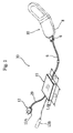
- FIG. 1 is a perspective view showing an embodiment of a charger for mobile phone of the present invention
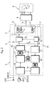
- Figure 2 is a basic explanatory circuit diagram.
- this charger 30 is provided with a power input portion 12, a charging case 15 connected to the power input portion 12 through a cord 29, and an output portion 6 connected to the charging case 15 through a cord 9.
- the power input portion 12 is provided with a plug 12A for a commercial power source 14 and (when desired) a plug 12B for a car battery 13.
- two plugs 12A and 12B may be provided to connect the power input portion 12 alternatively to the commercial power source 14 or the car battery 13.
- the charging case 15 is provided with a switching power source portion 1 supplied with electric power by the power input portion 12, a control portion 2 having a micro-computer logic circuit 25 and supplied with electric energy by the switching power source portion 1, a capacitor portion 3 having plural electric double-layer capacitors (condensers) 4 to accumulate the electric energy supplied by the control portion 2, and a feedback circuit 5 to transmit charging state of the electric double-layer capacitors 4 to the control portion 2.
- the plural electric double-layer capacitors 4 are serially connected.
- the power input portion 12 is (detachably) connected to a power source 7 such as the commercial power source 14 and the car battery 13, and the output portion 6 is (detachably) connected to a battery 8 of a mobile phone 10.
- Electric current I 1 running from the control portion 2 to the electric double-layer capacitors 4 is controlled by the control portion 2 to be much larger than electric current I 2 running from the electric double-layer capacitors 4 to the output portion 6, namely, l 1 >> l 2 .
- l 1 and l 2 are set to be 5 ⁇ l 1 / l 2 ⁇ 50. More preferably, 10 ⁇ l 1 / l 2 ⁇ 25.
- charge and supplied voltage of the electric double-layer capacitors 4 are controlled by the control portion 2 as to correspond to charging state of the electric double-layer capacitors 4 transmitted by the feedback circuit.
- the output portion 6 has a constant current (DC - DC) converter to supply (output) constant current to the battery 8. It is also preferable to include the constant current (DC - DC) converter within the charging case 15.
- a mark 31 represents a detecting portion connected to each of the electric double-layer capacitors 4 to detect terminal voltage V 1 , V 2 , V 3 , etc.
- Each voltage V 1 , V 2 V 3 , etc. detected by the detecting portion 31 is sent to the control portion 2 through the feedback circuit 5.
- Total voltage value is calculated by a program control of the micro-computer logic circuit 25 of the control portion 2 as each of terminal voltage V 1 , V 2 , V 3 , etc. is within an operational range (even if the electric double-layer capacitors 4 are different one another in electrostatic capacity and internal resistance).
- the calculated total voltage is supplied to the serially-connected plural electric double-layer capacitors 4 as supplied voltage E (refer to Figure 3).
- a mark 26 represents a current-voltage control portion for this process.
- the switching power source portion 1 is provided with a rectifier circuit 16 supplied with electric power by the commercial power source 14, a switching portion 17 and an auxiliary power source 19 supplied with electric energy by the rectifier circuit 16, and a high-frequency rectifier circuit 18 supplied with the electric energy by the switching portion 17 through an output transformer 22. Further, the switching power source portion 1 is provided with a constant voltage control portion 21 and a PWM control portion 20 to detect and make constant the voltage of the electric energy supplied to the control portion 2 by the high-frequency rectifier circuit 18, and a driving transformer 23 for transmitting control signals of the PWM control portion 20 to the switching portion 17. And, the high-frequency rectifier circuit 18 is connected to the car battery 13.
- the charging case 15 is, for example, formed to be a rectangular parallelepiped having a longitudinal side L 1 (10 cm to 15cm), a lateral side L 2 (8cm to 10cm), and a thickness L 3 (0.5cm to 3 cm) as to have a magnitude (size) easily held in a handbag, a pocket, or a bag and carried.
- Figure 3 is a circuit diagram of the serially-connected plural electric double-layer capacitors 4 having electrostatic capacity C 1 , C 2 , ..., C n , and V 1 , V 2 , ..., V n indicate terminal voltage as described above.
- E is the above-mentioned supplied voltage of the capacitor portion 3 which corresponds to V 1 + V 2 + V 3 + ... + V n (namely, the total voltage).
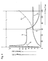
- Figure 4 is a graph in which time T (sec.) is indicated on an axis of abscissa, and current l 1 (A) and the above-mentioned supplied voltage E (V) are indicated on an axis of ordinate.
- t 1 is a period of constant current
- t 2 is a period of constant voltage
- l p indicates a value of intrusion current when the current begins running through the capacitor portion 3.
- the current I without control may rapidly increase as E 2 curve shown with a two-dot broken line and go over the operational voltage of the electric double-layer capacitors 4.
- the control portion 2 controls as the current l 1 is gradually decreased and the supplied (charging) voltage E is constant value E 0 in the period t 2 of constant voltage.
- inconstant change in the voltage E 3 is also controlled by the control portion 2.
- the current I 1 becomes a low value such as 1(A).
- the voltage E 0 is, for example, within a range of 4 to 8 (V).
- the switching power source portion 1 is controlled by the program control of the micro-computer logic circuit 25 of the control portion 2 as each terminal voltage V 1 , V 2 , ..., V n of the plural electric double-layer capacitors 4 is detected and transmitted to the control portion 2 by the feedback circuit 5 to supply the current l 1 of the maximum power of the switching power source portion 1.
- the control in the period t 1 of constant current shown in Figure 4 is conducted as that terminal voltage V 1 , V 2 , ..., V n of the electric double-layer capacitors 4 and the charging current l 1 are detected, and the current l 1 of the maximum power of the switching power source portion 1 and the voltage E(E 0 ) to supply the current l 1 are controlled by the program of the micro-computer logic circuit 25.
- the intrusion current l p may be controlled as the early current l 1 , is regulated under approximately constant current l f not to be over the resistance of the electric double-layer capacitors 4 for safer charging.
- the exhausted battery 8 of the mobile phone 10 can be charged and the mobile phone 10 can be used in connected state when the user is out because the charger 30 for mobile phone of the present invention has a size can be held in bags and pockets, and carried with the charged electric double-layer capacitors 4.
- charging site is not restricted to the installation site of the commercial power source 14, and the charger 30 can be charged in outing by a car because the charger 30 can be charged with not only the commercial power source 14, but the car battery 13 as the power source 7.
- the charger 30 can be charged rapidly (within a range of 30 seconds to 2 minutes) to reduce waiting time in hasty preparation for outing because the current l 1 running toward the electric double-layer capacitors 4 is much larger than the current l 2 running toward the battery 8 of the mobile phone 10 through the output portion 6.
- this compact charger 30 is taken around (carried) with the mobile phone 10 in bags and pockets, the battery 8 can be charged when needed immediately in any place with connection through the cord 9, further, the mobile phone 10 can be used for a long time (when charged while the mobile phone 10 is used in a staying place) because discharge toward the battery 8 of the mobile phone 10 takes a long time.
- the power input portion 12 of the charger 30, provided with the capacitor portion 3 having plural electric double-layer capacitors 4, the power input portion 12, and the output portion 6, is connected to the commercial power source 14 or the car battery 13 to conduct boosting charge of the capacitor portion 3, then, the power input portion 12 is separated to carry the charger 30, the output portion 6 of the carried charger 30 is connected to the battery 8 of the mobile phone 10 to charge with a period of time 5 to 50 times longer than the time of the boosting charge. After the boosting charge at home or in the car, the battery of the mobile phone 10 can be charged slowly.
- the charger 30 can be effectively used without damaging the electric double-layer capacitors 4 because the terminal voltages V 1 , V 2 , ..., V n of the serially-connected electric double-layer capacitors 4 are detected by the detecting portion 31 to control the total voltage E within the preliminarily input voltage (operational voltage) E 0 .
- This charging apparatus for mobile phone is provided with a stationary public charger 66 of box-shape and plural (small) portable chargers 70 held in handbags, baggage, pockets, etc.
- the box-shaped public charger 66 is placed in convenience stores, hotels, stations (for transportation such as trains and buses), and public spaces, and having a coin slot 62 and a jack (terminal) 55 to connect the portable charger 70.
- the stationary public charger 66 is connected to a commercial power source 14 through an input plug (connection terminal portion) 69, and AC 100V is rectified and decreased to, for example, DC 12V, and supplied to a battery 53 through a control portion 52 to be accumulated.
- the battery 53 can be sufficiently large for the stationary public charger 66.
- a mark 54 represents a constant power control portion connected to an output side of the battery 53, and an output side of the constant power control portion 54 is connected to the above-mentioned terminal (jack) 55.
- a sensor switch 64 is disposed in a box B of the stationary public charger 66 to detect feeding of a coin 63 to the coin slot 62.
- Coin detection signal l 64 from the sensor switch 64 is sent to the constant power control portion 54.
- the constant power control portion 54 controls as electric energy is supplied to a capacitor portion 57 of the portable charger 70 in connected state.
- the stationary public charger 66 has an on-off control means 80 to control as to supply the capacitor portion 57 of the portable charger 70 in connected state with the electric energy by detection work of the sensor switch 64.
- the on-off control means 80 is composed of the sensor switch 64, wiring (to transmit the detection signal l 64 ), and the constant power control portion 54.
- the stationary public charger 66 is provided with the power source portion 51 to rectify and decrease the AC power from the commercial power source 14, the battery 53 to accumulate the DC power from the power source portion 51, the control portion 52 to regulate charging amount to the battery 53, the constant power control portion 54 to control as to supply constant power to the portable charger 70 in the connected state, the terminal (jack) 55 to which the portable charger 70 is detachably connected, and the sensor switch 64.
- the public charger 66 has the on-off control means 80 to control as that the electric energy is supplied to the portable charger 70 when the sensor switch 64 works by detection of the feeding of the coin 63.
- a mark 65 represents a charging-state indicator such as an LED lamp, a liquid-crystal indicator, etc., on which switching on and off of the on-off control means 80, and charging state or charging amount of the portable charger 70 by the capacitor portion 57 are indicated.
- a user of the portable charger 70 separates a connecting terminal 56 from the jack (terminal) 55 according to the indicator 65.
- the battery 53 installed in the fixed box B a large battery having large capacity can be used. And, it is preferable to make the battery 53 always stand-by in full-charge state by float charging of the power source portion 51 and the control portion 52.
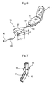
- FIG 7 shows a coin passage 81 (in the box B) continuing downward from the coin slot 62 shown in Figure 5.
- the coin passage 81 is formed with a chute guiding member 82, and the above-mentioned sensor switch 64 is U-shaped and disposed as to hold the chute guiding member 82.
- the portable charger 70 has a (thin) flat-box case 67 which has dimensions of, for example, a longitudinal side L 1 of f 10 to 15cm, a lateral side L 2 of 8 to 10 cm, and a thickness L 3 of 0.5 to 3 cm as to have a magnitude (size) easily stored in handbags, pockets, and bags to carry.
- Two thin cords 83 and 84 are protruding from the (portable) case 67.
- the (input) terminal 56 detachably connected to the terminal 55, is disposed on an end of the cord 83, and a terminal (for output) 85 is disposed on an end of the cord 84.
- the portable charger 70 is provided with the capacitor portion 57 composed of plural electric double-layer capacitors (condensers) 58 to accumulate electric energy supplied by the public charger 66 in connected state of the terminal 55 and the terminal 56, and a constant power output portion 60.
- the constant voltage output portion 60 of the portable charger 70 is detachably connected to the battery 8 of the mobile phone 10 to charge.
- the output terminal 85 is connected to a connecting terminal portion 86 of the mobile phone 10.
- the capacitor portion 57 of the portable charger 70 is composed of the plural electric double-layer capacitors 58 serially-connected to accumulate the electric energy from the public charger 66.
- the serially-connected electric double-layer capacitors 58 have electrostatic capacity C 1 , C 2 , ..., C n , and V 1 , V 2 , ..., V n indicate terminal voltage respectively.
- E is the supplied voltage of the capacitor portion 57 which corresponds to V 1 + V 2 + V 3 + ... + V n (namely, the total voltage).
- Time t 1 required to charge the serially-connected electric double-layer capacitors 58 by the capacitor portion 57 of large capacity is approximately 10 to 40 seconds.
- Many portable chargers 70 are efficiently charged in turn in convenience stores and public spaces. After the charge, the mobile phone 10 can be conveniently charged for sufficient time (generally 60 to 90 minutes) by the fully-charged portable charger 70 while it is carried (taken around). In other words, the portable charger 70 is restricted to the installation site of the public charger 66 in convenience stores and public spaces only for a short period of time, and taken around (carried) immediately after the boosting charge (of 10 to 40 seconds) keeping the mobile phone operational.
- the power source portion 51 is provided with a rectifier circuit 72 supplied with electric power by the commercial power source 14, a switching portion 73 and an auxiliary power source 74 supplied with electric energy by the rectifier circuit 72, and a high-frequency rectifier circuit 76 supplied with electric energy by the switching portion 73 through an output transformer 75. Further, the power source portion 51 is provided with a constant voltage control portion 77 and a PWM control portion 78 to detect the voltage of the electric energy supplied to the control portion 52 and the battery 53 (refer to Figure 8) by the high-frequency rectifier circuit 76 to make constant voltage, and a driving transformer 79 to transmit control signals from the PWM control portion 78 to the switching portion 73.
- the power source portion 51 shown in Figure 10 is composed of a rectifier 88 supplied with electric power from the commercial power source 14, smoothing capacitors 89 and 90, and a choke coil 91.
- the power source portion 51 is constructed as that electric power from the commercial power source 14 is supplied to a step-down transformer 92, then, sent to the rectifier 88, the smoothing capacitors 89 and 90, and the choke coil 91.
- the box-shaped public charger 66 is installed in convenience stores, hotels, stations, or other public spaces, connected to the commercial power source 14 to charge the battery 53 by float charging, and made stand-by in full-charged state.
- Many (units of) portable chargers 70 are preliminarily sold to many users.
- the user connects the terminal 56 of the portable charger 70 to the jack (terminal) 55 of the public charger 66 installed in convenience stores or public spaces and feeds a coin 63 to the coin slot 62 of the public charger 66.
- the sensor switch 64 detects the feeding of the coin 63, and boosting charge is conducted by the constant power control portion 54 with the current I 1 according to the detecting signal I 64 .
- the boosting charge is completed within 1 to 2 minutes utmost.
- the charging time is preferably 10 to 40 seconds, and more desirably 13 to 20 seconds. The completion of the charge is checked by the charging-state indicator 65.
- the portable charger 70 is separated from the public charger 66.
- the portable charger 70 can be carried (moved) immediately after the separation, stored in a handbag, a pocket, or a bag, and connected to the mobile phone 10 to charge while it is moved.
- a lithium-ion battery or a nickel-cadmium battery is used as the battery 8 of the mobile phone 10. Although it generally takes 60 to 90 minutes to reach full-charge for the characteristics of the battery 8, charging can be easily conducted with the small portable charger 70 while the user is moving (out). Therefore, inconvenience that the mobile phone is restricted to the installation site of the stationary public charger 66 is not caused.
- the charger for mobile phone of the present invention boosting charge is conducted as long as the electric double-layer capacitors 4 are not damaged. Therefore, restriction time for the charger is short. Further, the charger is easily made compact to take around in a bag or a pocket for charging the mobile phone 10 anytime when charging is needed in outing. And, the charger can sufficiently charge for a long time because the output portion 6 supply the power to the battery 8 with constant voltage.
- the charging site is not restricted to the installation site of the commercial power source 14 and charging can be conveniently conducted in outing by a motorcar because the charger can be charged not only by the commercial power source 14 but also by the car battery 13.
- the plural electric double-layer capacitors 4 can accumulate sufficient electric energy needed for charging the battery 8 of the mobile phone 10.
- the control circuit is made simple to be offered with a low price, and utility of the charger is very high because durability of the electric double-layer capacitor 4 can be sufficiently improved.
- boosting charge can be conducted (without a complicated control) for high utility.
- the mobile phone 10 is used much more conveniently than conventional mobile phones because the user can go out immediately after the charging of the charger 30 in hasty preparation, and the mobile phone 10 is slowly charged for sufficient time in outing.
- many portable chargers 70 can be charged in turn within a short period of time by one unit of the stationary public charger 66. Therefore, restriction time to the site of the stationary public charger 66 is short, and the user can move immediately after the charging of the portable charger 70. Further, the portable charger 70 is easily made compact to be carried, and the mobile phone 10 is charged anytime needed in outing by the charged portable charger 70 carried with the mobile phone 10. And, the mobile phone 10 is sufficiently charged for a long time because the constant voltage output portion 60 supplies constant voltage for charging the battery 8 of the mobile phone 10.
- the public charger 66 installed (fixed) in a place convenient for general users for usefulness, automatically starts to supply electric energy to the portable charger 70 when the coin is fed.
- the portable charger 70 can be sufficiently made light-weight and compact.
- serially-connected electric double-layer capacitors 58 are effective to make the portable charger 70 light-weight and compact, and able to accumulate sufficient electric energy needed for charging the battery 8 of the mobile phone 10.
- the stationary public charger 66 where the user is restricted, can charge rapidly enough.
- charging is slowly conducted as to be appropriate for the battery 8 (composed of a lithium-ion battery or a nickel-cadmium battery). This is rational and remarkably useful.
- the portable charger 70 is once charged in convenience stores, etc. when the user desires to charge quickly, then, while the user is out, the battery 8 of the mobile phone 10 is slowly charged for a long time.
Landscapes
- Engineering & Computer Science (AREA)
- Power Engineering (AREA)
- Charge And Discharge Circuits For Batteries Or The Like (AREA)
Applications Claiming Priority (4)
| Application Number | Priority Date | Filing Date | Title |
|---|---|---|---|
| JP2003029345A JP2004242429A (ja) | 2003-02-06 | 2003-02-06 | 携帯電話用充放電器及びその使用方法 |
| JP2003029345 | 2003-02-06 | ||
| JP2003035065 | 2003-02-13 | ||
| JP2003035065A JP2004248398A (ja) | 2003-02-13 | 2003-02-13 | 携帯電話器用充放電装置及び充電方法 |
Publications (2)
| Publication Number | Publication Date |
|---|---|
| EP1453176A2 true EP1453176A2 (de) | 2004-09-01 |
| EP1453176A3 EP1453176A3 (de) | 2006-10-04 |
Family
ID=32775219
Family Applications (1)
| Application Number | Title | Priority Date | Filing Date |
|---|---|---|---|
| EP04002430A Withdrawn EP1453176A3 (de) | 2003-02-06 | 2004-02-04 | Batterieladeschaltung für ein Mobiltelephon und Verfahren für den Betrieb desselben und Ladevorrichtung für ein Mobiltelephone und Lademethode für dasselbe |
Country Status (5)
| Country | Link |
|---|---|
| US (1) | US20040155631A1 (de) |
| EP (1) | EP1453176A3 (de) |
| KR (1) | KR20040071636A (de) |
| CN (1) | CN1533008A (de) |
| TW (1) | TWI231639B (de) |
Cited By (4)
| Publication number | Priority date | Publication date | Assignee | Title |
|---|---|---|---|---|
| EP2930821A1 (de) * | 2014-04-08 | 2015-10-14 | StoreDot Ltd. | Systeme und verfahren zur adaptiven schnellladung von mobilgeräten und geräten mit sporadischer verbindung zu einer energiequelle |
| EP3314719A4 (de) * | 2015-06-26 | 2019-01-16 | Intel Corporation | Elektronische vorrichtung mit direkter aufladung |
| US10879726B2 (en) | 2014-12-18 | 2020-12-29 | StoreDot Ltd. | Devices and methods for adaptive fast-charging of mobile devices |
| US11128152B2 (en) | 2014-04-08 | 2021-09-21 | StoreDot Ltd. | Systems and methods for adaptive fast-charging for mobile devices and devices having sporadic power-source connection |
Families Citing this family (14)
| Publication number | Priority date | Publication date | Assignee | Title |
|---|---|---|---|---|
| KR101043761B1 (ko) * | 2004-09-10 | 2011-06-22 | 엘지전자 주식회사 | 예비 충전지를 구비한 충전용 배터리 충전장치 |
| KR100784305B1 (ko) * | 2006-02-17 | 2007-12-13 | 안성훈 | 다기능 휴대형 충전기 |
| KR100826149B1 (ko) * | 2006-11-24 | 2008-04-30 | 국방과학연구소 | 소화기 사격통제장치용 순간 고 전력 전원공급장치 및 방법 |
| WO2011014142A1 (en) | 2009-07-30 | 2011-02-03 | Orna Vaknin | Public cellular telephone charging station |
| JP5647057B2 (ja) * | 2010-05-19 | 2014-12-24 | 株式会社日立製作所 | 充電装置、充電制御ユニット及び充電制御方法 |
| US9362764B2 (en) * | 2012-01-23 | 2016-06-07 | Tsuga Engineering Llc | Portable rechargeable power supply |
| US20160020618A1 (en) * | 2014-07-21 | 2016-01-21 | Ford Global Technologies, Llc | Fast Charge Algorithms for Lithium-Ion Batteries |
| US9614371B1 (en) | 2014-08-06 | 2017-04-04 | Tsuga Engineering Llc | Interface systems and methods for portable structures |
| KR102608659B1 (ko) | 2014-11-13 | 2023-12-04 | 잽고 엘티디 | 배터리 충전기 |
| CN104682834A (zh) * | 2015-03-16 | 2015-06-03 | 深圳市煊阳科技有限公司 | 一种节能充电器 |
| US10333323B2 (en) * | 2015-03-24 | 2019-06-25 | Horizon Hobby, LLC | Systems and methods for battery charger with internal power source |
| GB2544775B (en) * | 2015-11-26 | 2021-07-21 | Zapgo Ltd | Portable electronic device |
| CN109066857B (zh) * | 2018-08-15 | 2021-12-24 | 重庆七腾科技有限公司 | 对巡逻机器人进行充电的方法及充电机器人 |
| CN112448054B (zh) * | 2019-08-30 | 2023-02-17 | 北京小米移动软件有限公司 | 移动终端的充电方法、装置、终端及存储介质 |
Family Cites Families (8)
| Publication number | Priority date | Publication date | Assignee | Title |
|---|---|---|---|---|
| US5263565A (en) * | 1992-11-23 | 1993-11-23 | Wilkinson Rudolph P | Combination parking meter and electric energy dispensing apparatus and method |
| US5423407A (en) * | 1994-01-27 | 1995-06-13 | Nikolic; Thomas | Systems for providing electrical power in response to deposited coins |
| US5969505A (en) * | 1996-12-05 | 1999-10-19 | Jeol Ltd. | Charging system for charging capacitors of a capacitor bank |
| US5901056A (en) * | 1997-12-03 | 1999-05-04 | Hung; Sheng-Chuan | DC power supply device adapted to operate with an AC power supply or with a car battery via a cigarette lighter |
| JP2000253510A (ja) * | 1999-03-01 | 2000-09-14 | Meidensha Corp | バッテリーカーの駆動回路 |
| JP3679681B2 (ja) * | 2000-04-05 | 2005-08-03 | ペンタックス株式会社 | 電源装置及び電気二重層コンデンサの充電方法 |
| JP2003299255A (ja) * | 2002-04-02 | 2003-10-17 | Nippon Telegr & Teleph Corp <Ntt> | 携帯型充電装置 |
| US6737830B2 (en) * | 2002-07-02 | 2004-05-18 | Hewlett-Packard Development Company, L.P. | Battery charging using a portable energy storage device |
-
2004
- 2004-01-30 TW TW093102236A patent/TWI231639B/zh not_active IP Right Cessation
- 2004-02-04 US US10/770,469 patent/US20040155631A1/en not_active Abandoned
- 2004-02-04 EP EP04002430A patent/EP1453176A3/de not_active Withdrawn
- 2004-02-05 KR KR1020040007429A patent/KR20040071636A/ko not_active Ceased
- 2004-02-05 CN CNA2004100397489A patent/CN1533008A/zh active Pending
Cited By (4)
| Publication number | Priority date | Publication date | Assignee | Title |
|---|---|---|---|---|
| EP2930821A1 (de) * | 2014-04-08 | 2015-10-14 | StoreDot Ltd. | Systeme und verfahren zur adaptiven schnellladung von mobilgeräten und geräten mit sporadischer verbindung zu einer energiequelle |
| US11128152B2 (en) | 2014-04-08 | 2021-09-21 | StoreDot Ltd. | Systems and methods for adaptive fast-charging for mobile devices and devices having sporadic power-source connection |
| US10879726B2 (en) | 2014-12-18 | 2020-12-29 | StoreDot Ltd. | Devices and methods for adaptive fast-charging of mobile devices |
| EP3314719A4 (de) * | 2015-06-26 | 2019-01-16 | Intel Corporation | Elektronische vorrichtung mit direkter aufladung |
Also Published As
| Publication number | Publication date |
|---|---|
| TW200415838A (en) | 2004-08-16 |
| CN1533008A (zh) | 2004-09-29 |
| KR20040071636A (ko) | 2004-08-12 |
| US20040155631A1 (en) | 2004-08-12 |
| TWI231639B (en) | 2005-04-21 |
| EP1453176A3 (de) | 2006-10-04 |
Similar Documents
| Publication | Publication Date | Title |
|---|---|---|
| EP1453176A2 (de) | Batterieladeschaltung für ein Mobiltelephon und Verfahren für den Betrieb desselben und Ladevorrichtung für ein Mobiltelephone und Lademethode für dasselbe | |
| US20250389247A1 (en) | Multifunctional Battery Booster | |
| KR101197243B1 (ko) | 휴대용 대용량 전원 공급장치 | |
| JP3183420U (ja) | 携帯式ワイヤレス充電器 | |
| US11349386B2 (en) | Apparatus and method for charging battery of vehicle | |
| CN1071057C (zh) | 电池充电装置 | |
| US7151356B1 (en) | Retractable cord power adapter and battery pack | |
| JP4507191B2 (ja) | 電池の充電装置 | |
| JP2003299255A (ja) | 携帯型充電装置 | |
| EP2501016A2 (de) | Integriertes Batterieladegerät | |
| EP0479249A2 (de) | Ladevorrichtung für elektronisches Gerät | |
| JP2008306925A (ja) | 充電装置 | |
| JP2013005527A (ja) | 非接触充電システム及び非接触充電方法 | |
| US20070080663A1 (en) | Portable charger with a rechargeable back-up battery | |
| JP2005094862A (ja) | 非接触給電方法及び非接触給電装置 | |
| EP3379685A1 (de) | Starthilfevorrichtung zum wiederaufladen einer entladenen batterie von transportmitteln | |
| JP5573125B2 (ja) | 充電スタンド及び車両の充電方法 | |
| US7688026B2 (en) | Energy storage mobile charging adapter and energy storing method for the same | |
| JPH08503599A (ja) | 追従型外部電源 | |
| CN210526333U (zh) | 移动充电车 | |
| JP3765885B2 (ja) | 電気自動車の蓄電装置 | |
| JP4085794B2 (ja) | 電池の充電装置 | |
| JP2006049331A (ja) | 携帯電話器用充放電装置及び充電方法 | |
| CN201230216Y (zh) | 高频充电器 | |
| JP2004288537A (ja) | パック電池、二次電池充電装置および二次電池充電方法 |
Legal Events
| Date | Code | Title | Description |
|---|---|---|---|
| PUAI | Public reference made under article 153(3) epc to a published international application that has entered the european phase |
Free format text: ORIGINAL CODE: 0009012 |
|
| AK | Designated contracting states |
Kind code of ref document: A2 Designated state(s): AT BE BG CH CY CZ DE DK EE ES FI FR GB GR HU IE IT LI LU MC NL PT RO SE SI SK TR |
|
| AX | Request for extension of the european patent |
Extension state: AL LT LV MK |
|
| RIC1 | Information provided on ipc code assigned before grant |
Ipc: H01G 9/00 20060101ALI20060607BHEP Ipc: H02J 7/34 20060101ALI20060607BHEP Ipc: H02J 7/00 20060101AFI20040714BHEP |
|
| PUAL | Search report despatched |
Free format text: ORIGINAL CODE: 0009013 |
|
| AK | Designated contracting states |
Kind code of ref document: A3 Designated state(s): AT BE BG CH CY CZ DE DK EE ES FI FR GB GR HU IE IT LI LU MC NL PT RO SE SI SK TR |
|
| AX | Request for extension of the european patent |
Extension state: AL LT LV MK |
|
| AKX | Designation fees paid | ||
| STAA | Information on the status of an ep patent application or granted ep patent |
Free format text: STATUS: THE APPLICATION IS DEEMED TO BE WITHDRAWN |
|
| 18D | Application deemed to be withdrawn |
Effective date: 20070405 |
|
| REG | Reference to a national code |
Ref country code: DE Ref legal event code: 8566 |