EP1452994B1 - Manual IC card reader - Google Patents
Manual IC card reader Download PDFInfo
- Publication number
- EP1452994B1 EP1452994B1 EP04005716A EP04005716A EP1452994B1 EP 1452994 B1 EP1452994 B1 EP 1452994B1 EP 04005716 A EP04005716 A EP 04005716A EP 04005716 A EP04005716 A EP 04005716A EP 1452994 B1 EP1452994 B1 EP 1452994B1
- Authority
- EP
- European Patent Office
- Prior art keywords
- card
- contacts
- contact
- block
- insertion direction
- Prior art date
- Legal status (The legal status is an assumption and is not a legal conclusion. Google has not performed a legal analysis and makes no representation as to the accuracy of the status listed.)
- Expired - Lifetime
Links
Images

Classifications
-
- G—PHYSICS
- G06—COMPUTING; CALCULATING OR COUNTING
- G06K—GRAPHICAL DATA READING; PRESENTATION OF DATA; RECORD CARRIERS; HANDLING RECORD CARRIERS
- G06K7/00—Methods or arrangements for sensing record carriers, e.g. for reading patterns
- G06K7/0013—Methods or arrangements for sensing record carriers, e.g. for reading patterns by galvanic contacts, e.g. card connectors for ISO-7816 compliant smart cards or memory cards, e.g. SD card readers
- G06K7/0021—Methods or arrangements for sensing record carriers, e.g. for reading patterns by galvanic contacts, e.g. card connectors for ISO-7816 compliant smart cards or memory cards, e.g. SD card readers for reading/sensing record carriers having surface contacts
-
- G—PHYSICS
- G06—COMPUTING; CALCULATING OR COUNTING
- G06K—GRAPHICAL DATA READING; PRESENTATION OF DATA; RECORD CARRIERS; HANDLING RECORD CARRIERS
- G06K13/00—Conveying record carriers from one station to another, e.g. from stack to punching mechanism
- G06K13/02—Conveying record carriers from one station to another, e.g. from stack to punching mechanism the record carrier having longitudinal dimension comparable with transverse dimension, e.g. punched card
- G06K13/08—Feeding or discharging cards
-
- G—PHYSICS
- G06—COMPUTING; CALCULATING OR COUNTING
- G06K—GRAPHICAL DATA READING; PRESENTATION OF DATA; RECORD CARRIERS; HANDLING RECORD CARRIERS
- G06K7/00—Methods or arrangements for sensing record carriers, e.g. for reading patterns
- G06K7/0013—Methods or arrangements for sensing record carriers, e.g. for reading patterns by galvanic contacts, e.g. card connectors for ISO-7816 compliant smart cards or memory cards, e.g. SD card readers
- G06K7/0021—Methods or arrangements for sensing record carriers, e.g. for reading patterns by galvanic contacts, e.g. card connectors for ISO-7816 compliant smart cards or memory cards, e.g. SD card readers for reading/sensing record carriers having surface contacts
- G06K7/0026—Methods or arrangements for sensing record carriers, e.g. for reading patterns by galvanic contacts, e.g. card connectors for ISO-7816 compliant smart cards or memory cards, e.g. SD card readers for reading/sensing record carriers having surface contacts the galvanic contacts of the connector adapted for landing on the contacts of the card upon card insertion
Definitions
- the present invention relates to a manual card reader and a manual IC card reader.
- the present invention relates to a manual IC card reader which pushes down an IC contacts block with the insertion of an IC card, to project it toward a card pathway.
- IC card readers cards are inserted and removed by hand
- an IC contacts spring needs to be contacted with a contact terminal pattern on an IC card that has been stopped at a predetermined position when performing a data communication with the card.
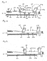
- an IC contacts block 501 is supported by links 502, 503 to project toward a card pathway 504, a stop 508 is formed at the IC contacts block 501, and the IC contacts block 501 is pushed down for contact as the IC card 505 is inserted.
- the IC contacts block 501 is pulled opposite to the card insertion direction by a spring 506.
- the inserted IC card 505 hits against the stop 508, and moves the IC contacts block 501 stretching the spring 506. Therefore, the IC contacts block 501 is gradually lowered as it is moved together with the IC card 505, and brings the IC contacts spring 507 into contact with the contact terminal pattern on the IC card 105. Since the IC card 505 is accurately positioned by hitting against the stop 508 of the IC contacts block 501, the IC contacts spring 507 of the IC contacts block 501 precisely contacts the corresponding contact terminal pattern on the IC card 505.
- a code, 510 indicates a magnetic head
- a code, 511 indicates a foreign matter discharge opening
- the IC contacts block 501 is pushed down as the IC card 505 is inserted, and accordingly the friction between the IC card 505 and the card running surface 509 of the card pathway 504 is increased.
- the IC contacts spring 507 gradually but strongly presses the IC card 505 down onto the card running surface 509. This gradually increases friction that in turn becomes an insertion load on the IC card 505.
- the IC contacts block 501 As the IC contacts block 501 is lowered, the IC contacts springs 507 arranged in two rows strongly and simultaneously press the IC card 505 down onto the card running surface 509. This increases friction that in turn becomes an insertion load on the IC card 505. Therefore, the force necessary to bring the card in increases abruptly during the insertion, thus deteriorating the operability of the card insertion.
- a user may misunderstand a sudden increase of the insertion load during the card insertion as the completion of the card insertion. If the user mistakenly stops pushing in the IC card 505 during the insertion, not only can an excellent contact not be obtained between the contact terminal pattern on the IC card 505 and the IC contacts spring 507 on the IC contacts block 501, but also an operational error may be caused due to an unusual contact position of the IC contacts spring 507.
- EP 0 399 763 A2 representing the closest prior art from which the present invention proceeds, discloses an IC card reader comprising an attaching/detaching mechanism which moves an IC contacts block into contact with a contact terminal pattern on an IC card whereby a lag is caused in the card contact starting time between first contacts and second contacts on the IC contacts block.
- an IC card reader comprising an attaching/detaching mechanism adapted to move an IC contacts block into contact with or away from a contact terminal pattern on an IC card such that a lag is caused in the card contact starting time between first contacts and second contacts on said IC contacts block, characterized in that said attaching/detaching mechanism) is a link mechanism, in which the lengths of rear and front links arranged in the card insertion direction are different so as to cause the time lag in the card contact starting time between rear contacts and front contacts arranged in the card insertion direction.
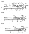
- FIGs. 1 through FIGs. 7 illustrate a preferred embodiment of an IC card reader of the present invention.
- IC card reader comprises an attaching/detaching mechanism 233 that moves an IC contacts block 201 into contact with or away from a contact terminal pattern on an IC card 202.
- the attaching/detaching mechanism 233 brings a front contacts 208a and a rear contacts 208b on the IC contacts block 201 arranged in the card insertion direction shown by arrow, C, in the figure (hereinafter, denoted as the card insertion direction C) into contact with the contact terminal pattern on the IC card 202 such that a time lag is caused in contact starting time thereof with the IC card 202 (in this specification, simply called as "card contact starting time").
- the IC card reader in this embodiment is a manual card reader; in which the IC contacts block is pushed down upon the insertion of the IC card 202 to contact the contact terminal pattern on the IC card 202 so that a data communication is made with the IC card 202.
- the attaching/detaching mechanism 233 in this embodiment is, for example, a link mechanism (hereinafter, the attaching/detaching mechanism is called as the link mechanism 233).
- the attaching/detaching mechanism is called as the link mechanism 233.
- the IC contacts block 201 is mounted onto an IC card reader (not illustrated) via the links 217a and 217b.
- Each of the links 217a and 217b has holes at both ends, which are rotatably fitted to supporting shafts 212a, 212b, 216a, 216b respectively.
- the IC contacts block in this embodiment is supported by four links 217a, 217a, 217b, 217b that make pairs facing in the perpendicular direction to the plane as shown in FIG. 7.
- the link mechanism 233 consists of four links 217a, 217a, 217b, and 217b so that the IC contacts block 201 is capable of contacting/separating with respect to the contact terminal pattern on the IC card 202.
- the rear link 217a in the card insertion direction C is longer than the front link 217b in the card insertion C.
- the supporting shafts 212a and 212b are provided such that the IC contacts block 201 comes in parallel to the IC card 202 when the links 217a and 217b are in perpendicular, i.e., when the IC contacts block 201 is at closest to the IC card 202.
- the supporting shaft 212b is provided lower than the supporting shaft 212a in FIG. 1 so that the supporting shafts 216a and 216b are positioned at equal distances from the bottom surface of the card pathway 206 when the links 217a and 217b are in perpendicular.
- a circle 234 shown by a dash-dot line in FIG. 1 is a trace of the link 217b rotated about the supporting shaft 212b.
- a circle 235 shown by a dash-dot line in FIG. 1 is a trace of the link 217a rotated about the supporting shaft 212a.
- a forcing means for example, a coil spring 207
- a coil spring 207 is bridged from the supporting shaft 216b to a fixed point, n, in the IC card reader to lift the IC contacts block 201 in the upper left direction in the figure as illustrated in FIGs. 1 and 4, pulling the IC contacts block 201 away from a bottom frame 205. Consequently, a force against the gravity (the perpendicular force) of the IC contacts block 201 is generated, and the IC contacts block 201 is positioned away from the card pathway 206 (in this embodiment, this position is hereinafter called a standby position 201a). At this time, the IC contacts block 201 is on standby with a position slightly inclined in the upper left direction in FIG. 1 due to the different lengths of the links 217a and 217b.
- the right end of the IC contacts block 201 in FIG. 1 is formed as a projecting portion 230; the end surface of the projecting portion 230 close to the card insertion slot is a card contact surface 210 that contacts the card incoming edge 202a. Also, on the side of another end surface of the projecting portion 230 opposite the card contact surface 210, a stopper 213 fixed at a fixed point in the card reader (not illustrated) is provided for controlling the movement of the IC contacts block 201.
- the IC contacts block 201 illustrated in FIGs. 3, 6, and 7 contacts the stopper 213 in a position at which the supporting shaft 216a is positioned slightly further deeper in the card insertion direction, C, than the supporting shaft 212a (in this embodiment, this position is hereinafter called a stopper contact position 201c).
- a positional discrepancy L is created between the perpendicular line from the supporting shaft 216a to the bottom frame 205 and that from the supporting shaft 212a to the bottom frame 205.
- the IC contacts block 201 moves back maintaining the card incoming edge 202a and card contact surface 210 contacted together; and stops at the position at which the links 217a and 217b are in perpendicular to the bottom frame 205, that is, the position at which the contacts 208a, 208b press the IC card 203 with the strongest contact pressure.
- a contacts terminal 208 is provided on the surface of the IC contact block 201 facing the bottom frame 205.
- the contacts 208a, 208b are brought into contact with the contact terminal pattern on the IC card 202 when the IC card 202 is inserted at the card insertion slot through the card pathway 206.
- the contacts terminal 208 is composed of a conductive flat spring or linear spring; the contacts 208a and contacts 208b are respectively formed at a predetermined diagonal distance away from the supporting shafts 218, and pushed toward the IC card 202 in the bottom frame 205 direction pivoting on the supporting shaft 218 as a supporting point (fulcrum).
- a plurality of the contact terminals 208 are arranged in the supporting shafts 212a, 212b direction, and the contacts 208a and 208b are arranged symmetrical about the controlling member 215 or in the same direction.
- one end of the contacts terminal 208 is a connecting portion 214, which is electrically connected to a predetermined circuit.
- the other end is a controlling portion 209 bent in L-shape, which contacts a flange surface 219 of a contact position controlling member 214 to control the lowest positions of the contacts 208a, 208b.
- the contacts terminal 208 is to be positioned to nearly come into contact with the bottom frame 205 when the IC card 202 is not inserted and the IC contacts block 201 is in the stopper contact position 201c.
- the contacts 208a, 208b are pushed up from the flange surface 219 of the contacts position controlling member 215 by the IC card 202, and a pressure equal to the repelling force of the contacts 208a, 208b is applied on the IC card 202 (See FIG. 4 through FIG. 6).
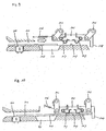
- the IC contacts block 201 illustrated in FIG. 1 and FIG. 4 is in the standby position 201a. With this condition, the IC card 202 is inserted at the card insertion slot in the card insertion direction C. Then, the card incoming edge 202a hits the projecting portion 230 of the IC contacts block 201 in the standby position 201 a; as the IC card 202 is pushed in by the force stronger than the spring force of the spring 207, the IC contacts block 201 is moved together with and approaching the IC card 202 by the link mechanism 233 until the stopper 213 stops the movement thereof.
- the IC contacts block 201 moves, not in parallel, but diagonal to the card insertion direction, C, to approach and make contact with the IC card 202. With this, a time lag is caused in the card contact starting time between the contacts 208a and the contacts 208b.
- the rear contacts 208a in the card insertion direction C makes contact with the corresponding contact terminal pattern on the IC card 202 first, and then the front contacts 208b in the card insertion direction C comes into contact with the corresponding contact terminal pattern on the IC card 202 (see FIG. 2 and FIG. 4).
- the contacts 208a, 208b are lifted up from the flange surface 219 of the contact position controlling member 215, and the pressure equal to the spring force is applied on the IC card 202 by the contacts 208a, 208b..
- the contacts 208a and the contacts 208b contact the contact terminal pattern on the IC card 202 not simultaneously, but in a delayed manner. Therefore, an abrupt increase of the card insertion load, normally caused by the contact between the IC contacts block 201 and the IC card 202; can be prevented.
- the IC contacts block. 201 soon contacts the-stopper 213 and comes in the stopper contact position 201c illustrated in FIGs. 3, 6, and 7.
- the supporting shafts 216a, 216b are respectively at the position slightly (the distance, L, shown in FIG. 7, for example) passing the supporting shafts 212a, 212b in the card insertion direction C. With this, even though receiving the vibration or reaction caused when the IC contacts block 201.
- the IC contacts block 201 stops in the position at which the contact pressure of the contacts 208a and 208b on the IC card 202 is strongest, i.e., at which the links 217a, 217b are in perpendicular to the bottom frame 205, so that the contacts 208a, 208b are prevented from coming off the contact terminal pattern on the IC card 202.
- the IC card reader communicates with the IC card 202 through the contacts 208a, 208b.
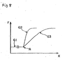
- FIG. 8 shows an, example of the relationship between a moving distance, X, of the IC card 202 from the card insertion slot and a card insertion load, F.
- the portion shown by G1 in the figure indicates the condition of the load before the IC card 202 makes contact with the IC contacts block 201.
- the card insertion load at this time is caused by a friction with the card pathway or a pad pressure of the magnetic head (the pressure of the magnetic head to press the pad) when the device is a card reader commonly used for IC cards 202 and magnetic cards; the value thereof is very small compared to the values after the IC card makes contact with the IC contacts block 201 and is mostly constant regardless of the moving distance of the IC card 202.
- a point, A, in the figure indicates the starting point of the contact between the IC card 202 and IC contacts block 201.
- the portion shown by G2 in the figure is obtained in a conventional IC card reader in which the rear contacts and front contacts on the IC contacts block 201 arranged in the card insertion direction make contact with the IC card at the same time.
- the card insertion load abruptly increases after the point, A.
- the portion shown by G3 in the figure is obtained in the IC card reader of the present invention.
- the front contacts 208b and rear contacts 208a arranged in the card insertion direction press the IC card 202 in a delayed manner, not simultaneously ; therefore, the increase of the card insertion load, F, with respect to the moving distance, X, of the IC card 202 is relatively moderate.
- the card insertion load is prevented from an abrupt increase, but increases moderately. Accordingly, the probability of error in magnetic data reading is decreased.
- the user of the IC card reader will not misunderstand the increase of the insertion load as the completion of the insertion, thus improving reliability of the communication with the IC card 202.
- the above embodiment uses the link mechanism for the attaching/detaching mechanism 233 to move the IC contacts block 201 into contact with or away from the contact terminal pattern on the IC card 202, but the mechanism is not limited to this.
- a cam mechanism may be used for the attaching/detaching mechanism 233 to cause a lag in the card contact starting time between the rear contacts 208a and front contacts 208b on the IC contacts block 201 in the card insertion direction, C, to contact the terminal pattern on the IC card 202.
- the front contacts 208b and rear contacts 208a in the card insertion direction, C press the IC card 202 in a delayed manner, not simultaneously; therefore, the probability of error in magnetic data reading can be decreased. Furthermore, the user of the IC card reader will not misunderstand the increase of the insertion load as the completion of the insertion, thus improving reliability of the communication with the IC card 202.
- the attaching/detaching mechanism 233 is configured such that the rear contacts 208a in the card insertion direction, C, contacts, the IC card 202 first, and then the front contacts 208b in the card insertion direction, C, contacts the IC card 202.
- the embodiment is not limited to this. According to the situation, the front contacts 208b in the card insertion direction, C, may contact the IC card 202 first, and then the rear contacts 208a may contact the IC card 202.
- the attaching/detaching mechanism is configured to cause a lag in the card contact starting time between the rear contacts and the front contacts on the IC contacts block arranged in the card insertion direction to contact the contact terminal pattern on the IC card. Therefore, the card insertion load can be prevented from increasing abruptly, but changes moderately. Consequently, the probability of error in magnetic data reading is decreased. Furthermore, the user will not misunderstand the increase of the card insertion load as the completion of the insertion, thus improving reliability of communication with the IC card.
- the attaching/detaching mechanism is a link mechanism; by changing the lengths of the rear link and front link arranged in the card insertion direction, a lag is caused in the card contact starting time between the rear contacts and the front contacts arranged in the card insertion direction. Therefore, the above useful effects can be obtained with a simple configuration and at low cost.
Description
- The present invention relates to a manual card reader and a manual IC card reader.
- More specifically, the present invention ,relates to a manual IC card reader which pushes down an IC contacts block with the insertion of an IC card, to project it toward a card pathway.
- In some IC card readers, cards are inserted and removed by hand In IC card readers, an IC contacts spring needs to be contacted with a contact terminal pattern on an IC card that has been stopped at a predetermined position when performing a data communication with the card.
- For this reason, in a conventional manual IC card reader as illustrated in FIGs. 9 and 10, an IC contacts block 501 is supported by
links 502, 503 to project toward a card pathway 504, a stop 508 is formed at the IC contacts block 501, and the IC contacts block 501 is pushed down for contact as the IC card 505 is inserted. The IC contacts block 501 is pulled opposite to the card insertion direction by a spring 506. The inserted IC card 505 hits against the stop 508, and moves the IC contacts block 501 stretching the spring 506. Therefore, the IC contacts block 501 is gradually lowered as it is moved together with the IC card 505, and brings the IC contacts spring 507 into contact with the contact terminal pattern on theIC card 105. Since the IC card 505 is accurately positioned by hitting against the stop 508 of the IC contacts block 501, the IC contacts spring 507 of the IC contacts block 501 precisely contacts the corresponding contact terminal pattern on the IC card 505. - Note that a code, 510, indicates a magnetic head, and a code, 511, indicates a foreign matter discharge opening.
- However, in the above mentioned manual IC card reader, the IC contacts block 501 is pushed down as the IC card 505 is inserted, and accordingly the friction between the IC card 505 and the card running surface 509 of the card pathway 504 is increased.
- In other words, as the IC contacts block 501 is lowered, the IC contacts spring 507 gradually but strongly presses the IC card 505 down onto the card running surface 509. This gradually increases friction that in turn becomes an insertion load on the IC card 505.
- Furthermore, as the IC contacts block 501 is lowered, the IC contacts springs 507 arranged in two rows strongly and simultaneously press the IC card 505 down onto the card running surface 509. This increases friction that in turn becomes an insertion load on the IC card 505. Therefore, the force necessary to bring the card in increases abruptly during the insertion, thus deteriorating the operability of the card insertion.
- Also, a user may misunderstand a sudden increase of the insertion load during the card insertion as the completion of the card insertion. If the user mistakenly stops pushing in the IC card 505 during the insertion, not only can an excellent contact not be obtained between the contact terminal pattern on the IC card 505 and the IC contacts spring 507 on the IC contacts block 501, but also an operational error may be caused due to an unusual contact position of the IC contacts spring 507.
- EP 0 399 763 A2, representing the closest prior art from which the present invention proceeds, discloses an IC card reader comprising an attaching/detaching mechanism which moves an IC contacts block into contact with a contact terminal pattern on an IC card whereby a lag is caused in the card contact starting time between first contacts and second contacts on the IC contacts block.
- According to the present invention, there is now provided an IC card reader comprising an attaching/detaching mechanism adapted to move an IC contacts block into contact with or away from a contact terminal pattern on an IC card such that a lag is caused in the card contact starting time between first contacts and second contacts on said IC contacts block, characterized in that said attaching/detaching mechanism) is a link mechanism, in which the lengths of rear and front links arranged in the card insertion direction are different so as to cause the time lag in the card contact starting time between rear contacts and front contacts arranged in the card insertion direction.
- A preferred embodiment of the present invention will be described in detail hereinafter with reference to the accompanying drawings, wherein
- FIG. 1 illustrates a side view of an IC card reader of the present invention in one form of an embodiment, showing that an. IC contacts block is in a standby position;
- FIG. 2 is a side view of the IC card reader, showing that both rear and front contacts of the. IC-contacts block arranged in the card insertion direction are in contact with the IC card;
- FIG. 3 is a side view of the IC card reader, showing that the IC contacts block is in contact with a stopper,
- FIG. 4 is a cross-sectional side view of FIG. 1, showing the position of the contacts of the IC contacts block;
- FIG. 5 is a cross-sectional side view of FIG. 2, showing the position of the contacts of the IC contacts block;
- FIG. 6 is a cross-sectional side view of FIG. 3, showing the position of the contacts of the IC contacts block;
- FIG. 7 is a magnified side cross-sectional view of FIG. 3, showing the position of the contacts of the IC contacts block;
- FIG. 8 is a graph showing an example of a relation between the moving distance of the IC card (horizontal axis) from the card insertion slot and the card insertion load (vertical axis);
- FIG. 9 illustrates an IC contacts block of a conventional manual IC card reader, which is in a condition before the IC card is inserted; and
- FIG. 10 illustrates the IC contacts block of the conventional manual IC card reader, which is in a condition when the IC card is inserted to the card stop position.
- FIGs. 1 through FIGs. 7 illustrate a preferred embodiment of an IC card reader of the present invention. This. IC card reader comprises an attaching/
detaching mechanism 233 that moves anIC contacts block 201 into contact with or away from a contact terminal pattern on anIC card 202. The attaching/detachingmechanism 233 brings a front contacts 208a and arear contacts 208b on theIC contacts block 201 arranged in the card insertion direction shown by arrow, C, in the figure (hereinafter, denoted as the card insertion direction C) into contact with the contact terminal pattern on theIC card 202 such that a time lag is caused in contact starting time thereof with the IC card 202 (in this specification, simply called as "card contact starting time"). - The IC card reader in this embodiment is a manual card reader; in which the IC contacts block is pushed down upon the insertion of the
IC card 202 to contact the contact terminal pattern on theIC card 202 so that a data communication is made with theIC card 202. - The attaching/
detaching mechanism 233 in this embodiment is, for example, a link mechanism (hereinafter, the attaching/detaching mechanism is called as the link mechanism 233). By changing the lengths of arear link 217a and a front link 217b arranged in the card insertion direction, C, a time lag is caused in the card contact starting time between the contacts 208a and thecontacts 208b. - The
IC contacts block 201 is mounted onto an IC card reader (not illustrated) via thelinks 217a and 217b. Each of thelinks 217a and 217b has holes at both ends, which are rotatably fitted to supportingshafts 212a, 212b, 216a, 216b respectively. Note that the IC contacts block in this embodiment is supported by fourlinks link mechanism 233 consists of fourlinks IC contacts block 201 is capable of contacting/separating with respect to the contact terminal pattern on theIC card 202. - In this embodiment, the
rear link 217a in the card insertion direction C is longer than the front link 217b in the card insertion C. The supportingshafts 212a and 212b are provided such that theIC contacts block 201 comes in parallel to theIC card 202 when thelinks 217a and 217b are in perpendicular, i.e., when theIC contacts block 201 is at closest to theIC card 202. For example, the supporting shaft 212b is provided lower than the supportingshaft 212a in FIG. 1 so that the supporting shafts 216a and 216b are positioned at equal distances from the bottom surface of thecard pathway 206 when thelinks 217a and 217b are in perpendicular. Note that a circle 234 shown by a dash-dot line in FIG. 1 is a trace of the link 217b rotated about the supporting shaft 212b. Also, acircle 235 shown by a dash-dot line in FIG. 1 is a trace of thelink 217a rotated about the supportingshaft 212a. - A forcing means, for example, a
coil spring 207, is bridged from the supporting shaft 216b to a fixed point, n, in the IC card reader to lift theIC contacts block 201 in the upper left direction in the figure as illustrated in FIGs. 1 and 4, pulling theIC contacts block 201 away from abottom frame 205. Consequently, a force against the gravity (the perpendicular force) of theIC contacts block 201 is generated, and theIC contacts block 201 is positioned away from the card pathway 206 (in this embodiment, this position is hereinafter called a standby position 201a). At this time, theIC contacts block 201 is on standby with a position slightly inclined in the upper left direction in FIG. 1 due to the different lengths of thelinks 217a and 217b. - The right end of the
IC contacts block 201 in FIG. 1 is formed as a projectingportion 230; the end surface of the projectingportion 230 close to the card insertion slot is acard contact surface 210 that contacts the card incoming edge 202a. Also, on the side of another end surface of the projectingportion 230 opposite thecard contact surface 210, astopper 213 fixed at a fixed point in the card reader (not illustrated) is provided for controlling the movement of theIC contacts block 201. - In this embodiment, the
IC contacts block 201 illustrated in FIGs. 3, 6, and 7 contacts thestopper 213 in a position at which the supporting shaft 216a is positioned slightly further deeper in the card insertion direction, C, than the supportingshaft 212a (in this embodiment, this position is hereinafter called astopper contact position 201c). As illustrated in FIG. 7, in thestopper contact position 201 c, a positional discrepancy L is created between the perpendicular line from the supporting shaft 216a to thebottom frame 205 and that from the supportingshaft 212a to thebottom frame 205. With this configuration, if theIC contacts block 201 is returned toward the card insertion slot due to vibration or reaction caused when theIC contacts block 201 contacts thestopper 213 upon insertion of theIC card 202, theIC contacts block 201 moves back maintaining the card incoming edge 202a andcard contact surface 210 contacted together; and stops at the position at which thelinks 217a and 217b are in perpendicular to thebottom frame 205, that is, the position at which thecontacts 208a, 208b press the IC card 203 with the strongest contact pressure. - A
contacts terminal 208 is provided on the surface of theIC contact block 201 facing thebottom frame 205. Thecontacts 208a, 208b are brought into contact with the contact terminal pattern on theIC card 202 when theIC card 202 is inserted at the card insertion slot through thecard pathway 206. Thecontacts terminal 208 is composed of a conductive flat spring or linear spring; the contacts 208a andcontacts 208b are respectively formed at a predetermined diagonal distance away from the supportingshafts 218, and pushed toward theIC card 202 in thebottom frame 205 direction pivoting on the supportingshaft 218 as a supporting point (fulcrum). A plurality of thecontact terminals 208 are arranged in the supportingshafts 212a, 212b direction, and thecontacts 208a and 208b are arranged symmetrical about the controllingmember 215 or in the same direction. Also, one end of thecontacts terminal 208 is a connectingportion 214, which is electrically connected to a predetermined circuit. In addition, the other end is a controllingportion 209 bent in L-shape, which contacts aflange surface 219 of a contactposition controlling member 214 to control the lowest positions of thecontacts 208a, 208b. Note that thecontacts terminal 208 is to be positioned to nearly come into contact with thebottom frame 205 when theIC card 202 is not inserted and theIC contacts block 201 is in thestopper contact position 201c. - In the figure, when the force to push the
contacts 208a, 208b upward is not exerted, the controllingportion 209 is lowered to contact theflange surface 219 of the contactsposition controlling member 215, as illustrated in FIG. 4. This means that, when the push-up force is exerted on thecontacts 208a, 208b in FIG. 4, the pressure at least equal to the repelling force (spring force/resilient force) of the contacts is applied to the card because the push-up force is created against the repelling force. In other words, as theIC card 202 is inserted into thecard pathway 206, thecontacts 208a, 208b are pushed up from theflange surface 219 of the contactsposition controlling member 215 by theIC card 202, and a pressure equal to the repelling force of thecontacts 208a, 208b is applied on the IC card 202 (See FIG. 4 through FIG. 6). - An example of the operation of the IC card reader having the above configuration will be described.
- The IC contacts block 201 illustrated in FIG. 1 and FIG. 4 is in the standby position 201a. With this condition, the
IC card 202 is inserted at the card insertion slot in the card insertion direction C. Then, the card incoming edge 202a hits the projectingportion 230 of the IC contacts block 201 in the standby position 201 a; as theIC card 202 is pushed in by the force stronger than the spring force of thespring 207, the IC contacts block 201 is moved together with and approaching theIC card 202 by thelink mechanism 233 until thestopper 213 stops the movement thereof. - Since the
links 217a, 217b differ in length from each other, the IC contacts block 201 moves, not in parallel, but diagonal to the card insertion direction, C, to approach and make contact with theIC card 202. With this, a time lag is caused in the card contact starting time between the contacts 208a and thecontacts 208b. In other words, the rear contacts 208a in the card insertion direction C makes contact with the corresponding contact terminal pattern on theIC card 202 first, and then thefront contacts 208b in the card insertion direction C comes into contact with the corresponding contact terminal pattern on the IC card 202 (see FIG. 2 and FIG. 4). - As the
IC card 202 moves, thecontacts 208a, 208b are lifted up from theflange surface 219 of the contactposition controlling member 215, and the pressure equal to the spring force is applied on theIC card 202 by thecontacts 208a, 208b.. At this time, the contacts 208a and thecontacts 208b contact the contact terminal pattern on theIC card 202 not simultaneously, but in a delayed manner. Therefore, an abrupt increase of the card insertion load, normally caused by the contact between the IC contacts block 201 and theIC card 202; can be prevented. - After the condition illustrated in FIG. 2 and FIG. 4, in which both of the
contacts 208a, 208b make contact with theIC card 202, the IC contacts block. 201 soon contacts the-stopper 213 and comes in thestopper contact position 201c illustrated in FIGs. 3, 6, and 7. At this time, the supporting shafts 216a, 216b are respectively at the position slightly (the distance, L, shown in FIG. 7, for example) passing the supportingshafts 212a, 212b in the card insertion direction C. With this, even though receiving the vibration or reaction caused when the IC contacts block 201. abuts the stopper, the IC contacts block 201 stops in the position at which the contact pressure of thecontacts 208a and 208b on theIC card 202 is strongest, i.e., at which thelinks 217a, 217b are in perpendicular to thebottom frame 205, so that thecontacts 208a, 208b are prevented from coming off the contact terminal pattern on theIC card 202. - Thus, maintaining an excellent contact condition between the
contacts 208a, 208b and the contact terminal pattern on theIC card 202, the IC card reader communicates with theIC card 202 through thecontacts 208a, 208b. - According to the IC card reader of the present invention, the
front contacts 208b and rear contacts 208a arranged in the card insertion direction C make contact with the contact terminal pattern on theIC card 202 in a delayed manner, not simultaneously, as thecard 202 comes in. Therefore, an abrupt increase of the card insertion load due to the contact between the IC contacts block 201 andIC card 202 can be prevented. FIG. 8 shows an, example of the relationship between a moving distance, X, of theIC card 202 from the card insertion slot and a card insertion load, F. The portion shown by G1 in the figure indicates the condition of the load before theIC card 202 makes contact with the IC contacts block 201. The card insertion load at this time is caused by a friction with the card pathway or a pad pressure of the magnetic head (the pressure of the magnetic head to press the pad) when the device is a card reader commonly used forIC cards 202 and magnetic cards; the value thereof is very small compared to the values after the IC card makes contact with the IC contacts block 201 and is mostly constant regardless of the moving distance of theIC card 202. A point, A, in the figure indicates the starting point of the contact between theIC card 202 and IC contacts block 201. The portion shown by G2 in the figure is obtained in a conventional IC card reader in which the rear contacts and front contacts on the IC contacts block 201 arranged in the card insertion direction make contact with the IC card at the same time. Since a plurality of contacts on both rear and front sides start pressing the IC card all at once, the card insertion load abruptly increases after the point, A. On the other hand, the portion shown by G3 in the figure is obtained in the IC card reader of the present invention. In the present invention, thefront contacts 208b and rear contacts 208a arranged in the card insertion direction press theIC card 202 in a delayed manner, not simultaneously ; therefore, the increase of the card insertion load, F, with respect to the moving distance, X, of theIC card 202 is relatively moderate. In other words, the card insertion load is prevented from an abrupt increase, but increases moderately. Accordingly, the probability of error in magnetic data reading is decreased. Furthermore, the user of the IC card reader will not misunderstand the increase of the insertion load as the completion of the insertion, thus improving reliability of the communication with theIC card 202. - Note that the above embodiment is an example of preferred embodiments, but it is not limited to this. The embodiment can be variously modified within the scope of the present invention.
- For example, the above embodiment uses the link mechanism for the attaching/
detaching mechanism 233 to move the IC contacts block 201 into contact with or away from the contact terminal pattern on theIC card 202, but the mechanism is not limited to this. For instance, a cam mechanism may be used for the attaching/detaching mechanism 233 to cause a lag in the card contact starting time between the rear contacts 208a andfront contacts 208b on the IC contacts block 201 in the card insertion direction, C, to contact the terminal pattern on theIC card 202. In the same manner as the above embodiment, thefront contacts 208b and rear contacts 208a in the card insertion direction, C, press theIC card 202 in a delayed manner, not simultaneously; therefore, the probability of error in magnetic data reading can be decreased. Furthermore, the user of the IC card reader will not misunderstand the increase of the insertion load as the completion of the insertion, thus improving reliability of the communication with theIC card 202. - Also, in the above embodiment, the attaching/
detaching mechanism 233 is configured such that the rear contacts 208a in the card insertion direction, C, contacts, theIC card 202 first, and then thefront contacts 208b in the card insertion direction, C, contacts theIC card 202. But the embodiment is not limited to this. According to the situation, thefront contacts 208b in the card insertion direction, C, may contact theIC card 202 first, and then the rear contacts 208a may contact theIC card 202. - As understood from the above description, in the IC card reader described, the attaching/detaching mechanism is configured to cause a lag in the card contact starting time between the rear contacts and the front contacts on the IC contacts block arranged in the card insertion direction to contact the contact terminal pattern on the IC card. Therefore, the card insertion load can be prevented from increasing abruptly, but changes moderately. Consequently, the probability of error in magnetic data reading is decreased. Furthermore, the user will not misunderstand the increase of the card insertion load as the completion of the insertion, thus improving reliability of communication with the IC card.
- Moreover, a further arrangement of the IC card reader, the attaching/detaching mechanism is a link mechanism; by changing the lengths of the rear link and front link arranged in the card insertion direction, a lag is caused in the card contact starting time between the rear contacts and the front contacts arranged in the card insertion direction. Therefore, the above useful effects can be obtained with a simple configuration and at low cost.
Claims (1)
- An IC card reader comprising:an attaching/detaching mechanism (233) adapted to move an IC contacts block (201) into contact with or away from a contact terminal pattern on an IC card (202) such that a lag is caused in the card contact starting time between first contacts (208b) and second contacts (208a) on said IC contacts block (201);characterized in that said attaching/detaching mechanism (233) is a link mechanism, in which the lengths of rear and front links (217a, 217b) arranged in the card insertion direction (C) are different so as to cause the time lag in the card contact starting time between rear contacts (208b) and front contacts (208a) arranged in the card insertion direction (C).
Applications Claiming Priority (9)
| Application Number | Priority Date | Filing Date | Title |
|---|---|---|---|
| JP2000014344 | 2000-01-24 | ||
| JP2000014353 | 2000-01-24 | ||
| JP2000014353A JP3834451B2 (en) | 2000-01-24 | 2000-01-24 | Manual card reader and manual IC card reader |
| JP2000014344 | 2000-01-24 | ||
| JP2000359911 | 2000-11-27 | ||
| JP2000359911A JP3824133B2 (en) | 2000-11-27 | 2000-11-27 | IC card reader |
| JP2000389075A JP2001283159A (en) | 2000-01-24 | 2000-12-21 | Manual ic card reader |
| JP2000389075 | 2000-12-21 | ||
| EP01101397A EP1120735A3 (en) | 2000-01-24 | 2001-01-23 | Manual IC card reader |
Related Parent Applications (1)
| Application Number | Title | Priority Date | Filing Date |
|---|---|---|---|
| EP01101397A Division EP1120735A3 (en) | 2000-01-24 | 2001-01-23 | Manual IC card reader |
Publications (2)
| Publication Number | Publication Date |
|---|---|
| EP1452994A1 EP1452994A1 (en) | 2004-09-01 |
| EP1452994B1 true EP1452994B1 (en) | 2007-03-21 |
Family
ID=27480947
Family Applications (2)
| Application Number | Title | Priority Date | Filing Date |
|---|---|---|---|
| EP01101397A Withdrawn EP1120735A3 (en) | 2000-01-24 | 2001-01-23 | Manual IC card reader |
| EP04005716A Expired - Lifetime EP1452994B1 (en) | 2000-01-24 | 2001-01-23 | Manual IC card reader |
Family Applications Before (1)
| Application Number | Title | Priority Date | Filing Date |
|---|---|---|---|
| EP01101397A Withdrawn EP1120735A3 (en) | 2000-01-24 | 2001-01-23 | Manual IC card reader |
Country Status (3)
| Country | Link |
|---|---|
| US (2) | US6659348B2 (en) |
| EP (2) | EP1120735A3 (en) |
| DE (1) | DE60127468T2 (en) |
Families Citing this family (17)
| Publication number | Priority date | Publication date | Assignee | Title |
|---|---|---|---|---|
| US20040173677A1 (en) * | 2003-03-07 | 2004-09-09 | Bennie E. Lucas | Integrated circuit and magnetic stripe reader |
| EP1462981B1 (en) * | 2003-03-22 | 2006-10-18 | ddm hopt + schuler GmbH & Co. KG | card reader with locking mechanism |
| JP4583866B2 (en) * | 2004-01-16 | 2010-11-17 | 日本電産サンキョー株式会社 | Card reader |
| US20060076409A1 (en) * | 2004-10-13 | 2006-04-13 | Sheng-Ching Ko | Card reading apparatus |
| US7789294B2 (en) * | 2005-02-18 | 2010-09-07 | Ebet Systems Pty Ltd | System and method for monitoring a validator |
| JP4667919B2 (en) * | 2005-03-17 | 2011-04-13 | 日立オムロンターミナルソリューションズ株式会社 | Card reader / writer |
| JP4694340B2 (en) * | 2005-10-03 | 2011-06-08 | モレックス インコーポレイテド | Card connector |
| US7784700B2 (en) * | 2005-11-10 | 2010-08-31 | Datacard Corporation | De-bowing personalized cards |
| US20070123354A1 (en) * | 2005-11-29 | 2007-05-31 | Aruze Gaming America, Inc. | Gaming machine with security function |
| US8418917B1 (en) * | 2005-12-20 | 2013-04-16 | Diebold Self-Service Systems | Banking machine controlled responsive to data read from data bearing records |
| US10579920B2 (en) * | 2007-12-24 | 2020-03-03 | Dynamics Inc. | Systems and methods for programmable payment cards and devices with loyalty-based payment applications |
| US9381695B2 (en) | 2013-05-23 | 2016-07-05 | Entrust Datacard Corporation | Card de-bowing mechanism |
| JP5639236B1 (en) | 2013-07-31 | 2014-12-10 | 佳弘 東 | Portable electronic devices |
| JP2016122376A (en) * | 2014-12-25 | 2016-07-07 | 日本電産サンキョー株式会社 | Card reader |
| JP6374340B2 (en) * | 2015-03-31 | 2018-08-15 | 日本電産サンキョー株式会社 | Card reader and card reader control method |
| CN106848664A (en) * | 2017-03-01 | 2017-06-13 | 深圳市德海威实业有限公司 | The IC-card connector with guide groove is touched in a kind of reversal connection |
| JP6893445B2 (en) * | 2017-06-28 | 2021-06-23 | 日本電産サンキョー株式会社 | Card reader |
Family Cites Families (32)
| Publication number | Priority date | Publication date | Assignee | Title |
|---|---|---|---|---|
| US3850299A (en) * | 1973-12-03 | 1974-11-26 | Ncr Co | Card transport and capture mechanism |
| US4301361A (en) * | 1980-05-30 | 1981-11-17 | Autotote, Ltd. | Document handling device providing channels for documents of two widths |
| FR2554260B1 (en) * | 1983-10-27 | 1987-10-30 | Flonic Sa | ELECTRONIC MEMORY CARD READING APPARATUS |
| FR2577334A1 (en) | 1985-02-08 | 1986-08-14 | Kalfon Rene | Electronic memory card and card reader |
| US4742213A (en) * | 1985-05-23 | 1988-05-03 | American Magnetics Corporation | Credit card reading apparatus with reliable optical path interrupt means |
| FR2587132B1 (en) * | 1985-09-12 | 1987-11-20 | Bull Transac | METHOD FOR CONFISCATION OF A CARD FOR A MIXED READER AND MIXED READER |
| CA1281815C (en) * | 1986-01-16 | 1991-03-19 | Shunzo Takahashi | Reader/writer apparatus for optical memory card |
| US4904852A (en) * | 1986-12-12 | 1990-02-27 | Omron Tateisi Electronics Co. | IC card reader |
| US4871905A (en) * | 1987-10-09 | 1989-10-03 | Omron Tateisi Electronics Co. | IC card reader/writer |
| JPH0161764U (en) * | 1987-10-09 | 1989-04-19 | ||
| JPH01222391A (en) * | 1987-11-27 | 1989-09-05 | Nhk Spring Co Ltd | Information storage card reader writer |
| EP0696008B1 (en) * | 1988-10-14 | 2000-01-26 | Omron Corporation | Card reader having locking mechanism |
| FR2640780A1 (en) * | 1988-12-20 | 1990-06-22 | Cit Alcatel | CHIP CARD READER |
| JPH02307182A (en) * | 1989-05-23 | 1990-12-20 | Hitachi Maxell Ltd | Ic card reader/writer |
| JP3113691B2 (en) * | 1991-03-30 | 2000-12-04 | アマノ株式会社 | Magnetic card reader with head reversal function |
| CH683725A5 (en) | 1991-11-18 | 1994-04-29 | Mark Henle | Machine card insertion slit for inserting card in slot - comprises plastic funnel to guide card and simplify insertion avoiding damage to card or magnetic strip, for automat or door lock |
| US5613866A (en) * | 1992-09-08 | 1997-03-25 | Oki Electric Industry Co., Ltd. | Card receiver electrically for contacting a card medium having a plurality of electrical connecting terminals |
| GB9306177D0 (en) * | 1993-03-25 | 1993-05-19 | Amp Gmbh | Smart card connector |
| CH690528A5 (en) | 1994-04-20 | 2000-09-29 | Ip Tpg Holdco Sarl | Credit card reader for automatic vending machine etc. |
| US5559317A (en) * | 1995-03-27 | 1996-09-24 | International Verifact Inc. | Card reader with carriage powered by movement of inserted card |
| EP0774732B1 (en) * | 1995-11-17 | 2006-01-18 | Kabushiki Kaisha Toshiba | Card processing apparatus |
| GB9525523D0 (en) * | 1995-12-14 | 1996-02-14 | At & T Global Inf Solution | A card reader |
| JPH1055415A (en) * | 1996-08-08 | 1998-02-24 | Anritsu Corp | Card processor |
| US6250552B1 (en) * | 1996-11-15 | 2001-06-26 | Sankyo Seiki Mfg. Co., Ltd. | Card reader having means for reducing the size of the card reader |
| DE19738227A1 (en) * | 1997-09-02 | 1999-03-04 | Philips Patentverwaltung | Loading mechanism for loading and / or unloading an electronic device with at least one memory card |
| GB9719583D0 (en) * | 1997-09-16 | 1997-11-19 | Ncr Int Inc | A method of authenticating a magnetic card |
| DE19757626B4 (en) * | 1997-12-23 | 2005-08-25 | Amphenol-Tuchel Electronics Gmbh | Chip card reader for different purposes |
| FR2774791B1 (en) * | 1998-02-09 | 2000-03-03 | Schlumberger Ind Sa | CARD READER WITH ELECTRONIC MEMORY PROTECTED AGAINST VANDALISM |
| EP0945816B1 (en) * | 1998-03-06 | 2005-06-01 | Kabushiki Kaisha Sankyo Seiki Seisakusho | IC card reader |
| TW383119U (en) * | 1998-05-05 | 2000-02-21 | Ind Tech Res Inst | IC card/magnetic card compound reading machine |
| US6527187B1 (en) * | 1999-01-04 | 2003-03-04 | Sankyo Seiki Mfg. Co., Ltd. | Card reader |
| US6186402B1 (en) * | 1999-03-18 | 2001-02-13 | Axiohm Transaction Solutions, Inc. | Credit and smart card readers |
-
2001
- 2001-01-23 EP EP01101397A patent/EP1120735A3/en not_active Withdrawn
- 2001-01-23 US US09/768,887 patent/US6659348B2/en not_active Expired - Lifetime
- 2001-01-23 EP EP04005716A patent/EP1452994B1/en not_active Expired - Lifetime
- 2001-01-23 DE DE60127468T patent/DE60127468T2/en not_active Expired - Lifetime
-
2003
- 2003-05-15 US US10/439,651 patent/US20030201330A1/en not_active Abandoned
Also Published As
| Publication number | Publication date |
|---|---|
| DE60127468T2 (en) | 2008-01-31 |
| EP1120735A3 (en) | 2001-10-10 |
| US6659348B2 (en) | 2003-12-09 |
| US20010017318A1 (en) | 2001-08-30 |
| US20030201330A1 (en) | 2003-10-30 |
| DE60127468D1 (en) | 2007-05-03 |
| EP1452994A1 (en) | 2004-09-01 |
| EP1120735A2 (en) | 2001-08-01 |
Similar Documents
| Publication | Publication Date | Title |
|---|---|---|
| EP1452994B1 (en) | Manual IC card reader | |
| US5807124A (en) | Card connector with switch | |
| US4717817A (en) | Chip card reader | |
| US6655590B1 (en) | Smart card reader | |
| EP0166526B1 (en) | Chip carrier socket and contact | |
| KR100289475B1 (en) | Electrical switch assembly | |
| US6576853B2 (en) | Switch exhibition non-unidirectional displacement | |
| KR100344050B1 (en) | Low profile electrical connector for a pga package and terminals therefore | |
| US20100068947A1 (en) | Contact terminal for burn-in-test-socket | |
| US6644995B1 (en) | Low insertion force electrical connector | |
| EP1349240B1 (en) | Connector in which movement of contact portion of contact is guided by insulator | |
| JPH08273778A (en) | Ic socket | |
| EP0929047B1 (en) | IC card reader | |
| JP5147657B2 (en) | Card connector | |
| US4794242A (en) | Chip card reader | |
| US6375482B1 (en) | Electrical card connector with switch | |
| US7214098B2 (en) | Memory card connector | |
| KR100394337B1 (en) | Socket for electrical parts | |
| US6047890A (en) | Contact block for a smart card reader | |
| US6672891B2 (en) | Zero insertion force connector for substrates with edge contacts | |
| US7226305B1 (en) | Low insertion force socket | |
| JPH08315088A (en) | Ic card reader | |
| US20060076409A1 (en) | Card reading apparatus | |
| US6439904B1 (en) | Electrical card connector with ejector device | |
| CN110620301A (en) | Electronic component connectable to a connector |
Legal Events
| Date | Code | Title | Description |
|---|---|---|---|
| PUAI | Public reference made under article 153(3) epc to a published international application that has entered the european phase |
Free format text: ORIGINAL CODE: 0009012 |
|
| AC | Divisional application: reference to earlier application |
Ref document number: 1120735 Country of ref document: EP Kind code of ref document: P |
|
| AK | Designated contracting states |
Kind code of ref document: A1 Designated state(s): DE FR GB |
|
| RIN1 | Information on inventor provided before grant (corrected) |
Inventor name: TATAI, TOSHIO Inventor name: TAKAHASHI, KAZUNORI Inventor name: WATANABE, NOZOMI Inventor name: NAGATA, SHIGEYUKI |
|
| 17P | Request for examination filed |
Effective date: 20050301 |
|
| AKX | Designation fees paid |
Designated state(s): DE FR GB |
|
| GRAP | Despatch of communication of intention to grant a patent |
Free format text: ORIGINAL CODE: EPIDOSNIGR1 |
|
| RTI1 | Title (correction) |
Free format text: MANUAL IC CARD READER |
|
| GRAS | Grant fee paid |
Free format text: ORIGINAL CODE: EPIDOSNIGR3 |
|
| GRAA | (expected) grant |
Free format text: ORIGINAL CODE: 0009210 |
|
| AC | Divisional application: reference to earlier application |
Ref document number: 1120735 Country of ref document: EP Kind code of ref document: P |
|
| AK | Designated contracting states |
Kind code of ref document: B1 Designated state(s): DE FR GB |
|
| REG | Reference to a national code |
Ref country code: GB Ref legal event code: FG4D |
|
| REF | Corresponds to: |
Ref document number: 60127468 Country of ref document: DE Date of ref document: 20070503 Kind code of ref document: P |
|
| PLBE | No opposition filed within time limit |
Free format text: ORIGINAL CODE: 0009261 |
|
| STAA | Information on the status of an ep patent application or granted ep patent |
Free format text: STATUS: NO OPPOSITION FILED WITHIN TIME LIMIT |
|
| REG | Reference to a national code |
Ref country code: FR Ref legal event code: CD |
|
| 26N | No opposition filed |
Effective date: 20071227 |
|
| REG | Reference to a national code |
Ref country code: FR Ref legal event code: PLFP Year of fee payment: 16 |
|
| REG | Reference to a national code |
Ref country code: FR Ref legal event code: PLFP Year of fee payment: 17 |
|
| PGFP | Annual fee paid to national office [announced via postgrant information from national office to epo] |
Ref country code: FR Payment date: 20161215 Year of fee payment: 17 |
|
| PGFP | Annual fee paid to national office [announced via postgrant information from national office to epo] |
Ref country code: DE Payment date: 20170117 Year of fee payment: 17 |
|
| PGFP | Annual fee paid to national office [announced via postgrant information from national office to epo] |
Ref country code: GB Payment date: 20170118 Year of fee payment: 17 |
|
| REG | Reference to a national code |
Ref country code: DE Ref legal event code: R119 Ref document number: 60127468 Country of ref document: DE |
|
| GBPC | Gb: european patent ceased through non-payment of renewal fee |
Effective date: 20180123 |
|
| PG25 | Lapsed in a contracting state [announced via postgrant information from national office to epo] |
Ref country code: FR Free format text: LAPSE BECAUSE OF NON-PAYMENT OF DUE FEES Effective date: 20180131 Ref country code: DE Free format text: LAPSE BECAUSE OF NON-PAYMENT OF DUE FEES Effective date: 20180801 |
|
| REG | Reference to a national code |
Ref country code: FR Ref legal event code: ST Effective date: 20180928 |
|
| PG25 | Lapsed in a contracting state [announced via postgrant information from national office to epo] |
Ref country code: GB Free format text: LAPSE BECAUSE OF NON-PAYMENT OF DUE FEES Effective date: 20180123 |