EP1452984A1 - Method for converting 3-dimensional shape data into cell inner data and conversion program - Google Patents
Method for converting 3-dimensional shape data into cell inner data and conversion program Download PDFInfo
- Publication number
- EP1452984A1 EP1452984A1 EP02786014A EP02786014A EP1452984A1 EP 1452984 A1 EP1452984 A1 EP 1452984A1 EP 02786014 A EP02786014 A EP 02786014A EP 02786014 A EP02786014 A EP 02786014A EP 1452984 A1 EP1452984 A1 EP 1452984A1
- Authority
- EP
- European Patent Office
- Prior art keywords
- boundary
- data
- cell
- cut points
- triangle
- Prior art date
- Legal status (The legal status is an assumption and is not a legal conclusion. Google has not performed a legal analysis and makes no representation as to the accuracy of the status listed.)
- Withdrawn
Links
Images


Classifications
-
- G—PHYSICS
- G06—COMPUTING; CALCULATING OR COUNTING
- G06T—IMAGE DATA PROCESSING OR GENERATION, IN GENERAL
- G06T17/00—Three dimensional [3D] modelling, e.g. data description of 3D objects
- G06T17/005—Tree description, e.g. octree, quadtree
-
- G—PHYSICS
- G06—COMPUTING; CALCULATING OR COUNTING
- G06T—IMAGE DATA PROCESSING OR GENERATION, IN GENERAL
- G06T17/00—Three dimensional [3D] modelling, e.g. data description of 3D objects
- G06T17/10—Constructive solid geometry [CSG] using solid primitives, e.g. cylinders, cubes
Definitions
- the present invention relates to a storing method of storing, with a small memory capacity, substantial data that is configured by integrating shape data and physical property data so that CAD and simulation can be integrated. Specifically, the present invention relates to a method and program of converting three-dimensional shape data into internal data of a cell by oct-tree division.
- CAD Computer Aided Design
- CAM Computer Aided Manufacturing
- CAE Computer Aided Engineering
- CAT Computer Aided Testing
- data of a target object is stored by CSG (Constructive Solid Geometry) or B-rep (Boundary Representation).
- the result of the analysis can be displayed, for example, but it is difficult to integrate CAD and simulation. Accordingly, there is a problem in that respective processes of designing, analyzing, processing, assembling, testing, and so on cannot be managed by using the same data.
- S-CAD Solid/Surface-CAD
- external data including boundary data of a target object is divided into rectangular parallelepiped cells by oct-tree division.
- Each of rectangular parallelepiped cells has boundary faces orthogonal to each other.
- each cell is classified into an internal cell 13a positioned inside or outside the target object or a boundary cell 13b including a boundary face.
- the reference numeral 15 designates a cut point.
- volume CAD volume CAD
- V-CAD volume CAD
- boundary data cannot maintain continuity with the neighboring cells, when the surface of the cell is divided into triangle-shaped meshes, a gap (crack), a minute triangle, or a thin long triangle is generated. Therefore, a problem arises in that accurate simulation cannot be performed.
- a method and program of converting three-dimensional shape data into cell internal data comprising: an oct-tree division step of dividing external data including boundary data of a target object into rectangular parallelepiped cells having boundary planes orthogonal to each other by oct-tree division; a cell classification step of classifying each of the cells into an internal cell positioned inside or outside the target object or a boundary cell including the boundary data; a cut point determination step of determining cut points of edges of the boundary cell based on the boundary data; and a boundary surface determination step of connecting cut points to form a polygon, and determining the polygon as the cell internal data when the number of the determined cut points is no fewer than 3 and no more than 12.
- the method and program it is possible to store, with a small memory capacity, the external data as hierarchical configuration of the cells that are formed by the oct-tree division of the external data and that have boundary faces orthogonal to each other.
- the cut point determination step and the boundary surface determination step it is possible to obtain the cell internal data as the polygon with the neighboring cell continuity being maintained, without generating a gap or a deformed triangle.
- the boundary cells having 3, 4, 5 and 6 cut points, respectively are classified into different boundary cell types, respectively.
- Combinations of edges to be cut are previously set for each of the boundary cell types.
- the boundary cell type for the boundary cell is determined based on the determined cut points and cut edges by pattern matching. Thereby, it is possible to store the boundary surface by using the boundary cell type and the edge combination. Accordingly, it is possible to store the boundary surface with a small memory capacity while maintaining the neighboring cell continuity.
- tracing is performed only on the faces of the boundary cell through the cut points to form a closed loop as the polygon.
- the boundary surface can be stored with triangles represented by the cut points.
- the method and the program further comprises; a triangle division step of dividing the polygon into a plurality of triangles by connecting the cut points, in one or more dividing manners; and a triangle division selecting step of extending each of normal lines included in the external data, selecting from the plurality of triangles, the triangle that has an intersecting point with the each extended normal line and has the least distance from boundary surface part of the each extended normal line, obtaining an angle made between a normal line of the selected triangle and the each extended normal line, and selecting the dividing manner in which a maximum angle difference between the normal line of the triangle and the extended normal line is smallest.
- FIG. 2 is a flowchart of a data converting method and data converting program according to the embodiment of the present invention.
- the data converting method according to the embodiment includes an oct-tree division step (A), a cell classification step (B), a cut point determination step (C), a boundary surface determination step (D), and a triangle division step (E), and a triangle division selecting step (F).
- the data converting program according to the embodiment includes an oct-tree division program code (A), a cell classification program code (B), a cut point determination program code (C), a boundary surface determination program code (D), and a triangle division program code (E), and a triangle division selecting program code (F).
- the following description is mainly directed to the data converting method.
- the data converting program has the same function as the data converting method.
- External data 12 input from the outside is polygon data representing a polyhedron, a tetrahedron element data or hexahedron element data used for a finite element method, curved surface data used for three-dimensional CAD or a CG tool, or data that represents other three-dimensional shape by using information configured by a partial plane and curved surfaces.
- the external data 12 is not limited to such data (referred to as S-CAD data), and may be (1) data that a person inputs and creates by a V-CAD interface (V-interface), (2) surface digitized data formed by a measuring device, sensor, or digitizer, or (3) volume data including internal information such as voxel data that is used for volume rendering, CT scan or MRI.
- the external data 12 that is obtained by an external data obtaining step (not shown in the drawing) and includes boundary data of the target object is divided, by the oct-tree division, into rectangular parallelepiped cells 13 each of which has boundary faces orthogonal to each other.
- space division is performed by modified oct-tree division.
- oct-tree representation i.e., in the space division by the oct-tree division, a standard rectangular parallelepiped 13 including (at least a part of) a target three-dimensional object is divided into eight parallelepipeds, and this division is repeatedly performed until the divided rectangular parallelepiped is completely included in or excluded from each region.
- the cell 13 is a rectangular parallelepiped having boundary faces orthogonal to each other.
- One region existing in the space is represented by cell hierarchical configuration, the number of divisions, or resolution. In this manner, the target object is represented as the cells having different sizes that are put on top of each other in the entire space.
- each divided cell 13 is classified into an internal cell 13a positioned inside or outside the target object or a boundary cell 13b including the boundary data.
- the modified oct-tree division is used to represent the boundary cell 13b.
- the internal cell 13a (rectangular parallelepiped) is the maximum size cell that does not contain the boundary of the target object
- the boundary cell 13b is the cell that includes the boundary information of the external data 12.
- the cut points 15 of the edges of the boundary cell 13b are determined based on the boundary data.
- the boundary surface determination step (D) when the number of the determined cut points is no fewer than 3 and no more than 12, the polygon formed by connecting the cut points is determined as the cell internal data of the boundary surface. That is, in the boundary surface determination step (D), the polygon is a closed loop that is formed by tracing on only the cell surface through the cut points of the edges (the polygon is not always included in one plane as shown in FIG. 8D, for example).
- the boundary cells 13b having 3, 4, 5 and 6 cut points are respectively classified into different boundary cell types (KTC3, KTC4a, KTC4b, KTC5, KTC6). Combinations of the edges to be cut are previously set for each boundary cell type, and the boundary cell type and the edge combination can be determined by pattern matching based on the determined number of cut points and the cut edges.
- the polygon determined in the boundary surface determination step (D) is divided into a plurality of triangles by connecting cut points, as shown in FIGS. 8B through 8E.
- the polygon determined in the boundary surface determination step (D) is divided into a plurality of triangles by connecting cut points, as shown in FIGS. 8B through 8E.
- there are a plurality of triangle dividing manners i.e., cut point connecting manners).
- each normal line included in the boundary data of the external data 12 is extended, and each of the triangles that has the intersecting point with the extended normal line and has the least distance from the boundary surface part of this normal line is selected. Then, an angle made between the normal line of each selected triangle and the extended normal line is calculated. These processes are performed for each of the triangle dividing manners. Thereafter, the triangle dividing manner in which the maximum angle difference between the normal line of the triangle and the extended normal line becomes smallest is selected from a plurality of the triangle dividing manner.
- the steps (A) through (F) are repeatedly performed in accordance with necessity.
- simulations such as designing, analyzing, processing, assembling, and testing are successively performed.
- the result of the simulation is output as triangle patching data such as CAM or polygon data.
- the external data 12 including the boundary data of the target object is assumed to be a curved surface or triangle patch (nets or meshes), (hereinbelow, referred to as an input surface).
- the following description is directed to the data converting method in which the boundary cell types KTC3, KTC4a, KTC4b, KTC5, and KTC6 that are the internal representation types of the volume CAD are formed by converting the information only about the normal lines of the input surface and cut points of the edges of each boundary cell formed by the space division (voxel or oct-tree division).
- the boundary cell type KTC3, KTC4a, KTC4b, KTC5, or KTC6 is called KT cell or KTC for short.
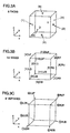
- FIGS. 3A, 3B and 3C show respective parts of the cell including the boundary data.
- the rectangular parallelepiped cell having the 6 boundary faces orthogonal to each other formed by the oct-tree division has 6 faces, 12 edges (ridgelines), and 8 vertexes.
- the face direction marks (face marks) L, R, D, U, B, and For (1), (2), (3), (4), (5) and (6) means “left”, “right”, “down”, “up”, “backward”, and “forward” when seeing in the positive direction of Z axis.
- the marks L, R, D, U, B, and F or (1), (2), (3), (4), (5) and (6) have higher priority.
- the marks LD, LU, LB, LF, RD, RU, RB, RF, DB, DF, UB, and UF of two face marks or [1] to [12] designate 12 edges, respectively. In this order [1] to [12], the edges have higher priority.
- LDB, LDF, LUB, LUF, RDB, RDF, RUB, and RUF of three face marks or 1 ⁇ to 8 ⁇ designate the vertexes, respectively. In this order 1 ⁇ to 8 ⁇ , the vertexes have higher priority.
- marks and numbers may be arbitrary, and other marks, numbers or the combination thereof suitable to logical computation may be used.
- FIGS. 4A through 4E designate the boundary cells having 3, 4, 5 and 6 cut points, respectively when the boundary surface included in the boundary data is a plane surface.
- the tracing is started from the cut point of an arbitrary edge, the neighboring edge is then searched for, and the cut point of the start edge is connected to the cut point of the neighboring edge.
- tracing is performed until the connection of the cut point returns to the cut point of the start edge.
- a closed loop (polygon) is formed by connecting the cut points.
- the edges neighboring each other always have one same face mark out of two face marks representing the edge.
- the cut points of the polygon are connected so that the polygon can be divided into a plurality of triangles.
- KTC4a and KTC4b there are two triangle dividing manners of dividing the polygon into plural (two) triangles, in the case of KTC5, there are 5 triangle dividing manners, and in the case of KTC6, there are 14 triangle dividing manners.
- the thus-evolved boundary cell type hereinbelow, referred to as evolved KTC
- the triangle division selecting step (F) it is necessary to select the triangle dividing manner that is the best approximation to the boundary data of the external data 12.
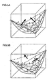
- FIGS. 5A and 5B are schematic illustrations respectively showing methods of selecting the triangle division selecting manner.
- FIG. 5A shows an example of the most optimum method
- FIG. 5B shows an example of an inadequate method.
- each of normal lines in normal line distribution on the input surface is extended to select one or more triangles on which the intersecting point with the extended normal line exists. Then, the triangle closest to the boundary surface part of the extended normal line is selected from the selected triangles in the cell to obtain an angle of the normal line of the selected triangle made with the extended normal line intersecting the triangle.
- These processes are performed for each of the normal lines in the in normal line distribution on the input surface.
- the triangle dividing manner in which the maximum angle deviation (difference) between the normal line of the triangle and the extended normal line intersecting the triangle becomes smallest is selected from the plural triangles.
- the normal line on the input surface is the normal line on each part formed by dividing a UV space by a specified number of divisions
- the normal line on the input surface is each normal line of the triangle meshes.
- FIGS. 6A and 6B show examples in the evolved KTC4a and KTC4b that can be applied to a curved surface having a large curvature.
- the boundary surface determination step (D) may be performed by the patter matching as follows.
- the boundary cells having 3, 4, and 5 cut points are classified into different boundary cell types KTC3, KTC4a, KTC4b, KTC5 and KTC6, respectively.
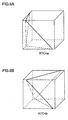
- FIGS. 7A and 7B show other examples of KTC5 and KTC6, respectively for reference.
- Each KTC has the following characteristics.
- the three edges contacting each other via a pivot vertex are always represented by the two face marks selected from the same three face marks.
- the respective edges represented by the cut two face marks always contacting (crossing) each other via the pivot vertex.
- the edges contacting each other via the pivot vertex LUF are LF, LU, and UF selected from LUF.
- each of 4 edges contacting each other via one edge is represented by the two face marks that are determined by selecting one face mark from the two face marks of the pivot edge and adding to the selected face mark one face mark of the face marks that are not included in the face marks of the pivot edge and are not included in the face marks of the edges opposite to the pivot edge.
- LU representing a pivot edge is decomposed into L and U.
- B and F each of which is not included in L and U representing the pivot edge and is not included in R and D representing the edge opposite to the pivot edge LU are each added to decomposed L and U to form LF, UF, LB and UB that represent 4 edges contacting each other via the pivot edge LU.
- 4 edges contacting each other via a pivot edge DF are represented by LD, RD, LF, RF, respectively.
- edges perpendicular to one face are represented by two face marks selected from the face marks that excludes the mark of the pivot face and the mark of the face opposite to the pivot face.
- 4 edges orthogonal to a pivot face L are represented by DB, DF, UB and UF that are the combination between one of D and U opposite to D and one of B and F opposite to B while excluding L and R opposite to L of the pivot face.
- a pivot vertex and a vertex opposite to the pivot vertex are selected so that the complement of KTC3 for the pivot vertex and KTC3 for the opposite vertex can be determined as 6 edges of KTC6 (complement of KTC3 and opposite KTC3 (12 - 3 - 3).
- LUB is also selected as the opposite vertex so that the complement of 3 edges of KTC3 for RDF and 3 edges of opposite KTC3 for LUB can be determined as 6 edges of KTC6.
- cut points on the complement edges of pivot vertex and the opposite vertex are connected.
- Loop formation is performed such that an arbitrary edge is selected (for example, RU), and next, the cut point of the edge contacting the selected edge (i.e., edge having the same mark R or U as RU) (in this example, RB or UF) is traced.
- an arbitrary edge for example, RU
- the cut point of the edge contacting the selected edge i.e., edge having the same mark R or U as RU
- RB or UF in this example, RB or UF
- Algorism of extracting a surface in a cell requires the reverse procedure of the above-described procedure.
- a boundary cell type extraction algorism in the boundary surface determination step (D) will be described.
- cut points substantially correspond to a vertex
- these cut points are considered as vertex shrinkage
- the vertex shrinkage is represented by KTC having 3 edges.
- cut target edges having cut points are sorted in the face direction order of LD to UF.
- edge combinations corresponding to respective pivot vertexes are (LD, LB, DB), (LD, LF, DF), (LU, LB, UB), (LU, LF, UF), (RD, RB, DB), (RD, RF, DF), (RU, RB, UB), and (RU, RF, UF) that correspond to vertexes 1 ⁇ to 8 ⁇ .
- vertex shrinkage where cut points are positioned at a vertex, it is checked whether or not the cut points can be classified into one of the combinations, and when the cut points can be classified, the vertex shrinkage is registered.
- edge combinations corresponding to respective pivot edges are (LB, LF, DB, DF), (LB, LF, UB, UF), (LD, LU, DB, UB), (LD, LU, DF, UF), (RB, RF, DB, DF), (RB, RF, UB, UF), (RD, RU, DB, UB), (RD, RU, DF, UF), (LD, LB, RD, RB), (LD, LF, RD, RF), (LU, LB, RU, RB), and (LU, LF, RU, RF).
- edge combinations are previously set, and when 4 cut points (4 edges) are obtained, the pattern matching is performed to determine the boundary cell type and the edge combination. In the case of vertex shrinkage, three edges are checked in the same manner as KTC3.
- KTC4b As shown in the following Table 3, the pattern matching is performed for 3 combinations of (DB, DF, UB, UF), (LB, LF, RB, RF), and (LD, LU, RD, RU).
- KTC4b (1) L (2) R (3) D (4) U (5)
- KTC5 As shown in the following Table 4, there are 24 (6 X 4) combinations that correspond to combinations between a pivot face and a pivot vertex existing on the pivot face. In the case of vertex shrinkage, three edges are checked in the same manner as KTC3.
- KTC6 As shown in the following Table 5, the pattern matching is performed for 4 edge combinations of a pivot vertex and the opposite vertex.
- KTC6 1 ⁇ LDB 7 ⁇ RUF 3 ⁇ LUB 6 ⁇ RDF 4 ⁇ LUF 5 ⁇ RDB 2 ⁇ LDF 7 ⁇ RUB LU,UB,RB, RD,DF,LF LD,LF,UF, RU,RB,DB LD,LB,UB, RU,RF,DF LU,LB,DB, RD,RF,UF
- FIGS. 8A through 8E show examples of boundary cells having 3, 4, 5 and 6 cut points, respectively when a boundary surface of boundary data is a curved surface.
- the boundary cells having 3, 4, 5 and 6 cut points, respectively are classified into evolved boundary surface types KTC3, KTC4a, KTC4b, KTC5, and KTC6, respectively.
- FIGS. 9A through 9F show examples of boundary cells having 7, 8, 9, 10, 11 and 12 cut points, respectively when the boundary surface consists of plane faces or the boundary surface is a curved surface.
- the above described method of forming a closed loop in the boundary surface determination step (D) can also be applied to the case where the number of cut points is 7, 8, 9, 10, 11 or 12.
- the oct-tree division step (A) and the cell classification step (B) it becomes possible to store, with a small memory capacity, external data 12 having cell hierarchical configuration that is formed by dividing the external data 12 of a target object into rectangular parallelepiped cells 13 having boundary planes orthogonal to each other.
- cells having 3, 4, 5, and 6 cut points are classified into different boundary cell types KTC3, KTC4a, KTC4b, KTC5 and KTC6, respectively.
- Combinations of edges (ridgelines) to be cut are previously set for each boundary surface type, and the boundary surface type and the edge combination are determined based on obtained cut points and cut edges by the pattern matching.
- the number of cut points is no fewer than 3 and no more than 12, the cut points may be traced and connected to form a closed loop. Therefore, according to the embodiment of the present invention, it is possible to store the boundary surface with the boundary cell type and the edge combination. Further, the data can be stored with a small memory capacity, and neighboring cell continuity can be held.
- the polygon formed by the cut points is divided into a plurality of triangles that are formed by connecting the cut points. Then, each of the normal lines included in the boundary data of the external data 12 is extended, and the triangle that has the intersection point with the extended normal line and has the least distance from boundary surface part of the extended normal line is selected. Next, the angle made between the normal line of the selected triangle and the extended normal line is obtained. These processes are performed for each extended normal line. Thereafter, one triangle division manner in which the maximum angle deviation (difference) between the normal line of the triangle and the extended normal line becomes smallest is selected from a plurality of triangle dividing manners. In this manner, even when a boundary surface is a curved surface, it is possible to maintain the neighboring cell continuity and form the divided triangle meshes that can approximate the curved surface without generating a gap and a sharp angle between the triangles.
- the data converting method and program of converting three-dimensional shape data into cell internal data have the following advantage. That is, for volume CAD, with the neighboring cell continuity being maintained, without generating a gap or forming an inaccurate triangle, it is possible to configure, from the external data, the cell internal data of which boundary surface can be divided into the triangle meshes that approximate even a curved surface having a large curvature with high accuracy.
Abstract
Description
- The present invention relates to a storing method of storing, with a small memory capacity, substantial data that is configured by integrating shape data and physical property data so that CAD and simulation can be integrated. Specifically, the present invention relates to a method and program of converting three-dimensional shape data into internal data of a cell by oct-tree division.
- In the field of leading-edge research and technology development, as the research and technology is highly developed and complicated, it becomes inevitable to perform a process of trial and error many times, so that a risk of failure in the development process is raised. In order to lead in science and technology, it is very important to avoid such a risk as much as possible, and to make innovative advancement and efficiency promotion.
- At present, in the field of research and technology development, CAD (Computer Aided Design), CAM (Computer Aided Manufacturing), CAE (Computer Aided Engineering), CAT (Computer Aided Testing) are used as simulation means for designing, processing, analyzing, and testing, respectively.
- Further, the C-Simulation (Corporative Simulation) that is successive simulation, A-CAM (Advanced CAM) that takes processing into account, and D-fabrication (Deterministic Fabrication) that achieves ultimate accuracy will become widespread by the present invention.
- When using the above-mentioned simulation means, data of a target object is stored by CSG (Constructive Solid Geometry) or B-rep (Boundary Representation).
- However, in the case of CSG, an entire target object is stored as an aggregation of minute solid models. Accordingly, the data amount becomes large, and simulation means (software, for example) handles a large amount of data. Therefore, there is a problem in that even a large computer takes much time to perform data analyzing.
- In the case of B-rep, since the target object is represented by the boundary, the data amount becomes small. However, the information about the inside of the boundary surface cannot be obtained directly, and there is a problem in that the data itself is not suitable to deforming analysis.
- Furthermore, according to the above-mentioned conventional data storing means, each time heat/fluid analysis, largely deforming analysis of a solid, or coupled analysis of them is performed, the data is divided into meshes suitable to the analysis, and a finite element method or the like is used. The result of the analysis can be displayed, for example, but it is difficult to integrate CAD and simulation. Accordingly, there is a problem in that respective processes of designing, analyzing, processing, assembling, testing, and so on cannot be managed by using the same data.
- In other words, the conventional Solid/Surface-CAD (hereinbelow, referred to as S-CAD) has the following problems.
- (1) The data communication, and internal converting operation of the data are poor (that is, there is a problem of a numerical value error and a process method).
- (2) The data cannot be applied directly to the simulation (that is, since the data does not include the internal data, the meshes need to be generated).
- (3) It is not possible to consider how to perform the processing by CAM (there is only a final shape).
-
- Further, there are the following problems regarding the processing.
- (1) It is not possible to represent the processing (the aid of rough processing and aid of process designing are inadequate).
- (2) The data cannot cope with a new processing method such as laser processing and ultra front edge processing (that is, other processing except cutting processing cannot be performed, and numerical value accuracy is inadequate).
- (3) A processing method cannot be selected when a target object is a complex having different material properties inside.
-
- In order to solve the above problems, prior to the present patent application, the inventor(s) of the present invention made the invention "Method of Storing Substantial Data Configured by Integrating Shape Data and Physical Property Data" that was filed as Japanese patent application No. 2001-25023).
- According to this prior invention, as schematically shown in FIG. 1, external data including boundary data of a target object is divided into rectangular parallelepiped cells by oct-tree division. Each of rectangular parallelepiped cells has boundary faces orthogonal to each other. Then, each cell is classified into an
internal cell 13a positioned inside or outside the target object or aboundary cell 13b including a boundary face. In FIG. 1, thereference numeral 15 designates a cut point. - With this prior invention, various physical property values are stored in respective cells so that the integrated substantial data of the shape data and the physical property data can be stored by using a small memory capacity. Thereby, it is possible to achieve integral management of shape data, structure data, physical property data, and history of a target object. Accordingly, data about a series of processes including designing, processing, assembling, testing, evaluating, and the like can be managed by the same data, and CAD and simulation can be integrated.
- In the case of this storing method (hereinbelow, referred to as "volume CAD" or "V-CAD") of storing substantial data, the boundary data for restructuring the boundary surface of the three-dimensional shape data (external data) needs to be held in the boundary cell.
- If the boundary data cannot maintain continuity with the neighboring cells, when the surface of the cell is divided into triangle-shaped meshes, a gap (crack), a minute triangle, or a thin long triangle is generated. Therefore, a problem arises in that accurate simulation cannot be performed.
- Meanwhile, there is a known method (crack patch method) of filling up a gap between the triangle meshes that is generated between different size volumes. However, in this method, the gap is simply filled up so that the triangle meshes sharing the edge thereof and making a sharp angle therebetween are generated at the position where the original surface is smooth. In order to solve this problem, Japanese Laid-Open Patent Publication No. 2001-22961 proposes "Method of Generating Same Phase Surface from Non-Uniformity Volume Model". However, in this method, application of different model volume CAD is difficult, and the process of this method is complicated.
- It is an object of the present invention to provide a data converting method and program by which for volume CAD, with the neighboring cell continuity being maintained, without generating a gap or forming an inaccurate triangle, it is possible to configure, from the external data, the cell internal data of which boundary surface can be divided into the triangle meshes that approximate even a curved surface having a large curvature with high accuracy.
- According to the present invention, there is provided a method and program of converting three-dimensional shape data into cell internal data, comprising: an oct-tree division step of dividing external data including boundary data of a target object into rectangular parallelepiped cells having boundary planes orthogonal to each other by oct-tree division; a cell classification step of classifying each of the cells into an internal cell positioned inside or outside the target object or a boundary cell including the boundary data; a cut point determination step of determining cut points of edges of the boundary cell based on the boundary data; and a boundary surface determination step of connecting cut points to form a polygon, and determining the polygon as the cell internal data when the number of the determined cut points is no fewer than 3 and no more than 12.
- By the method and program, it is possible to store, with a small memory capacity, the external data as hierarchical configuration of the cells that are formed by the oct-tree division of the external data and that have boundary faces orthogonal to each other.
- Furthermore, by the cut point determination step and the boundary surface determination step, it is possible to obtain the cell internal data as the polygon with the neighboring cell continuity being maintained, without generating a gap or a deformed triangle.
- According to one aspect of the preset invention, the boundary cells having 3, 4, 5 and 6 cut points, respectively are classified into different boundary cell types, respectively. Combinations of edges to be cut are previously set for each of the boundary cell types. The boundary cell type for the boundary cell is determined based on the determined cut points and cut edges by pattern matching. Thereby, it is possible to store the boundary surface by using the boundary cell type and the edge combination. Accordingly, it is possible to store the boundary surface with a small memory capacity while maintaining the neighboring cell continuity.
- According to another aspect of the present invention, in the boundary surface determination step, tracing is performed only on the faces of the boundary cell through the cut points to form a closed loop as the polygon. Thereby, the boundary surface can be stored with triangles represented by the cut points.
- Preferably, the method and the program further comprises; a triangle division step of dividing the polygon into a plurality of triangles by connecting the cut points, in one or more dividing manners; and a triangle division selecting step of extending each of normal lines included in the external data, selecting from the plurality of triangles, the triangle that has an intersecting point with the each extended normal line and has the least distance from boundary surface part of the each extended normal line, obtaining an angle made between a normal line of the selected triangle and the each extended normal line, and selecting the dividing manner in which a maximum angle difference between the normal line of the triangle and the extended normal line is smallest.
- Thereby, even when a boundary surface is a curved surface, it is possible to maintain the neighboring cell continuity and form the divided triangle meshes that can approximate the curved surface without generating a gap and inaccurate triangle.
- Other objects, features, and advantages of the present invention will become apparent from the following the detailed description with reference to the drawings.
-
- FIG. 1 is a schematic illustration two-dimensionally showing a dividing method according to the present invention;
- FIG. 2 is a flowchart showing a data converting method and program according to an embodiment of the present invention;
- FIGS. 3A through 3C show respective parts of a boundary cell including boundary data according to the embodiment of the present invention;
- FIGS. 4A through 4E show examples of boundary cells having 3, 4, 5, and 6 cut points, respectively according to the embodiment of the present invention;
- FIGS. 5A and 5B are schematic illustrations showing a method of selecting triangle dividing manner according to the embodiment of the present invention;
- FIGS. 6A and 6B show examples of evolved KTC4a and KTC4b for a curved surface having a large curvature according to the embodiment of the present invention;
- FIGS. 7A and 7B show other examples of KTC5 and KTC6 according to the embodiment of the present invention;
- FIGS. 8A through 8E show examples of boundary cells having 3, 4, 5 and 6 cut points, respectively when boundary surfaces are curved surfaces according to the embodiment of the present invention; and
- FIGS. 9A through 9F show examples of boundary cells having 7, 8, 9, 10, 11 and 12, respectively according to the embodiment of the present invention.
-
- In the following, a preferred embodiment of the present invention will be described with reference to the drawings.
- FIG. 2 is a flowchart of a data converting method and data converting program according to the embodiment of the present invention. As shown in FIG. 2, the data converting method according to the embodiment includes an oct-tree division step (A), a cell classification step (B), a cut point determination step (C), a boundary surface determination step (D), and a triangle division step (E), and a triangle division selecting step (F). Similar to the data converting method, the data converting program according to the embodiment includes an oct-tree division program code (A), a cell classification program code (B), a cut point determination program code (C), a boundary surface determination program code (D), and a triangle division program code (E), and a triangle division selecting program code (F). The following description is mainly directed to the data converting method. However, the data converting program has the same function as the data converting method.
-
External data 12 input from the outside is polygon data representing a polyhedron, a tetrahedron element data or hexahedron element data used for a finite element method, curved surface data used for three-dimensional CAD or a CG tool, or data that represents other three-dimensional shape by using information configured by a partial plane and curved surfaces. - The
external data 12 is not limited to such data (referred to as S-CAD data), and may be (1) data that a person inputs and creates by a V-CAD interface (V-interface), (2) surface digitized data formed by a measuring device, sensor, or digitizer, or (3) volume data including internal information such as voxel data that is used for volume rendering, CT scan or MRI. - In the oct-tree division step (A), the
external data 12 that is obtained by an external data obtaining step (not shown in the drawing) and includes boundary data of the target object is divided, by the oct-tree division, intorectangular parallelepiped cells 13 each of which has boundary faces orthogonal to each other. Specifically, in this oct-tree division step (A), space division is performed by modified oct-tree division. In oct-tree representation, i.e., in the space division by the oct-tree division, a standardrectangular parallelepiped 13 including (at least a part of) a target three-dimensional object is divided into eight parallelepipeds, and this division is repeatedly performed until the divided rectangular parallelepiped is completely included in or excluded from each region. By performing this oct-tree division, it is possible to greatly decrease data amount compared to the voxel data representation. - One divided space region that is formed by the oct-tree space division is referred to as a
cell 13. Thecell 13 is a rectangular parallelepiped having boundary faces orthogonal to each other. One region existing in the space is represented by cell hierarchical configuration, the number of divisions, or resolution. In this manner, the target object is represented as the cells having different sizes that are put on top of each other in the entire space. - The special case of oct-tree division representation where all of the representing cells are congruent rectangular parallelepipeds (having the same number of divisions) is the same as the voxel representation.
- In the cell classification step (B), each divided
cell 13 is classified into aninternal cell 13a positioned inside or outside the target object or aboundary cell 13b including the boundary data. - That is, according to the embodiment of the present invention, the modified oct-tree division is used to represent the
boundary cell 13b. In addition, theinternal cell 13a (rectangular parallelepiped) is the maximum size cell that does not contain the boundary of the target object, and theboundary cell 13b is the cell that includes the boundary information of theexternal data 12. - In the cut point determination step (C), the cut points 15 of the edges of the
boundary cell 13b are determined based on the boundary data. - In the boundary surface determination step (D), when the number of the determined cut points is no fewer than 3 and no more than 12, the polygon formed by connecting the cut points is determined as the cell internal data of the boundary surface. That is, in the boundary surface determination step (D), the polygon is a closed loop that is formed by tracing on only the cell surface through the cut points of the edges (the polygon is not always included in one plane as shown in FIG. 8D, for example). Alternatively, the
boundary cells 13b having 3, 4, 5 and 6 cut points are respectively classified into different boundary cell types (KTC3, KTC4a, KTC4b, KTC5, KTC6). Combinations of the edges to be cut are previously set for each boundary cell type, and the boundary cell type and the edge combination can be determined by pattern matching based on the determined number of cut points and the cut edges. - In the triangle division step (E), the polygon determined in the boundary surface determination step (D) is divided into a plurality of triangles by connecting cut points, as shown in FIGS. 8B through 8E. Mostly, there are a plurality of triangle dividing manners (i.e., cut point connecting manners).
- In the triangle division selecting step (F), each normal line included in the boundary data of the
external data 12 is extended, and each of the triangles that has the intersecting point with the extended normal line and has the least distance from the boundary surface part of this normal line is selected. Then, an angle made between the normal line of each selected triangle and the extended normal line is calculated. These processes are performed for each of the triangle dividing manners. Thereafter, the triangle dividing manner in which the maximum angle difference between the normal line of the triangle and the extended normal line becomes smallest is selected from a plurality of the triangle dividing manner. - According to the data converting method of this embodiment, the steps (A) through (F) are repeatedly performed in accordance with necessity. By using the thus-obtained V-CAD data, simulations such as designing, analyzing, processing, assembling, and testing are successively performed. Then, in an output step, the result of the simulation is output as triangle patching data such as CAM or polygon data.
- In the following, the embodiment of the present invention will be described in detailed.
- The
external data 12 including the boundary data of the target object is assumed to be a curved surface or triangle patch (nets or meshes), (hereinbelow, referred to as an input surface). The following description is directed to the data converting method in which the boundary cell types KTC3, KTC4a, KTC4b, KTC5, and KTC6 that are the internal representation types of the volume CAD are formed by converting the information only about the normal lines of the input surface and cut points of the edges of each boundary cell formed by the space division (voxel or oct-tree division). The boundary cell type KTC3, KTC4a, KTC4b, KTC5, or KTC6 is called KT cell or KTC for short. - FIGS. 3A, 3B and 3C show respective parts of the cell including the boundary data. The rectangular parallelepiped cell having the 6 boundary faces orthogonal to each other formed by the oct-tree division has 6 faces, 12 edges (ridgelines), and 8 vertexes.
- In FIG. 3A, the face direction marks (face marks) L, R, D, U, B, and For (1), (2), (3), (4), (5) and (6) means "left", "right", "down", "up", "backward", and "forward" when seeing in the positive direction of Z axis. In this order, the marks L, R, D, U, B, and F or (1), (2), (3), (4), (5) and (6) have higher priority.
- As shown in FIG. 3B, the marks LD, LU, LB, LF, RD, RU, RB, RF, DB, DF, UB, and UF of two face marks or [1] to [12] designate 12 edges, respectively. In this order [1] to [12], the edges have higher priority.
- As shown in FIG. 3C, LDB, LDF, LUB, LUF, RDB, RDF, RUB, and RUF of three face marks or 1 ○ to 8 ○ designate the vertexes, respectively. In this
order 1 ○ to 8 ○, the vertexes have higher priority. - These marks and numbers may be arbitrary, and other marks, numbers or the combination thereof suitable to logical computation may be used.
- In the following, the marks of the cut edges in KTC shown in FIGS. 3A through 3C are used as the reference marks for the edges.
- FIGS. 4A through 4E designate the boundary cells having 3, 4, 5 and 6 cut points, respectively when the boundary surface included in the boundary data is a plane surface. The tracing is started from the cut point of an arbitrary edge, the neighboring edge is then searched for, and the cut point of the start edge is connected to the cut point of the neighboring edge. Thus, tracing is performed until the connection of the cut point returns to the cut point of the start edge. In this manner, a closed loop (polygon) is formed by connecting the cut points. The edges neighboring each other always have one same face mark out of two face marks representing the edge.
- In the triangle division step (E), the cut points of the polygon are connected so that the polygon can be divided into a plurality of triangles. In most cases, there are a plurality of triangle dividing manners in which the polygon is divided into a plurality of triangles. Specifically, in the case of KTC4a and KTC4b, there are two triangle dividing manners of dividing the polygon into plural (two) triangles, in the case of KTC5, there are 5 triangle dividing manners, and in the case of KTC6, there are 14 triangle dividing manners. The thus-evolved boundary cell type (hereinbelow, referred to as evolved KTC) results in the different shape depending on the triangle dividing manner. Accordingly, in the triangle division selecting step (F), it is necessary to select the triangle dividing manner that is the best approximation to the boundary data of the
external data 12. - FIGS. 5A and 5B are schematic illustrations respectively showing methods of selecting the triangle division selecting manner. FIG. 5A shows an example of the most optimum method, and FIG. 5B shows an example of an inadequate method. According to the embodiment of the present invention, each of normal lines in normal line distribution on the input surface is extended to select one or more triangles on which the intersecting point with the extended normal line exists. Then, the triangle closest to the boundary surface part of the extended normal line is selected from the selected triangles in the cell to obtain an angle of the normal line of the selected triangle made with the extended normal line intersecting the triangle. These processes are performed for each of the normal lines in the in normal line distribution on the input surface. Then, the triangle dividing manner in which the maximum angle deviation (difference) between the normal line of the triangle and the extended normal line intersecting the triangle becomes smallest is selected from the plural triangles.
- In the case where the input surface is a parametric surface, the normal line on the input surface is the normal line on each part formed by dividing a UV space by a specified number of divisions, and in the case where the input surface is data of triangle meshes, the normal line on the input surface is each normal line of the triangle meshes.
- FIGS. 6A and 6B show examples in the evolved KTC4a and KTC4b that can be applied to a curved surface having a large curvature.
- Different from the above-described examples, when the number of cut points is no fewer than 3 and no more than 6, the boundary surface determination step (D) may be performed by the patter matching as follows.
- In this embodiment of the present invention,
The boundary cells having 3, 4, and 5 cut points are classified into different boundary cell types KTC3, KTC4a, KTC4b, KTC5 and KTC6, respectively. FIGS. 7A and 7B show other examples of KTC5 and KTC6, respectively for reference. - Each KTC has the following characteristics.
- In the case of KTC3, the three edges contacting each other via a pivot vertex are always represented by the two face marks selected from the same three face marks. In other words, when the three face marks representing one pivot vertex are cut into two face marks, the respective edges represented by the cut two face marks always contacting (crossing) each other via the pivot vertex. For example, the edges contacting each other via the pivot vertex LUF are LF, LU, and UF selected from LUF.
- In the case of KTC4a, each of 4 edges contacting each other via one edge (called pivot edge) is represented by the two face marks that are determined by selecting one face mark from the two face marks of the pivot edge and adding to the selected face mark one face mark of the face marks that are not included in the face marks of the pivot edge and are not included in the face marks of the edges opposite to the pivot edge. For example, LU representing a pivot edge is decomposed into L and U. Then, B and F each of which is not included in L and U representing the pivot edge and is not included in R and D representing the edge opposite to the pivot edge LU are each added to decomposed L and U to form LF, UF, LB and UB that represent 4 edges contacting each other via the pivot edge LU. In the same manner, 4 edges contacting each other via a pivot edge DF are represented by LD, RD, LF, RF, respectively.
- In the case of KTC4b, 4 edges perpendicular to one face (pivot face) are represented by two face marks selected from the face marks that excludes the mark of the pivot face and the mark of the face opposite to the pivot face. For example, 4 edges orthogonal to a pivot face L are represented by DB, DF, UB and UF that are the combination between one of D and U opposite to D and one of B and F opposite to B while excluding L and R opposite to L of the pivot face.
- In the case of KTC5, when selecting a pivot surface and a pivot vertex on the pivot surface (KTC4b + KTC3) , 4 edges are created in the same manner as the KTC4b, and the operation of "4 created
edges XOR 3 edges contacting each other via the pivot vertex" is performed (union set minus product set). For example, when a pivot face is B, and a pivot vertex is RDB, the operation of "(LD, LU, RD, RU) (for the pivot face B) XOR (RD, DB, RB) (for the pivot vertex RDB) results in (LD, LU, RU, DB, RB). - In the case of KTC6, a pivot vertex and a vertex opposite to the pivot vertex are selected so that the complement of KTC3 for the pivot vertex and KTC3 for the opposite vertex can be determined as 6 edges of KTC6 (complement of KTC3 and opposite KTC3 (12 - 3 - 3). For example, when selecting RDF as a pivot vertex, LUB is also selected as the opposite vertex so that the complement of 3 edges of KTC3 for RDF and 3 edges of opposite KTC3 for LUB can be determined as 6 edges of KTC6. In other words, in the case of KTC6, cut points on the complement edges of pivot vertex and the opposite vertex are connected. Loop formation is performed such that an arbitrary edge is selected (for example, RU), and next, the cut point of the edge contacting the selected edge (i.e., edge having the same mark R or U as RU) (in this example, RB or UF) is traced.
- Algorism of extracting a surface in a cell requires the reverse procedure of the above-described procedure. In the following, a boundary cell type extraction algorism in the boundary surface determination step (D) will be described.
- When cut points substantially correspond to a vertex, these cut points are considered as vertex shrinkage, and the vertex shrinkage is represented by KTC having 3 edges. In a preliminary process, cut target edges having cut points are sorted in the face direction order of LD to UF.
- Next, a reverse KTC rule (KTC pattern is determined from cut points) will be described.
- In the case of KTC3, as shown in the following Table 1, edge combinations corresponding to respective pivot vertexes are (LD, LB, DB), (LD, LF, DF), (LU, LB, UB), (LU, LF, UF), (RD, RB, DB), (RD, RF, DF), (RU, RB, UB), and (RU, RF, UF) that correspond to
vertexes 1 ○ to 8 ○. In the case of the vertex shrinkage where cut points are positioned at a vertex, it is checked whether or not the cut points can be classified into one of the combinations, and when the cut points can be classified, the vertex shrinkage is registered. Then, regarding the neighboring cells, the cell of the vertex shrinkage is copied to maintain the consistency or continuity.KTC3 1 ○ LDB 2 ○ LDF 3 ○ LUB 4 ○ LUF 5 ○ RDB 6 ○ RDF 7 ○ RUB 8 ○RUF LD, LD, LU, LU, RD, RD, RU, RU, LB, LF, LB, LF, RB, RF, RB, RF, DB DF UB UF DB DF UB UF - In the case of KTC4a, there are 12 combinations of 4 edges corresponding to each pivot edge. As shown in the following Table 2, edge combinations corresponding to respective pivot edges are (LB, LF, DB, DF), (LB, LF, UB, UF), (LD, LU, DB, UB), (LD, LU, DF, UF), (RB, RF, DB, DF), (RB, RF, UB, UF), (RD, RU, DB, UB), (RD, RU, DF, UF), (LD, LB, RD, RB), (LD, LF, RD, RF), (LU, LB, RU, RB), and (LU, LF, RU, RF). These edge combinations are previously set, and when 4 cut points (4 edges) are obtained, the pattern matching is performed to determine the boundary cell type and the edge combination. In the case of vertex shrinkage, three edges are checked in the same manner as KTC3.

- In the case of KTC4b, as shown in the following Table 3, the pattern matching is performed for 3 combinations of (DB, DF, UB, UF), (LB, LF, RB, RF), and (LD, LU, RD, RU).
KTC4b (1) L
(2) R(3) D
(4) U(5) B
(6) FDB,DF,UB,UF LB,LF,RB,RF LD,LU,RD,RU - In the case of KTC5, as shown in the following Table 4, there are 24 (6 X 4) combinations that correspond to combinations between a pivot face and a pivot vertex existing on the pivot face. In the case of vertex shrinkage, three edges are checked in the same manner as KTC3.
KTC5 (1) L 1 ○ LDB 2 ○ LDF 3 ○ LUB 4 ○LUF DF,UB,UF,
LD,LBDB,UB,UF,
LD,LFDB,DF,UF,
UD,LBDB,DF,UB,
LU,LF(2) R 5 ○ RDB 6 ○ RDF 7 ○ RUB 8 ○RUF DF,UB,UF,
RD,RBDB,UB,UF,
RD,RFDB,DF,UF,
RU,RBDB,DF,UB,
RU,RF(3) D 1 ○ LDB 2 ○ LDF 5 ○ RDB 6 ○RDF LF,RB,RF,
LD,DBLB,RB,RF,
LD,DFLB,LF,RF,
RD,DBLB,LF,RB,
RD,DF(4) U 3 ○ LUB 4 ○ LUF 7 ○ RUB 8 ○RUF LF,RB,RF,
LU,UBLB,RB,RF,
LU,UFLB,LF,RF,
RU,UBLB,LF,RB,
RU,UF(5) B 1 ○ LDB 3 ○ LUB 5 ○ RDB 7 ○RUB LU,RD,RU,
LB,DBLD,RD,RU,
LB,UBLD,LU,RU,
RB,DBLD,LU,RD,
RB,UB(6) F 2 ○ LDF 4 ○ LUF 6 ○ RDF 8 ○RUF LU,RD,RU,
LF,DFLD,RD,RU,
LF,UFLD,LU,RU,
RF,DFLD,LU,RD,
RF,UF - In the case of KTC6, as shown in the following Table 5, the pattern matching is performed for 4 edge combinations of a pivot vertex and the opposite vertex.
KTC6 1 ○LDB
7 ○RUF 3 ○LUB
6 ○RDF 4 ○LUF
5 ○RDB 2 ○LDF
7 ○RUBLU,UB,RB,
RD,DF,LFLD,LF,UF,
RU,RB,DBLD,LB,UB,
RU,RF,DFLU,LB,DB,
RD,RF,UF - When there is a boundary cell that cannot be classified into the above boundary types KTC3 through KTC6, this boundary cell is left without classifying, or in accordance with necessity, the steps (A) through (F) are repeatedly performed.
- FIGS. 8A through 8E show examples of boundary cells having 3, 4, 5 and 6 cut points, respectively when a boundary surface of boundary data is a curved surface. According to the embodiment of the present invention, the boundary cells having 3, 4, 5 and 6 cut points, respectively are classified into evolved boundary surface types KTC3, KTC4a, KTC4b, KTC5, and KTC6, respectively.
- FIGS. 9A through 9F show examples of boundary cells having 7, 8, 9, 10, 11 and 12 cut points, respectively when the boundary surface consists of plane faces or the boundary surface is a curved surface.
- The above described method of forming a closed loop in the boundary surface determination step (D) can also be applied to the case where the number of cut points is 7, 8, 9, 10, 11 or 12.
- As described above, according to the data converting method of the embodiment of the present invention, by the oct-tree division step (A) and the cell classification step (B), it becomes possible to store, with a small memory capacity,
external data 12 having cell hierarchical configuration that is formed by dividing theexternal data 12 of a target object intorectangular parallelepiped cells 13 having boundary planes orthogonal to each other. - Furthermore, cells having 3, 4, 5, and 6 cut points are classified into different boundary cell types KTC3, KTC4a, KTC4b, KTC5 and KTC6, respectively. Combinations of edges (ridgelines) to be cut are previously set for each boundary surface type, and the boundary surface type and the edge combination are determined based on obtained cut points and cut edges by the pattern matching. Alternatively, when the number of cut points is no fewer than 3 and no more than 12, the cut points may be traced and connected to form a closed loop. Therefore, according to the embodiment of the present invention, it is possible to store the boundary surface with the boundary cell type and the edge combination. Further, the data can be stored with a small memory capacity, and neighboring cell continuity can be held.
- Furthermore, the polygon formed by the cut points is divided into a plurality of triangles that are formed by connecting the cut points. Then, each of the normal lines included in the boundary data of the
external data 12 is extended, and the triangle that has the intersection point with the extended normal line and has the least distance from boundary surface part of the extended normal line is selected. Next, the angle made between the normal line of the selected triangle and the extended normal line is obtained. These processes are performed for each extended normal line. Thereafter, one triangle division manner in which the maximum angle deviation (difference) between the normal line of the triangle and the extended normal line becomes smallest is selected from a plurality of triangle dividing manners. In this manner, even when a boundary surface is a curved surface, it is possible to maintain the neighboring cell continuity and form the divided triangle meshes that can approximate the curved surface without generating a gap and a sharp angle between the triangles. - Thus, the data converting method and program of converting three-dimensional shape data into cell internal data have the following advantage. That is, for volume CAD, with the neighboring cell continuity being maintained, without generating a gap or forming an inaccurate triangle, it is possible to configure, from the external data, the cell internal data of which boundary surface can be divided into the triangle meshes that approximate even a curved surface having a large curvature with high accuracy.
- The preferred embodiment of the present invention including several examples is described in the above. However, the present invention is not limited to this embodiment, and various improvements, modifications, and equivalents can be made without departing from scope of the present invention.
Claims (5)
- A method of converting three-dimensional shape data into cell internal data, comprising:an oct-tree division step of dividing external data including boundary data of a target object into rectangular parallelepiped cells having boundary planes orthogonal to each other by oct-tree division;a cell classification step of classifying each of the cells into an internal cell positioned inside or outside the target object or a boundary cell including the boundary data;a cut point determination step of determining cut points of edges of the boundary cell based on the boundary data; anda boundary surface determination step of connecting cut points to form a polygon, and determining the polygon as the cell internal data when the number of the determined cut points is no fewer than 3 and no more than 12.
- The method according to claim 1, wherein in the boundary surface determination step, the boundary cells having 3, 4, 5 and 6 cut points, respectively are classified into different boundary cell types, respectively,
combinations of edges to be cut are previously set for each of the boundary cell types, and
the boundary cell type for the boundary cell is determined based on the determined cut points and cut edges by pattern matching. - The method according to claim 1, wherein in the boundary surface determination step, tracing is performed only on the faces of the boundary cell through the cut points to form a closed loop as the polygon.
- The method according to claim 1, 2 or 3, further comprising;
a triangle division step of dividing the polygon into a plurality of triangles by connecting the cut points, in one or more dividing manners; and
a triangle division selecting step of extending each of normal lines included in the external data, selecting from the plurality of triangles, the triangle that has an intersecting point with the each extended normal line and has the least distance from boundary surface part of the each extended normal line, obtaining an angle made between a normal line of the selected triangle and the each extended normal line, and selecting the dividing manner in which a maximum angle difference between the normal line of the triangle and the extended normal line is smallest. - A program of converting three-dimensional shape data into cell internal data, comprising:an oct-tree division program code of dividing external data including boundary data of a target object into rectangular parallelepiped cells having boundary planes orthogonal to each other by oct-tree division;a cell classification program code of classifying each of the cells into an internal cell positioned inside or outside the target object or a boundary cell including the boundary data;a cut point determination program code of determining cut points of edges of the boundary cell based on the boundary data; anda boundary surface determination program code of connecting cut points to form a polygon, and determining the polygon as the cell internal data when the number of the determined cut points is no fewer than 3 and no more than 12.
Applications Claiming Priority (3)
| Application Number | Priority Date | Filing Date | Title |
|---|---|---|---|
| JP2001370040 | 2001-12-04 | ||
| JP2001370040 | 2001-12-04 | ||
| PCT/JP2002/012629 WO2003048980A1 (en) | 2001-12-04 | 2002-12-03 | Method for converting 3-dimensional shape data into cell inner data and conversion program |
Publications (2)
| Publication Number | Publication Date |
|---|---|
| EP1452984A1 true EP1452984A1 (en) | 2004-09-01 |
| EP1452984A4 EP1452984A4 (en) | 2013-05-01 |
Family
ID=19179335
Family Applications (1)
| Application Number | Title | Priority Date | Filing Date |
|---|---|---|---|
| EP02786014.7A Withdrawn EP1452984A4 (en) | 2001-12-04 | 2002-12-03 | Method for converting 3-dimensional shape data into cell inner data and conversion program |
Country Status (5)
| Country | Link |
|---|---|
| US (1) | US7333104B2 (en) |
| EP (1) | EP1452984A4 (en) |
| JP (1) | JP4255016B2 (en) |
| CN (1) | CN1311390C (en) |
| WO (1) | WO2003048980A1 (en) |
Cited By (2)
| Publication number | Priority date | Publication date | Assignee | Title |
|---|---|---|---|---|
| EP1507220A1 (en) * | 2002-05-17 | 2005-02-16 | Riken | Boundary data inside/outside judgment method and program thereof |
| EP1978487A3 (en) * | 2007-04-06 | 2011-01-05 | Hitachi, Ltd. | Numerical analysis mesh generating method and apparatus |
Families Citing this family (11)
| Publication number | Priority date | Publication date | Assignee | Title |
|---|---|---|---|---|
| JP4381743B2 (en) | 2003-07-16 | 2009-12-09 | 独立行政法人理化学研究所 | Method and program for generating volume data from boundary representation data |
| US7234122B2 (en) * | 2004-04-19 | 2007-06-19 | Lsi Corporation | Three-dimensional interconnect resistance extraction using variational method |
| JP4526063B2 (en) | 2004-05-06 | 2010-08-18 | 独立行政法人理化学研究所 | Volume data cell labeling method and program, and volume data cell labeling device |
| JP4605772B2 (en) * | 2005-03-09 | 2011-01-05 | 独立行政法人理化学研究所 | Generation method of boundary surface information, generation program thereof, and generation system thereof |
| JP4783100B2 (en) | 2005-09-12 | 2011-09-28 | 独立行政法人理化学研究所 | Method of converting boundary data into in-cell shape data and its conversion program |
| JP6351138B2 (en) * | 2013-03-13 | 2018-07-04 | 国立大学法人 筑波大学 | Diagnostic imaging support program |
| EP2829993B1 (en) * | 2013-07-25 | 2020-09-30 | Dassault Systèmes | Design of a path connecting a first point to a second point in a three-dimensional scene |
| JP2017503244A (en) * | 2013-11-26 | 2017-01-26 | フォヴィア インコーポレイテッドFovia,Inc | Method and system for volume rendering color mapping on polygonal objects |
| CN104732589B (en) * | 2015-04-14 | 2017-06-13 | 中国航天空气动力技术研究院 | Quick hybrid grid generation method |
| WO2018070993A1 (en) * | 2016-10-11 | 2018-04-19 | Hewlett-Packard Development Company, L.P. | Generating data for a three-dimensional (3d) printable object |
| US10353352B2 (en) * | 2017-02-22 | 2019-07-16 | Mitsubishi Electric Research Laboratories, Inc. | System and method for distributed machining simulation |
Citations (1)
| Publication number | Priority date | Publication date | Assignee | Title |
|---|---|---|---|---|
| US5517602A (en) * | 1992-12-03 | 1996-05-14 | Hewlett-Packard Company | Method and apparatus for generating a topologically consistent visual representation of a three dimensional surface |
Family Cites Families (54)
| Publication number | Priority date | Publication date | Assignee | Title |
|---|---|---|---|---|
| DE2547477C3 (en) | 1975-10-23 | 1981-01-22 | Maschinenfabrik Rissen Gmbh, 2000 Hamburg | Method and device for deep-drawing a film made of thermoplastic material |
| US4694404A (en) * | 1984-01-12 | 1987-09-15 | Key Bank N.A. | High-speed image generation of complex solid objects using octree encoding |
| US4665192A (en) | 1984-03-19 | 1987-05-12 | The Rockefeller University | 2-(2-furoyl)-4(5)-2(furanyl)-1H-imidazole |
| US4665492A (en) | 1984-07-02 | 1987-05-12 | Masters William E | Computer automated manufacturing process and system |
| US4729098A (en) | 1985-06-05 | 1988-03-01 | General Electric Company | System and method employing nonlinear interpolation for the display of surface structures contained within the interior region of a solid body |
| US4710876A (en) | 1985-06-05 | 1987-12-01 | General Electric Company | System and method for the display of surface structures contained within the interior region of a solid body |
| US4719585A (en) | 1985-08-28 | 1988-01-12 | General Electric Company | Dividing cubes system and method for the display of surface structures contained within the interior region of a solid body |
| US5197013A (en) | 1987-07-28 | 1993-03-23 | David M. Dundorf | Method of forming a carved sign using an axially rotating carving tool |
| JPH0767576B2 (en) | 1987-11-18 | 1995-07-26 | ファナック株式会社 | Hole position definition method for punch mounting parts |
| JP2920195B2 (en) | 1989-03-10 | 1999-07-19 | 株式会社日立製作所 | Shape conversion method and device |
| US5014207A (en) | 1989-04-21 | 1991-05-07 | E. I. Du Pont De Nemours And Company | Solid imaging system |
| JPH0741514B2 (en) | 1990-07-17 | 1995-05-10 | 日立精機株式会社 | Tool selection method for interactive numerical control system |
| JP2597778B2 (en) | 1991-01-03 | 1997-04-09 | ストラタシイス,インコーポレイテッド | Three-dimensional object assembling system and assembling method |
| US5166876A (en) | 1991-01-16 | 1992-11-24 | General Electric Company | System and method for detecting internal structures contained within the interior region of a solid object |
| US5594652A (en) | 1991-01-31 | 1997-01-14 | Texas Instruments Incorporated | Method and apparatus for the computer-controlled manufacture of three-dimensional objects from computer data |
| US5345490A (en) | 1991-06-28 | 1994-09-06 | General Electric Company | Method and apparatus for converting computed tomography (CT) data into finite element models |
| US5510066A (en) | 1992-08-14 | 1996-04-23 | Guild Associates, Inc. | Method for free-formation of a free-standing, three-dimensional body |
| JPH06315849A (en) | 1993-03-04 | 1994-11-15 | Nikon Corp | Formation of polishing program and forming device therewith |
| JPH06348862A (en) | 1993-06-11 | 1994-12-22 | Toshiba Corp | Three-dimensional equivalent surface generating method |
| JP3340198B2 (en) | 1993-08-12 | 2002-11-05 | 株式会社東芝 | Shape restoration device |
| JPH07334541A (en) | 1994-06-08 | 1995-12-22 | Hitachi Ltd | Element generation system for numerical analysis |
| US5594651A (en) | 1995-02-14 | 1997-01-14 | St. Ville; James A. | Method and apparatus for manufacturing objects having optimized response characteristics |
| US6136252A (en) | 1995-09-27 | 2000-10-24 | 3D Systems, Inc. | Apparatus for electro-chemical deposition with thermal anneal chamber |
| JP3150066B2 (en) | 1996-07-16 | 2001-03-26 | 有限会社アロアロ・インターナショナル | Modeling apparatus and method |
| US6075538A (en) | 1996-07-25 | 2000-06-13 | Institute Of High Performance Computing | Time and space efficient data structure and method and apparatus for using the same for surface rendering |
| JPH1063873A (en) | 1996-08-23 | 1998-03-06 | Atr Tsushin Syst Kenkyusho:Kk | Octal tree generating method |
| WO1999034336A1 (en) | 1997-12-29 | 1999-07-08 | The United States Of America, Represented By The Administrator Of The National Aeronautics And Space Administration (Nasa) | Triangle geometry processing for surface modeling and cartesian grid generation |
| JP3344558B2 (en) | 1998-02-26 | 2002-11-11 | 理化学研究所 | Electric dressing grinding method and apparatus |
| JP2000182081A (en) | 1998-12-14 | 2000-06-30 | Suzuki Motor Corp | Method and device for generating analysis model, and storage medium stored with analysis model generating program or analysis model data |
| JP2000194881A (en) * | 1998-12-24 | 2000-07-14 | Suzuki Motor Corp | Method and device for preparing analysis model and storage medium storing program for analysis model data preparation or analysis model data |
| US6405095B1 (en) | 1999-05-25 | 2002-06-11 | Nanotek Instruments, Inc. | Rapid prototyping and tooling system |
| JP3388203B2 (en) | 1999-05-28 | 2003-03-17 | 株式会社半導体先端テクノロジーズ | Shape simulation method, apparatus and recording medium |
| JP2001025023A (en) | 1999-07-09 | 2001-01-26 | Nippon Telegr & Teleph Corp <Ntt> | Video stream distribution method, distribution system and recording medium recording program of the method |
| JP2001022961A (en) | 1999-07-13 | 2001-01-26 | Ricoh Co Ltd | Method for generating in-phase face from nonuniform volume model |
| US6214279B1 (en) | 1999-10-02 | 2001-04-10 | Nanotek Instruments, Inc. | Apparatus and process for freeform fabrication of composite reinforcement preforms |
| JP3941313B2 (en) | 2000-01-12 | 2007-07-04 | 富士ゼロックス株式会社 | Setting method of upper limit of toner filling amount |
| US6627835B1 (en) | 2000-02-02 | 2003-09-30 | Purdue Research Foundation | Three dimensional object fabrication techniques |
| US6639597B1 (en) | 2000-02-28 | 2003-10-28 | Mitsubishi Electric Research Laboratories Inc | Visibility splatting and image reconstruction for surface elements |
| EP1288753A4 (en) | 2000-03-31 | 2007-08-01 | Incs Inc | Data generating device, data generating method and data generating program |
| US6968075B1 (en) | 2000-05-09 | 2005-11-22 | Chang Kurt C | System and method for three-dimensional shape and size measurement |
| US6606528B1 (en) | 2000-06-21 | 2003-08-12 | The Boeing Company | Method for creating computer-aided design (CAD) solid models from numerically controlled (NC) machine instructions |
| JP2002024306A (en) | 2000-07-05 | 2002-01-25 | Suzuki Motor Corp | Method and device for analysis model data generation and recording medium with analysis model data generation program recorded thereon |
| EP1321866A4 (en) | 2000-09-18 | 2007-01-10 | Hitachi Ltd | Solid shape describing method and device therefor and solid shape design support system using them |
| DE60116804T2 (en) | 2000-09-18 | 2006-08-10 | Fuji Photo Film Co., Ltd., Minami-Ashigara | System for displaying artificial bone templates |
| AU2002213266A1 (en) | 2000-10-20 | 2002-05-06 | Duke University | Single-shot epi with signal recovery from susceptibility-induced losses |
| US6471800B2 (en) | 2000-11-29 | 2002-10-29 | Nanotek Instruments, Inc. | Layer-additive method and apparatus for freeform fabrication of 3-D objects |
| US20020113331A1 (en) | 2000-12-20 | 2002-08-22 | Tan Zhang | Freeform fabrication method using extrusion of non-cross-linking reactive prepolymers |
| GB0117157D0 (en) | 2001-07-16 | 2001-09-05 | Imec Inter Uni Micro Electr | Extraction, hierarchical representation and flexible compression of surface meshes derived from 3D data |
| JP3468464B2 (en) | 2001-02-01 | 2003-11-17 | 理化学研究所 | Volume data generation method integrating shape and physical properties |
| KR20030001483A (en) | 2001-03-12 | 2003-01-06 | 코닌클리케 필립스 일렉트로닉스 엔.브이. | Generation of a three-dimentional representation from multiple images using octrees |
| JP4264889B2 (en) | 2001-08-16 | 2009-05-20 | 独立行政法人理化学研究所 | Mold processing method and apparatus based on V-CAD data |
| US7406361B2 (en) | 2001-08-16 | 2008-07-29 | Riken | Rapid prototyping method and apparatus using V-CAD data |
| US6504742B1 (en) | 2001-10-31 | 2003-01-07 | Hewlett-Packard Company | 3-D memory device for large storage capacity |
| SE524439C2 (en) | 2002-12-19 | 2004-08-10 | Arcam Ab | Apparatus and method for making a three-dimensional product |
-
2002
- 2002-12-03 EP EP02786014.7A patent/EP1452984A4/en not_active Withdrawn
- 2002-12-03 JP JP2003550103A patent/JP4255016B2/en not_active Expired - Fee Related
- 2002-12-03 CN CNB028242432A patent/CN1311390C/en not_active Expired - Fee Related
- 2002-12-03 US US10/496,829 patent/US7333104B2/en not_active Expired - Fee Related
- 2002-12-03 WO PCT/JP2002/012629 patent/WO2003048980A1/en active Application Filing
Patent Citations (1)
| Publication number | Priority date | Publication date | Assignee | Title |
|---|---|---|---|---|
| US5517602A (en) * | 1992-12-03 | 1996-05-14 | Hewlett-Packard Company | Method and apparatus for generating a topologically consistent visual representation of a three dimensional surface |
Non-Patent Citations (5)
| Title |
|---|
| KELA A: "HIERARCHICAL OCTREE APPROXIMATIONS FOR BOUNDARY PEPRESENTATION-BASED GEOMETRIC MODELS", COMPUTER AIDED DESIGN, ELSEVIER PUBLISHERS BV., BARKING, GB, vol. 21, no. 6, 1 July 1989 (1989-07-01), pages 355-362, XP000095156, ISSN: 0010-4485, DOI: 10.1016/0010-4485(89)90002-X * |
| KOBBELT L P ET AL: "FEATURE SENSITIVE SURFACE EXTRACTION FROM VOLUME DATA", COMPUTER GRAPHICS. SIGGRAPH 2001. CONFERENCE PROCEEDINGS. LOS ANGELES, CA, AUG. 12 - 17, 2001; [COMPUTER GRAPHICS PROCEEDINGS. SIGGRAPH], NEW YORK, NY : ACM, US, 12 August 2001 (2001-08-12), pages 57-66, XP001049874, ISBN: 978-1-58113-374-5 * |
| ROCCHINI C ET AL: "Marching intersections: an efficient resampling algorithm for surface management", SHAPE MODELING AND APPLICATIONS, SMI 2001 INTERNATIONAL CONFERENCE ON. MAY 7-11, 2001, PISCATAWAY, NJ, USA,IEEE, 7 May 2001 (2001-05-07), pages 296-305, XP010541344, ISBN: 978-0-7695-0853-5 * |
| See also references of WO03048980A1 * |
| TAO JU ET AL: "Dual contouring of Hermite data", ACM TRANSACTIONS ON GRAPHICS (TOG), ACM, US, vol. 21, no. 3, 1 July 2002 (2002-07-01), pages 339-346, XP002404248, ISSN: 0730-0301 * |
Cited By (4)
| Publication number | Priority date | Publication date | Assignee | Title |
|---|---|---|---|---|
| EP1507220A1 (en) * | 2002-05-17 | 2005-02-16 | Riken | Boundary data inside/outside judgment method and program thereof |
| EP1507220A4 (en) * | 2002-05-17 | 2007-04-04 | Riken | Boundary data inside/outside judgment method and program thereof |
| US7388584B2 (en) | 2002-05-17 | 2008-06-17 | Riken | Method and program for determining insides and outsides of boundaries |
| EP1978487A3 (en) * | 2007-04-06 | 2011-01-05 | Hitachi, Ltd. | Numerical analysis mesh generating method and apparatus |
Also Published As
| Publication number | Publication date |
|---|---|
| US7333104B2 (en) | 2008-02-19 |
| WO2003048980A1 (en) | 2003-06-12 |
| JP4255016B2 (en) | 2009-04-15 |
| JPWO2003048980A1 (en) | 2005-04-21 |
| CN1599907A (en) | 2005-03-23 |
| CN1311390C (en) | 2007-04-18 |
| US20050107992A1 (en) | 2005-05-19 |
| EP1452984A4 (en) | 2013-05-01 |
Similar Documents
| Publication | Publication Date | Title |
|---|---|---|
| Bénière et al. | A comprehensive process of reverse engineering from 3D meshes to CAD models | |
| Woo et al. | A new segmentation method for point cloud data | |
| CN100468418C (en) | Method and program for generating volume data from boundary representation data | |
| WO2018059155A1 (en) | Method for constructing three-dimensional entity model having geometric error and computer readable storage medium | |
| US7023432B2 (en) | Methods, apparatus and computer program products that reconstruct surfaces from data point sets | |
| US7898540B2 (en) | Method and program for converting boundary data into cell inner shape data | |
| Chang et al. | 3D shape engineering and design parameterization | |
| JP2002230054A (en) | Method for storing substance data obtained by integrating shape and physical property | |
| AU2010304681A1 (en) | Method and system enabling 3D printing of three-dimensional object models | |
| US7333104B2 (en) | Method and program of converting three-dimensional shape data into cell internal data | |
| CL Wang et al. | Thickening freeform surfaces for solid fabrication | |
| US7620528B2 (en) | Method and program for labeling multi material data | |
| JP2022023010A (en) | Vehicle impact analysis with two-point-contact curves | |
| US7388584B2 (en) | Method and program for determining insides and outsides of boundaries | |
| Wen et al. | Cutter location path generation through an improved algorithm for machining triangular mesh | |
| JPWO2003073335A1 (en) | Method and program for converting boundary data into in-cell shape | |
| Patel et al. | Automatic CAD model topology generation | |
| Lai et al. | Automatic recognition and decomposition of rib features in thin-shell parts for mold flow analysis | |
| Sitnik et al. | Optimized point cloud triangulation for 3D scanning systems | |
| Navangul | Stereolithography (STL) file modification by vertex translation algorithm (VTA) for precision layered manufacturing | |
| JP4526063B2 (en) | Volume data cell labeling method and program, and volume data cell labeling device | |
| Chang | A review on shape engineering and design parameterization in reverse engineering | |
| Lin et al. | Rapid prototyping through scanned point data | |
| Chand | Component‐based hybrid mesh generation | |
| Liang et al. | Multi-nozzle spraying path generation directly from scanned data for rapid prototyping |
Legal Events
| Date | Code | Title | Description |
|---|---|---|---|
| PUAI | Public reference made under article 153(3) epc to a published international application that has entered the european phase |
Free format text: ORIGINAL CODE: 0009012 |
|
| 17P | Request for examination filed |
Effective date: 20040504 |
|
| AK | Designated contracting states |
Kind code of ref document: A1 Designated state(s): DE FR GB |
|
| REG | Reference to a national code |
Ref country code: DE Ref legal event code: 8566 |
|
| A4 | Supplementary search report drawn up and despatched |
Effective date: 20130405 |
|
| RIC1 | Information provided on ipc code assigned before grant |
Ipc: G06T 17/00 20060101ALI20130328BHEP Ipc: G06T 17/10 20060101ALI20130328BHEP Ipc: G06F 17/50 20060101AFI20130328BHEP |
|
| STAA | Information on the status of an ep patent application or granted ep patent |
Free format text: STATUS: THE APPLICATION IS DEEMED TO BE WITHDRAWN |
|
| 18D | Application deemed to be withdrawn |
Effective date: 20130702 |