EP1452943A2 - Image display device, image data control program and image data control method - Google Patents
Image display device, image data control program and image data control method Download PDFInfo
- Publication number
- EP1452943A2 EP1452943A2 EP04002909A EP04002909A EP1452943A2 EP 1452943 A2 EP1452943 A2 EP 1452943A2 EP 04002909 A EP04002909 A EP 04002909A EP 04002909 A EP04002909 A EP 04002909A EP 1452943 A2 EP1452943 A2 EP 1452943A2
- Authority
- EP
- European Patent Office
- Prior art keywords
- display
- state
- image
- application
- application software
- Prior art date
- Legal status (The legal status is an assumption and is not a legal conclusion. Google has not performed a legal analysis and makes no representation as to the accuracy of the status listed.)
- Withdrawn
Links
Images





Classifications
-
- G—PHYSICS
- G06—COMPUTING OR CALCULATING; COUNTING
- G06F—ELECTRIC DIGITAL DATA PROCESSING
- G06F3/00—Input arrangements for transferring data to be processed into a form capable of being handled by the computer; Output arrangements for transferring data from processing unit to output unit, e.g. interface arrangements
- G06F3/14—Digital output to display device ; Cooperation and interconnection of the display device with other functional units
- G06F3/1423—Digital output to display device ; Cooperation and interconnection of the display device with other functional units controlling a plurality of local displays, e.g. CRT and flat panel display
- G06F3/1431—Digital output to display device ; Cooperation and interconnection of the display device with other functional units controlling a plurality of local displays, e.g. CRT and flat panel display using a single graphics controller
-
- G—PHYSICS
- G06—COMPUTING OR CALCULATING; COUNTING
- G06F—ELECTRIC DIGITAL DATA PROCESSING
- G06F21/00—Security arrangements for protecting computers, components thereof, programs or data against unauthorised activity
- G06F21/70—Protecting specific internal or peripheral components, in which the protection of a component leads to protection of the entire computer
- G06F21/82—Protecting input, output or interconnection devices
- G06F21/84—Protecting input, output or interconnection devices output devices, e.g. displays or monitors
-
- H—ELECTRICITY
- H04—ELECTRIC COMMUNICATION TECHNIQUE
- H04N—PICTORIAL COMMUNICATION, e.g. TELEVISION
- H04N21/00—Selective content distribution, e.g. interactive television or video on demand [VOD]
- H04N21/40—Client devices specifically adapted for the reception of or interaction with content, e.g. set-top-box [STB]; Operations thereof
- H04N21/41—Structure of client; Structure of client peripherals
- H04N21/418—External card to be used in combination with the client device, e.g. for conditional access
- H04N21/4184—External card to be used in combination with the client device, e.g. for conditional access providing storage capabilities, e.g. memory stick
-
- H—ELECTRICITY
- H04—ELECTRIC COMMUNICATION TECHNIQUE
- H04N—PICTORIAL COMMUNICATION, e.g. TELEVISION
- H04N21/00—Selective content distribution, e.g. interactive television or video on demand [VOD]
- H04N21/40—Client devices specifically adapted for the reception of or interaction with content, e.g. set-top-box [STB]; Operations thereof
- H04N21/43—Processing of content or additional data, e.g. demultiplexing additional data from a digital video stream; Elementary client operations, e.g. monitoring of home network or synchronising decoder's clock; Client middleware
- H04N21/436—Interfacing a local distribution network, e.g. communicating with another STB or one or more peripheral devices inside the home
- H04N21/43615—Interfacing a Home Network, e.g. for connecting the client to a plurality of peripherals
-
- H—ELECTRICITY
- H04—ELECTRIC COMMUNICATION TECHNIQUE
- H04N—PICTORIAL COMMUNICATION, e.g. TELEVISION
- H04N21/00—Selective content distribution, e.g. interactive television or video on demand [VOD]
- H04N21/40—Client devices specifically adapted for the reception of or interaction with content, e.g. set-top-box [STB]; Operations thereof
- H04N21/45—Management operations performed by the client for facilitating the reception of or the interaction with the content or administrating data related to the end-user or to the client device itself, e.g. learning user preferences for recommending movies, resolving scheduling conflicts
- H04N21/462—Content or additional data management e.g. creating a master electronic programme guide from data received from the Internet and a Head-end or controlling the complexity of a video stream by scaling the resolution or bit-rate based on the client capabilities
- H04N21/4623—Processing of entitlement messages, e.g. ECM [Entitlement Control Message] or EMM [Entitlement Management Message]
-
- H—ELECTRICITY
- H04—ELECTRIC COMMUNICATION TECHNIQUE
- H04N—PICTORIAL COMMUNICATION, e.g. TELEVISION
- H04N21/00—Selective content distribution, e.g. interactive television or video on demand [VOD]
- H04N21/40—Client devices specifically adapted for the reception of or interaction with content, e.g. set-top-box [STB]; Operations thereof
- H04N21/47—End-user applications
- H04N21/475—End-user interface for inputting end-user data, e.g. personal identification number [PIN], preference data
- H04N21/4753—End-user interface for inputting end-user data, e.g. personal identification number [PIN], preference data for user identification, e.g. by entering a PIN or password
-
- H—ELECTRICITY
- H04—ELECTRIC COMMUNICATION TECHNIQUE
- H04N—PICTORIAL COMMUNICATION, e.g. TELEVISION
- H04N21/00—Selective content distribution, e.g. interactive television or video on demand [VOD]
- H04N21/60—Network structure or processes for video distribution between server and client or between remote clients; Control signalling between clients, server and network components; Transmission of management data between server and client, e.g. sending from server to client commands for recording incoming content stream; Communication details between server and client
- H04N21/65—Transmission of management data between client and server
- H04N21/654—Transmission by server directed to the client
- H04N21/6547—Transmission by server directed to the client comprising parameters, e.g. for client setup
-
- H—ELECTRICITY
- H04—ELECTRIC COMMUNICATION TECHNIQUE
- H04N—PICTORIAL COMMUNICATION, e.g. TELEVISION
- H04N21/00—Selective content distribution, e.g. interactive television or video on demand [VOD]
- H04N21/80—Generation or processing of content or additional data by content creator independently of the distribution process; Content per se
- H04N21/83—Generation or processing of protective or descriptive data associated with content; Content structuring
- H04N21/835—Generation of protective data, e.g. certificates
- H04N21/8355—Generation of protective data, e.g. certificates involving usage data, e.g. number of copies or viewings allowed
-
- H—ELECTRICITY
- H04—ELECTRIC COMMUNICATION TECHNIQUE
- H04N—PICTORIAL COMMUNICATION, e.g. TELEVISION
- H04N7/00—Television systems
- H04N7/16—Analogue secrecy systems; Analogue subscription systems
- H04N7/162—Authorising the user terminal, e.g. by paying; Registering the use of a subscription channel, e.g. billing
- H04N7/163—Authorising the user terminal, e.g. by paying; Registering the use of a subscription channel, e.g. billing by receiver means only
-
- H—ELECTRICITY
- H04—ELECTRIC COMMUNICATION TECHNIQUE
- H04N—PICTORIAL COMMUNICATION, e.g. TELEVISION
- H04N9/00—Details of colour television systems
- H04N9/12—Picture reproducers
- H04N9/31—Projection devices for colour picture display, e.g. using electronic spatial light modulators [ESLM]
- H04N9/3179—Video signal processing therefor
-
- G—PHYSICS
- G06—COMPUTING OR CALCULATING; COUNTING
- G06F—ELECTRIC DIGITAL DATA PROCESSING
- G06F3/00—Input arrangements for transferring data to be processed into a form capable of being handled by the computer; Output arrangements for transferring data from processing unit to output unit, e.g. interface arrangements
- G06F3/14—Digital output to display device ; Cooperation and interconnection of the display device with other functional units
Definitions
- the present invention relates to an image display device that presents image information simultaneously to a plurality of people at conferences, presentations, exhibitions, etc., and to a program and method that controls image data to be output to an external display device connected to a computer.
- Projectors, large-screen display devices and so on have been utilized for allowing a plurality of people to share video information at the same time at small meetings, small and large conferences, seminars, etc.
- projectors are able to be carried, allowing all the participants to see the same material and recognize its contents at the same time. Therefore, the projectors are useful in implementing efficient conferences and meetings or persuasive presentations.
- a technique related to projectors is to make LED light sources practicable.
- the LED light sources increase the compactness and portability of the projectors and are fast in lighting and stabilization, allowing the setup time to be reduced.
- a projector having the wireless or wire LAN function can capture necessary data from a server or personal computer over the network for making presentations.
- hot spots registered trade mark
- the setting operations include basic setting of brightness, contrast, and so on, confirmation and selection of data to be presented, and downloading data from a server or personal computer into a projector.
- the object of the present invention is to provide an image display device, an image data control program, and an image data control method which allow security for data to be assured by keeping other than necessary data invisible to other people.
- an image display device for displaying an image to viewers.
- the image display device comprises: an application state detecting unit configured to detect the operating state of predetermined application software; a first display unit configured to display the image; and a control unit configured to control whether to operate the first display unit or not in accordance with the operating state detected by the application state detecting unit.
- a program which controls image data to be output to an external display device connected to a computer.
- the program causes the computer to perform the following functions: an application state detecting function of detecting the operating state of application software running on the computer; and a display control function of controlling the image data to be output to the external display device according to the operating state detected by the application state detecting function.
- a method which controls image data to be output to an external display device connected to a computer.
- the method comprises: detecting the operating state of application software running on the computer; and controlling the image data to be output to the external display device according to the detected operating state.
- an image display device for displaying an image to viewers.
- the image display device comprises: application state detecting means for detecting the operating state of predetermined application software; first display means for displaying the image; and control means for controlling whether to operate the first display means or not in accordance with the operating state detected by the application state detecting means.
- an image display device is a projector into which the functions of a personal computer are incorporated.
- This image display device 10 is constructed from a CPU 101, a ROM 102, a RAM 103, a storage device 104, a graphic accelerator 105, a VRAM 106, an image processing unit 107, a display control unit 108, a liquid crystal panel control unit 109, a liquid crystal panel 110, a light source 111, a light source control unit 112, a projection lens 113, a monitor image display control unit 114, a monitor 115, a touch panel 116, a network interface unit 117, a read unit 118, and a switch 119.
- the CPU 101 exercises control over each of the components in the image display device 10.
- the ROM 102 is a memory stored with an OS and applications software executed by the CPU 101.
- the RAM 103 is a memory used as the work area by the CPU 101.
- the storage unit 104 stores various files including image data files, the operating states of the applications software, etc.
- the application software refers to software designed for specific object, such as the creation of documents, mathematical calculations, etc.
- Typical examples of applications software include word-processing software, spreadsheet software, image editor software, database software, presentation software, game software, Web browser software, and electronic mail software.
- Accounting software, personnel management software and inventory control software, which are used by companies, are each a kind of application software.
- such software as identifies the names and hierarchy of files and folders (directories) in a computer is also included in the applications software.
- An example of this type of software is Windows Explorer (registered trademark) developed by Microsoft Corp.
- Software that is not included in the applications software is operating system (OS) software, such as Windows (registered trademark), Linux (trademark), etc.
- OS operating system
- the graphic accelerator 105 expands image data to be displayed into a bit image.
- the VRAM 106 is a memory to store the expanded bit image.
- the image processing unit 107 reads the bit image out of the VRAM 106 and then sends it to the display control unit 108 together with necessary signals (a horizontal sync signal, vertical sync signal, clock signal, frame switching signal, etc.).
- the display control unit 108 sends these signals to the liquid crystal panel control unit 109 and the monitor image display control unit 114.
- the liquid crystal panel control unit 109 controls the liquid crystal panel 110 in accordance with the bit image data.
- the light source 111 has its brightness controlled by the light source control unit 112.
- An image displayed on the liquid crystal panel 110 is projected through the projection lens 113 onto a screen 20 provided separately from the image display device 10 with light emitted from the light source 111 as shown in FIG. 2.
- the liquid crystal panel control unit 109, the liquid crystal panel 110, the light source 111, the light source control unit 112, the projection lens 113 and the screen 20 form a first display unit 11 which openly displays images to a number of viewers through projection.
- the monitor image display control unit 114 displays an image corresponding to input bit image data on the monitor 115.
- the monitor image display control unit 114 and the monitor 115 form a second display unit 12 adapted to display an image so that an operator alone can see it.
- a touch panel 116 is mounted on the monitor 115 as shown in FIGS. 2 and 3.
- the touch panel 116 is adapted to, when touched with a pen 30, detect its position on the panel.
- the network interface unit 117 receives various files, such as image data files, from external equipment over a wire or wireless LAN.
- the read device 118 reads various files, such as image data files, which are stored in a memory card 40 that is a portable storage medium.
- a file received by the network interface unit 117 or read by the read device 118 is stored in the storage device 104.
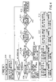
- FIG. 4 illustrating the main flowchart for processing carried out by the CPU 101.
- the CPU 101 When the power switch (not shown) of the image display device 10 is turned on, the CPU 101 first carries out initialization on each part of the display device (step S101). After that, the CPU causes the initial screen to appear on a screen area 115A of the monitor 115 of the second display unit 12 as shown in FIG. 5 (step S102) .
- the initial screen is one on which image select information, such as file icons and file names, is displayed so that the names and hierarchy of files and folders (directories) in the storage device 104 can be identified and specified.
- the first display unit 11 is placed in the non-display state.
- the CPU then enters the wait state until the touch panel 116 is operated (step S103).
- the CPU 101 When some operation is performed on the touch panel 116, the CPU 101 first makes a decision of whether or not that operation is to select a file of data to be visually displayed, or to be visually presented on the first display unit 11 (hereinafter referred to as presentation data) (step S104) . If the decision is that a presentation data file select operation has been performed, then the CPU 101 activates the selected presentation data file (in this example, presentation data 1) and application software, which is stored in the ROM 102 and is needed to process the presentation data 1, and allocates the data file and application software to a window A in small-screen display state (step S105). After that, the application 1 activation flag (not shown) provided in the RAM 103 is set to one (step S106) and then a display control routine is called (step S107).
- presentation data in this example, presentation data 1
- application software which is stored in the ROM 102 and is needed to process the presentation data 1
- step S105 the application 1 activation flag (not shown) provided in the RAM 103 is set to one (
- step S107A a decision is first made as to whether or not the application 1 activation flag in the RAM 103 is one. If the flag is one, then the allocated presentation data 1 is displayed in the specified window A of the first display unit 11 by the display control unit 108 (step S107B). After that, return is made to the main routine.
- the image 51 of the presentation data 1 is displayed in the window A 50 in the small-screen display state appearing in front of the background image on the screen area 115A of the monitor 115 of the second display unit 12.
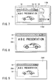
- the image 51 of the presentation data 1 which is to be displayed in the window A 50 is displayed on the entire projection screen area 20A of the screen 20 of the first display unit 11 as shown in FIG. 8.
- an image is displayed on the entire screen of the first display unit 11 on starting application software regardless of an entire-screen display button.
- step S104 a decision is made as to whether or not it is an operation of the button for deactivating the window A 50 (step S108). That is, the window A 50 contains a small-screen display button 52, an entire-screen display button 53, and a deactivation button 54 in addition to the screen 51 for the presentation data 1.
- step S108 a decision is made as to whether the deactivation button 54 has been operated with the pen 30. If the decision is that the deactivation button 54 of the window A 50 has been operated, then the CPU 101 deactivates the selected presentation data 1 and its associated application software (step S109). After that, the CPU resets the application 1 flag in the RAM 103 to zero (step S110) and then calls such a display control routine as described above (step S107).
- the application 1 activation flag is decided to be zero in step S107A and the display control unit 108 sets the first display unit 11 to the non-display state (step S107C).
- the main routine As a result, such an initial screen as shown in FIG. 5 will appear on the screen area 115A of the monitor 115 of the second display unit 12.
- the first display unit 11 is stopped from making projection display.
- step S108 If the decision in step S108 is that the operation of the touch panel 116 is not an operation of the deactivation button 54 of the window A 50, a decision is further made as to whether or not it is an operation of the entire-screen display button 53 (step S111). If the decision is that the entire-screen display button 53 of the window A 50 has been operated, then the CPU 101 sets the entire-screen flag (not shown) in the RAM 103 to one (step S112) and then calls such a display control routine as described above (step S107) . In this case, since the application 1 activation flag has not been rewritten, no change will occur in the display state even if the display control routine is executed.
- step S111 If the decision in step S111 is that the operation of the touch panel 116 is not an operation of the entire-screen display button 53, a decision is further made as to whether or not it is an operation of the small-screen display button 52 (step S113). If the decision is that the small-screen display button 52 of the window A 50 has been operated, then the CPU 101 resets the entire-screen flag (not shown) in the RAM 103 to zero (step S114) and then calls such a display control routine as described above (step S107). In this case as well, since the application 1 activation flag has not been rewritten, no change will occur in the display state even if the display control routine is executed.
- step S113 If the decision in step S113 is that the operation of the touch panel 116 is not even an operation of the small-screen display button 52, then processing corresponding to that operation is carried out (step S115). This processing is not directly related to the invention and the description thereof is therefore omitted. Return is then made to the wait state in step S103 for an operation of the touch panel 116.
- steps S111 through S114 may be omitted.
- the image display device 10 is configured such that the CPU 101 detects the operating state of given application software and, based on the detected operating state of the application software, the CPU 101 and the display control unit 108 switch the first display unit 11 between display and non-display states. Accordingly, it becomes possible to provide security for data which must not be openly displayed to viewers other than the operator.
- the first display unit 11 projection displays an image on the entire screen as shown in FIG. 8.
- the first display unit may projection-display an image on a small section of the screen as in the case of the second display unit 12 shown in FIG. 7.
- image select information such as file icons and file names, is not to be displayed on the background 20A1 of the window A 50 as shown in FIG. 9.
- the selected presentation data 1 is displayed on the window A 50 that is smaller than the screen of the second display unit 12 as shown in FIG. 7.
- the image 51 of the presentation data 1 is projection-displayed by the first display unit 11.
- the first embodiment may be modified in such a way as to display only the image select information, such as file icons and file names, on the second display unit 12 as shown in FIG. 10.
- a mark indicating being selected is displayed in a discernible manner.
- the selected icon is displayed in a specific color.
- the small-screen display button 52, the entire-screen display button 53 and the deactivation button 54 are floating displayed.
- the mark need not be limited to color.
- the shape may be changed or the arrangement on screen may be changed.
- a third modification of the first embodiment will be described.
- the display state may be changed according to an operation of either of these buttons by changing the display control routine in step S107 as shown in FIG. 11.
- step S107A a decision is made as to whether or not the application 1 activation flag in the RAM 103 is one. If the decision is one, a decision is further made as to whether or not the entire-screen display flag in the RAM 103 is one (step S197D). This entire-screen display flag has been initialized to zero in step S101. The flag is set to one in step S112 and resets to zero in step S114.
- step S104 When the display control routine is called after the decision that presentation data has been selected (step S104), the entire-screen display flag has been set to zero. In this case, therefore, the decision is NO in step S107D and the display control unit 108 then controls the first display unit 11 into the non-display state (step S107C). Return is then made to the main routine. Thereby, as shown in FIG. 7, with the initial screen containing the image select information, such as file icons and file names, as background image 115A1, the image 51 of the presentation data 1 is displayed in the small-screen display state window A 50 appearing in front of that background image on the screen area 115A of the monitor 115 of the second display unit 12. The fist display unit 11 is in the non-display state.
- the image select information such as file icons and file names
- step S111 When the display control routine is called after the decision that the entire-screen display button for the window A 50 has been operated (step S111), the entire-screen display flag has been set to one in step S112. In this case, therefore, the decision is YES in step S107D and the display control unit 108 displays the allocated presentation data 1 in the specified window A 50 of the first display unit 11 (step S107B). Return is then made to the main routine. Thereby, as shown in FIG. 12, only the image 51 of presentation data 1 within the window A 50 is displayed on the entire screen area 115A of the monitor 115 of the second display unit 12. At this point, as shown in FIG. 8, only the image 51 of presentation data 1 within the window A 50 is displayed on the entire screen area 20A of the screen 20 of the first display unit 11 as well.
- step S113 When the display control routine is called after the decision that the small-screen display button 52 has been operated (step S113), the entire-screen display flag has been set to zero in step S114. In this case, therefore, the decision is NO in step S107D and the display control unit 108 then controls the first display unit 11 into the non-display state (step S107C). Return is then made to the main routine.
- the image select information such as file icons and file names
- background image 115A1 As background image 115A1
- the image 51 of the presentation data 1 is displayed in the small-sized window A 50 appearing in front of that background image on the screen area 115A of the monitor 115 of the second display unit 12.
- the first display unit 11 does not make a small-screen display but is set to the non-display state.
- the third modification is configured such that, only when two conditions of the activation of application software and the operation of the entire-screen display button 53 are met, a screenful of image is displayed on the first display unit 11 (and the second display unit 12).
- the first and second display units 11 and 12 may display an image in different manners, for example, in different resolutions. That is, the second display unit 12 is allowed to display the image on a small screen area.
- the image display device may be provided with an operating switch as indicated at 119 in FIG. 1 in order to allow the first display unit 11 to provide selectively switched display as described in the present embodiment or continuous (normal) display.
- the second embodiment is configured in such a way as to retain display unit setting table in the nonvolatile storage device 104 and control the display switching of the first display unit 11 (and the second display unit 12) in accordance with the table contents.
- the display unit setting table can be set up as display control tables for each user, for each application software, and for each file as shown in FIGS. 13, 14 and 15.
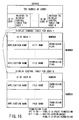
- the setting items in those tables may be integrated into a table for each user as shown in FIG. 16.
- the second embodiment is described hereinafter in terms of the integrated type display unit setting table shown in FIG. 16.
- the display control table for each user comprises the ID of the user having authority for operation, the number, the name of application software to be display controlled, the file name including the location of the file, and permission flag.
- the permission flag is composed of two bits; the bit 0, when on, indicates public display permission and the bit 1, when on, indicates entire-screen-based public display permission.
- the number indicates the number of sets each of application name, file name and permission flag.
- the location refers to the location where a corresponding file exists in a hierarchical directory; for example, "c: ⁇ usr ⁇ tato ⁇ data1.”
- the display unit setting table is updated automatically in the following manner.
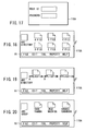
- the CPU 101 first makes such a display as shown in FIG. 17 on the monitor 115 of the second display unit 12. Only when the operator correctly enters the user ID and password through the touch panel 116 is the display device allowed to operate. In this case, a user ID in the display unit setting table is identified through the entered user ID.
- the CPU 101 when the correct password is entered, the CPU 101 causes an initialization screen to appear on the monitor 115 of the second display unit 12, thereby allowing the user to carry out initialization of contrast, brightness, etc. After that, the CPU causes such a file select screen as shown in FIG. 18 to appear on the monitor 115.
- the operator By displaying the file select information containing file icons and names on the monitor 115, the operator is prompted to select a file containing an image to be shown to a number of viewers. That is, the operator can move between directories or specify a specific file on the file select screen.
- application software which operates that file is identified.
- files have been read from the memory card 40 or downloaded from a server or personal computer over a network into the storage device 104. It is also possible to directly specify a file on the memory card 40 or network-connected server or personal computer.
- FIG. 19 shows a screen which appears on the monitor 115 of the second display unit 12 when "Application” is selected from the pop-up menu.
- FIG. 20 likewise shows a screen which appears on the monitor 115 of the second display unit 12 when "Operator" is selected. In each of these screens, selecting "Edit” allows another pop-up menu to be displayed and selecting each item in this menu allows another screen to appear.
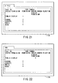
- FIG. 21 shows a setting screen which appears on the monitor 115 of the second display unit 12 when a file is specified on the select screen of FIG. 18.
- FIG. 22 shows a setting screen which appears on the monitor 115 of the second display unit 12 when a directory is specified.
- setting is applied to files contained in that directory.
- the user ID and the authority of the user (change, execution, write, read) are displayed.
- properties as to whether to permit public display and whether to permit entire-screen-based public display are displayed.
- the CPU 101 allows the first display unit 11 to operate when, in the case where public display is selected, corresponding application software is activated or when, in the case where entire-screen-based public display is selected, corresponding applications software is activated and its window is placed in the entire-screen display state. For example, to initialize brightness, contrast, and so on not through the second display unit 12 but through the first display unit 11, the user marks the public display permission column of an initialization file with X. When wanting to present a file to a number of viewers, the user marks its entire-screen-based display permission column.
- the CPU 101 performs display control on the basis of the display unit setting table, thereby allowing the first display unit 11 to provide public display only when the image display device is initialized and when the entire-screen-based presentation of a specified file is given.
- the monitor 115 of the second display unit 12 makes display for the operator alone. The user is relieved of troublesome operations by merely performing such straightforward settings. In addition, security is also ensured spontaneously.
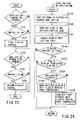
- FIG. 23 illustrates only the display switching of the first display unit 11 which is characteristic of the present embodiment.
- starting and stopping of actual application software and operations based on the application software are carried out by the CPU 101 and the display output switching processing is called when necessary.
- the second display unit 12 provides display all the time.
- step S151 a decision is made as to whether an operating state where application software is started or stopped has been reached. If the operating state has been reached, image display is considered as being permitted and the procedure goes to the following steps. That is, a decision is made as to whether or not the operating switch 119 is ON (step S152) . If it is OFF, no display output switching processing is carried out. If, on the other hand, it is ON, the procedure goes to a first display control routine in which, as will be described in detail later using FIG. 24, comparison with the display unit setting table is made and, if conditions are met, the display output switching is performed (step S153) .
- step S154 a decision is made as to whether the window has been changed to the entire screen display state.
- step S155 a decision is made as to whether the operating switching is ON or OFF. If it is OFF, no display output switching processing is carried out. If, on the other hand, it is ON, the procedure goes to a second display control routine in which, as will be described in detail later with reference to FIG. 25, comparison with the display unit setting table is made and, if conditions are met, the display output switching is performed (step S156) .
- FIG. 24 shows the first display control routine which is called in step S153.
- the name of an application which has its operating state changed is taken out of the RAM 103 managed by the OS (step S153A). Further, the user ID and the file name are taken out (step S153B).
- a search is then made for a table corresponding to such integrated type display unit setting table as shown in FIG. 16 (step S153C). This process is performed by finding the address of the display control table of a user whose ID matches that user ID in the display unit setting table header and then searching the display unit setting table for a match in application name and file name. If there is no match (step S153D), the processing comes to an end because the display output remains unchanged (not switched).
- step S153D If, on the other hand, there is a match (YES in step S153D), the corresponding public display permission flag is verified (step S153E). If the flag is ON, a decision is made as to whether the first display control routine has been called by starting or stopping application software (step S153F). If it has been called by starting application software (YES in step S153F), the display control unit 108 applies the output of the image processing unit 107 to the first display unit 11 (the liquid crystal panel control unit 109) (step S153G). Thereby, projection display is made by the first display unit 11.
- the display control unit 108 stops applying the output of the image processing unit 107 to the first display unit 11 (the liquid crystal panel control unit 109). Thereby, projection display by the first display unit 11 is stopped (step S153H) .
- step S153E If the public display permission flag is OFF in step S153E, nothing is performed. That is, the procedure comes to an end with the display output kept unchanged (not switched).
- FIG. 25 shows the second display control routine which is called in step S153E.
- the window size of applications software having its window size changed is taken out (step S156A). This window size value is stored in the RAM 103 managed by the OS.
- a decision is next made as to whether the second display control routine has been called due to change from non-entire-screen display state to entire-screen display state (step S156B). If the routine has been called due to change to entire-screen display state, a decision is made as to whether the corresponding user ID, application name and file name of the opened file exist in the display unit setting table (step S156C). If they exist (YES in step S156D), a decision is made as to whether the entire-screen-based public display flag is ON (step S156E). If it is ON, the display control unit 108 applies the output of the image processing unit 107 to the first display unit 11 (liquid crystal panel control unit 109) (step S156F). Thereby, the window is projected on the entire screen by the first display unit 11.
- step S156D If the decision in step S156D is that the corresponding user ID, application name and file name do not exist in the display unit setting table or the decision in step S156E is that the entire-screen-based public display flag is not ON, nothing is performed. That is, the procedure comes to an end with the display output kept unchanged (not switched).
- step S156B determines whether the second display control routine has not been called due to change from non-entire-screen display state to entire-screen display state.
- a decision is made as to whether it has been called due to change from entire-screen display state to non-entire-screen display state (step S156G). If the decision is NO, the procedure comes to an end as it is. If the routine has been called due to change from entire-screen display state to non-entire-screen display state, a decision is made as to whether the corresponding user ID, application name and file name of the opened file exist in the display unit setting table (step S156H).
- step S156I a decision is made as to whether the entire-screen-based public display flag is ON (step S156I). If it is ON, the display control unit 108 stops application of the output of the image processing unit 107 to the first display unit 11 (liquid crystal panel control unit 109), thereby stopping the projection display by the first display unit 11 (step S156K). In this case, it goes without saying that the window is displayed on a small-screen basis on the monitor 115 of the second display unit 12.
- step S156I If the decision in step S156I is that the corresponding user ID, application name and file name do not exist in the display unit setting table or the decision in step S156J is that the entire-screen-based public display flag is not ON, nothing is performed. That is, the procedure comes to an end with the display kept unchanged (not switched).
- the second embodiment is configured in such a way as to retain the display unit setting table in the nonvolatile storage device 104 and control the display switching of the first display unit 11 in accordance with the table contents. Accordingly, appropriately rewriting the contents of the display unit setting table allows display switching to be made as the operator desires.
- the display unit setting table have been described as being stored in the storage device 104, they may be stored in the memory card 40. In such a case, the memory card can be carried together with image files and loaded into another image display unit, allowing display switching using the display unit setting table to be made on that display device.
- the second display unit 12 is provided integrally with the image display device 10, it may be constructed as an external display device which is connected to the device 10 by a cable or radio link.
- the first display unit 11 may be kept ON to project a white image onto the entire screen 20.
- the computer refers to a device which is composed of an entry unit (a mouse, keyboard, touch panel, etc.), a control unit (CPU), a storage unit (a RAM, disk device, etc.), and an output unit (a display device, printer, etc.) and executes processing in accordance with the definitions of software.
Landscapes
- Engineering & Computer Science (AREA)
- Multimedia (AREA)
- Signal Processing (AREA)
- Theoretical Computer Science (AREA)
- Computer Security & Cryptography (AREA)
- Physics & Mathematics (AREA)
- Computer Hardware Design (AREA)
- Human Computer Interaction (AREA)
- General Engineering & Computer Science (AREA)
- General Physics & Mathematics (AREA)
- Databases & Information Systems (AREA)
- Software Systems (AREA)
- Computer Graphics (AREA)
- Controls And Circuits For Display Device (AREA)
- User Interface Of Digital Computer (AREA)
- Digital Computer Display Output (AREA)
Abstract
Description
Claims (17)
- An image display device for displaying an image to viewers, the image display device comprising first display means (11) for displaying the image, characterized by further comprising:application state detecting means (101) for detecting the operating state of predetermined application software; andcontrol means (191, 108) for controlling whether to operate the first display means or not in accordance with the operating state detected by the application state detecting means.
- The device according to claim 1, characterized in that
the operating state which the application state detecting means detects includes the starting state of the application software, and
when the start of the application software is detected by the application state detecting means, the control means sets the first display means to a state where it is permitted to display an image associated with the application software. - The device according to claim 1, characterized in that
the operating state which the application state detecting means detects includes the stopping operation state of the application software, and
when the stopping operation of the application software is detected by the application state detecting means, the control means sets the first display means to a state where it is not permitted to display an image associated with the application software. - The device according to claim 1, characterized in that
the operating state which the application state detecting means detects includes the entire-screen display state of a window associated with the application software, and
when the entire-screen display state of the window associated with the application software is detected by the application state detecting means, the control means sets the first display means to a state where it is permitted to display an image associated with the started application software on an entire-screen display basis. - The device according to claim 2 or 4, characterized in that the control means causes the first display means to display only the image associated with the application software set to the permitted state.
- The device according to claim 1, characterized by further comprising state setting means (101, 116, 30, 12) for setting an operating sate that the application state detecting means detects for each application software.
- The device according to claim 1, characterized by further comprising state setting means (101, 116, 30, 12) for setting an operating sate that the application state detecting means detects for each image data and/or for each directory storing the image data.
- The device according to claim 1, characterized by further comprising state setting means (101, 116, 30, 12) for setting an operating sate that the application state detecting means detects for each operator.
- The device according to one of claims 6 to 8, characterized by further comprising state storing means (104) for storing the operating state of each application software set by the state setting means.
- The device according to claim 9, characterized in that the state storing means includes a portable storage medium.
- The device according to claim 2 or 4, characterized by further comprising a switch (119) for turning ON/OFF the first display means, and that
when turned ON by the switch, the first display means displays only an image which has been set to the permitted state by the control means. - The device according to claim 3, characterized by further comprising second display means (12) for displaying an image to an operator of the image display device, and that
the control means caused at least the second display means to display an image associated with application software set to the non-permitted state. - A program which controls image data to be output to an external display device connected to a computer, characterized in that the program causes the computer to perform the following functions:an application state detecting function of detecting the operating state of application software running on the computer; anda display control function of controlling the image data to be output to the external display device according to the operating state detected by the application state detecting function.
- The program according to claim 13, characterized in that
the operating state which the application state detecting function detects includes the starting state of the application software, and
the display control function includes a function of output image data to the external display device when the start of the application software is detected by the application state detecting function. - The program according to claim 13, characterized in that
the operating state which the application state detecting function detects includes the stopping operation state of the application software, and
the display control function includes a function of stop the output of image data to the external display device when the stopping operation of the application software is detected by the application state detecting function. - The program according to claim 13, characterized in that
the operating state which the application state detecting function detects includes the entire-screen display state of a window associated with the application software, and
the display control function includes a function of output image data to the external display device when the entire-screen display state of the window associated with the application software is detected by the application state detecting function. - A method which controls image data to be output to an external display device connected to a computer, characterized by comprising the steps of:detecting the operating state of application software running on the computer; andcontrolling the image data to be output to the external display device according to the detected operating state.
Applications Claiming Priority (2)
| Application Number | Priority Date | Filing Date | Title |
|---|---|---|---|
| JP2003048052A JP2004258242A (en) | 2003-02-25 | 2003-02-25 | Image display device and program |
| JP2003048052 | 2003-02-25 |
Publications (2)
| Publication Number | Publication Date |
|---|---|
| EP1452943A2 true EP1452943A2 (en) | 2004-09-01 |
| EP1452943A3 EP1452943A3 (en) | 2008-05-07 |
Family
ID=32767740
Family Applications (1)
| Application Number | Title | Priority Date | Filing Date |
|---|---|---|---|
| EP04002909A Withdrawn EP1452943A3 (en) | 2003-02-25 | 2004-02-10 | Image display device, image data control program and image data control method |
Country Status (3)
| Country | Link |
|---|---|
| US (1) | US7321363B2 (en) |
| EP (1) | EP1452943A3 (en) |
| JP (1) | JP2004258242A (en) |
Cited By (2)
| Publication number | Priority date | Publication date | Assignee | Title |
|---|---|---|---|---|
| EP1909257A4 (en) * | 2005-07-12 | 2010-01-27 | Nikon Corp | PROJECTION DEVICE EQUIPPED WITH A DISPLAY MONITOR |
| EP3316172A1 (en) * | 2016-10-25 | 2018-05-02 | Ricoh Company Ltd. | Information processing apparatus, information processing method, and carrier means |
Families Citing this family (40)
| Publication number | Priority date | Publication date | Assignee | Title |
|---|---|---|---|---|
| CN1662946A (en) * | 2002-04-26 | 2005-08-31 | 东芝松下显示技术有限公司 | Driving method of EL display device |
| US7774606B2 (en) | 2005-01-20 | 2010-08-10 | The Invention Science Fund I, Inc | Write accessibility for electronic paper |
| US7865734B2 (en) * | 2005-05-12 | 2011-01-04 | The Invention Science Fund I, Llc | Write accessibility for electronic paper |
| US8281142B2 (en) * | 2005-01-20 | 2012-10-02 | The Invention Science Fund I, Llc | Notarizable electronic paper |
| US8063878B2 (en) | 2005-01-20 | 2011-11-22 | The Invention Science Fund I, Llc | Permanent electronic paper |
| US7643005B2 (en) * | 2005-01-20 | 2010-01-05 | Searete, Llc | Semi-permanent electronic paper |
| US7669245B2 (en) * | 2005-06-08 | 2010-02-23 | Searete, Llc | User accessibility to electronic paper |
| US7856555B2 (en) * | 2005-01-20 | 2010-12-21 | The Invention Science Fund I, Llc | Write accessibility for electronic paper |
| US8640259B2 (en) * | 2005-01-20 | 2014-01-28 | The Invention Science Fund I, Llc | Notarizable electronic paper |
| US7739510B2 (en) * | 2005-05-12 | 2010-06-15 | The Invention Science Fund I, Inc | Alert options for electronic-paper verification |
| US20070008338A1 (en) * | 2005-05-28 | 2007-01-11 | Young-Chan Kim | Display system, display apparatus, and method of controlling video source and display apparatus |
| JP2006350207A (en) * | 2005-06-20 | 2006-12-28 | Casio Comput Co Ltd | Projection system, data processing apparatus, projection method and program |
| JP5157092B2 (en) * | 2005-07-12 | 2013-03-06 | 株式会社ニコン | Projection device with display monitor |
| JP4646304B2 (en) * | 2005-08-09 | 2011-03-09 | 株式会社日立ソリューションズ | E-mail system for broadcast communication |
| WO2007043378A1 (en) * | 2005-10-07 | 2007-04-19 | Nikon Corporation | Electronic device |
| JP4876610B2 (en) * | 2006-02-14 | 2012-02-15 | セイコーエプソン株式会社 | Image display system, image display method, image display program, recording medium, data processing apparatus |
| JP4961791B2 (en) * | 2006-03-27 | 2012-06-27 | 株式会社湯山製作所 | Drug cart |
| JP2007310799A (en) * | 2006-05-22 | 2007-11-29 | Nippon Avionics Co Ltd | Image file selection method |
| US20080136973A1 (en) * | 2006-12-08 | 2008-06-12 | Ellis Park | Portable projector system |
| JP2008225819A (en) * | 2007-03-13 | 2008-09-25 | Nec Personal Products Co Ltd | Information processing system, terminal, and program |
| JP5074827B2 (en) * | 2007-06-01 | 2012-11-14 | キヤノン株式会社 | Image presentation apparatus and method |
| US8757812B2 (en) * | 2008-05-19 | 2014-06-24 | University of Washington UW TechTransfer—Invention Licensing | Scanning laser projection display devices and methods for projecting one or more images onto a surface with a light-scanning optical fiber |
| JP5309777B2 (en) * | 2008-08-08 | 2013-10-09 | 株式会社ニコン | projector |
| JP5369865B2 (en) * | 2009-04-24 | 2013-12-18 | コニカミノルタ株式会社 | Image providing apparatus, image providing method, and computer program |
| JP5306046B2 (en) * | 2009-05-01 | 2013-10-02 | キヤノン株式会社 | Image processing system, device operation screen generation method, program, and information processing apparatus |
| JP2011039500A (en) * | 2009-07-17 | 2011-02-24 | Nikon Corp | Electronic apparatus |
| JP2011186572A (en) * | 2010-03-05 | 2011-09-22 | Hitachi Consumer Electronics Co Ltd | Video display device system |
| JP5156820B2 (en) * | 2010-11-16 | 2013-03-06 | 株式会社 富士サポート | Image display control software |
| JP5682457B2 (en) * | 2011-06-03 | 2015-03-11 | カシオ計算機株式会社 | Data processing apparatus and program |
| CN102270095A (en) * | 2011-06-30 | 2011-12-07 | 威盛电子股份有限公司 | Multi-display control method and system thereof |
| JP2012014181A (en) * | 2011-08-11 | 2012-01-19 | Casio Comput Co Ltd | Image output device and program |
| JP5779085B2 (en) * | 2011-12-22 | 2015-09-16 | インターナショナル・ビジネス・マシーンズ・コーポレーションInternational Business Machines Corporation | Information processing apparatus, screen output system, screen output control method, and program |
| JP5816596B2 (en) * | 2012-06-13 | 2015-11-18 | 日立マクセル株式会社 | Display control apparatus and display control method thereof |
| JP2014182521A (en) * | 2013-03-18 | 2014-09-29 | Fujitsu Ltd | Display control program and information processing apparatus |
| JP6090233B2 (en) * | 2014-05-21 | 2017-03-08 | カシオ計算機株式会社 | Data processing apparatus and program |
| JP5835404B2 (en) * | 2014-05-26 | 2015-12-24 | セイコーエプソン株式会社 | Image display device and method for controlling image display device |
| CN104267915B (en) | 2014-09-09 | 2018-01-23 | 联想(北京)有限公司 | A kind of information processing method and electronic equipment |
| JP6361670B2 (en) * | 2016-02-22 | 2018-07-25 | カシオ計算機株式会社 | Image output apparatus, image processing method, and program |
| JP6365579B2 (en) * | 2016-04-01 | 2018-08-01 | カシオ計算機株式会社 | Data processing apparatus, data output method, and program |
| JP7119371B2 (en) * | 2017-12-27 | 2022-08-17 | コベルコ建機株式会社 | Crane and information display method |
Family Cites Families (10)
| Publication number | Priority date | Publication date | Assignee | Title |
|---|---|---|---|---|
| JP3223886B2 (en) | 1988-04-26 | 2001-10-29 | 富士ゼロックス株式会社 | Recording device |
| JP2995730B2 (en) | 1988-04-26 | 1999-12-27 | 富士ゼロックス株式会社 | Display device for user interface |
| US5757418A (en) * | 1992-07-31 | 1998-05-26 | Canon Kabushiki Kaisha | Television conference system and method therefor |
| WO2000079791A1 (en) * | 1999-06-17 | 2000-12-28 | 3M Innovative Properties Company | Freeze-frame function in an electronic projection system |
| KR20010087603A (en) * | 2000-03-08 | 2001-09-21 | 고대수 | internet advertisement picture display apparatus |
| AU2001271538A1 (en) * | 2000-06-26 | 2002-01-08 | Viomagic Corporation | Electronic presentation system using portable storage device in place of a personal computer |
| JP4291467B2 (en) * | 2001-03-01 | 2009-07-08 | 株式会社ソニー・コンピュータエンタテインメント | Entertainment device, menu display method, and information recording medium |
| WO2002075518A1 (en) * | 2001-03-15 | 2002-09-26 | Seiko Epson Corporation | Printing control and image processing control |
| JP2002189548A (en) | 2001-08-10 | 2002-07-05 | Fuji Xerox Co Ltd | Display device, recording device including the display device, and display method |
| TWM246701U (en) * | 2003-01-20 | 2004-10-11 | First Int Computer Inc | Status display device |
-
2003
- 2003-02-25 JP JP2003048052A patent/JP2004258242A/en active Pending
-
2004
- 2004-02-09 US US10/775,866 patent/US7321363B2/en not_active Expired - Fee Related
- 2004-02-10 EP EP04002909A patent/EP1452943A3/en not_active Withdrawn
Cited By (4)
| Publication number | Priority date | Publication date | Assignee | Title |
|---|---|---|---|---|
| EP1909257A4 (en) * | 2005-07-12 | 2010-01-27 | Nikon Corp | PROJECTION DEVICE EQUIPPED WITH A DISPLAY MONITOR |
| US8908077B2 (en) | 2005-07-12 | 2014-12-09 | Nikon Corporation | Projection device with display monitor |
| EP3316172A1 (en) * | 2016-10-25 | 2018-05-02 | Ricoh Company Ltd. | Information processing apparatus, information processing method, and carrier means |
| US10412236B2 (en) | 2016-10-25 | 2019-09-10 | Ricoh Company, Ltd. | Information processing apparatus, information processing method, and non-transitory computer-readable storage medium |
Also Published As
| Publication number | Publication date |
|---|---|
| EP1452943A3 (en) | 2008-05-07 |
| US20040164977A1 (en) | 2004-08-26 |
| JP2004258242A (en) | 2004-09-16 |
| US7321363B2 (en) | 2008-01-22 |
Similar Documents
| Publication | Publication Date | Title |
|---|---|---|
| US7321363B2 (en) | Image display device, image data control program and image data control method | |
| US7134078B2 (en) | Handheld portable user device and method for the presentation of images | |
| KR100952860B1 (en) | Network projector interface system | |
| CN1329798C (en) | System and method for managing software application programme in figure user interface | |
| US6970145B1 (en) | Method and apparatus for controlling image-display devices collectively | |
| US6380957B1 (en) | Method of controlling view of large expansion tree | |
| CN107111496B (en) | Customizable blade applications | |
| CN101669165B (en) | Apparatus, system and method for presenting images in a multi-display environment | |
| US8381136B2 (en) | Handheld electronic device supporting multiple display mechanisms | |
| EP3396510B1 (en) | Image processing device, image display method, and program | |
| US20070109580A1 (en) | Information processing device, information processing method, program, and storage medium | |
| US20060168531A1 (en) | Information processing apparatus and method for controlling the same | |
| KR20100108422A (en) | Method and apparatus for displaying video data from multiple source computers in a multi-monitor computer system | |
| JPH09146751A (en) | Window display method and window management device | |
| US10990344B2 (en) | Information processing apparatus, information processing system, and information processing method | |
| JP2001136504A (en) | Information input / output system and information input / output method | |
| US20060150108A1 (en) | Information processing device, information processing method, storage medium, and program | |
| US7921366B2 (en) | Information processing apparatus, assignment method and display method of information processing apparatus, and computer-readable program product | |
| JP2006215531A (en) | Information processing device, information processing method, storage medium and program | |
| CN101714077A (en) | Device and method for graphically managing computer desktop | |
| CN113687750A (en) | Screenshot processing method and device | |
| JP2002268868A (en) | Multi-monitor system | |
| JP4147802B2 (en) | Projector selection support server, projector selection support device, projector selection support method, projector selection support program, and storage medium | |
| JP2001312264A (en) | Image processing device and presentation support device | |
| US10713393B2 (en) | Information processing system, information processing apparatus, method of controlling the same, and storage medium |
Legal Events
| Date | Code | Title | Description |
|---|---|---|---|
| PUAI | Public reference made under article 153(3) epc to a published international application that has entered the european phase |
Free format text: ORIGINAL CODE: 0009012 |
|
| AK | Designated contracting states |
Kind code of ref document: A2 Designated state(s): AT BE BG CH CY CZ DE DK EE ES FI FR GB GR HU IE IT LI LU MC NL PT RO SE SI SK TR |
|
| AX | Request for extension of the european patent |
Extension state: AL LT LV MK |
|
| PUAL | Search report despatched |
Free format text: ORIGINAL CODE: 0009013 |
|
| AK | Designated contracting states |
Kind code of ref document: A3 Designated state(s): AT BE BG CH CY CZ DE DK EE ES FI FR GB GR HU IE IT LI LU MC NL PT RO SE SI SK TR |
|
| AX | Request for extension of the european patent |
Extension state: AL LT LV MK |
|
| AKX | Designation fees paid |
Designated state(s): DE FR GB |
|
| STAA | Information on the status of an ep patent application or granted ep patent |
Free format text: STATUS: THE APPLICATION IS DEEMED TO BE WITHDRAWN |
|
| 18D | Application deemed to be withdrawn |
Effective date: 20080830 |