-
A portion of the disclosure of this patent document contains material which is
subject to copyright protection. The copyright owner has no objection to the
facsimile reproduction by anyone of the patent disclosure, as it appears in the
Patent and Trademark Office patent files or records, but otherwise reserves all
copyright rights whatsoever.
-
The present invention relates to a method which utilizes at least two energy bands
of x-rays to inspect objects subject to x-ray inspection (e.g. baggage) for a specific
substance which can be characterised by a specific composite atomic number 'Z'.
-
It is known to inspect objects using single energy x-rays to present an image of the
objects with shading representing varying degrees of mass density (opaqueness to x-rays).
-
It is known to inspect objects using a dual-energy x-ray system and to present an
image with colour proportional to the ratio of one energy band to the other on a
pixel by pixel basis.
-
Such x-ray inspection systems incorporate an x-ray single or dual energy source, a
conveyor, slider, or scanning system to scan the object to be inspected with the x-ray
beam, a detector or array of detectors that convert the x-ray flux which
penetrates the object to be inspected into pixels of values which represent the x-ray
image(s) resulting from the scan, a computing element which may optionally filter,
average, enhance, contrast adjust, or otherwise process the image of values output
from the detector system, and a display system which presents a black and white or
colour display of the resulting image of pixel values.
-
It is known to employ a dual energy x-ray inspection system and to use the value of
the ratio of one energy band's attenuation values to the other to discriminate
between low-Z material (plastics) and high-Z materials (metals) and to display the
respective values as a colour difference in the displayed image. These systems
display the resulting high-Z to low-Z colour-encoded image based on the value of
the ratio of the attenuation values at the high and low bands of x-rays for each pixel
at a time repeated for every pixel in the image. This method is unable to distinguish
composite materials such as metal over plastic and in these cases, an intermediate
colour is displayed.
-
The discrimination ability of these systems is insufficient to discriminate adequately
between different types of plastics or plastic-like materials, and in the presence of
overlying materials, is unable to accurately indicate the presence of specific plastics
or metals.
-
The present invention features, in general, a device and method of operation for
detecting a specific material that may be present in an ensemble of objects. The
device includes means to expose an area of the ensemble to x-ray energies to
produce dual energy image information of the ensemble. The device further
includes means to computer-process such dual energy information to detect the
specific material on the basis of comparisons of selected subareas of the exposed
area to other subareas in the vicinity of the selected subareas.
-
The invention further features, in general, a device and method of operation for
detecting a bomb that may be present in a container of objects. The device includes
means to expose an area of the container to x-ray energies to produce dual energy
information of the container and its contents. The device further includes means to
computer-process such dual energy information to detect the bomb on the basis of
comparisons of selected subareas of the exposed area to other subareas in the
vicinity of the selected subareas.
-
According to one aspect of the invention, there is provided a device for detecting
plastic explosive objects in packages or luggage which contain non-explosive plastic,
or plastic-like objects in an initially unidentified ensemble of objects comprising a
conveyor for sequentially moving packages or luggage through an inspection region,
a stationary x-ray exposure system located at said inspection region and positioned
to expose sequentially said packages or luggage comprising an initially unidentified
ensemble of objects in said inspection region to x-ray radiation of at least two
substantially different energies, a stationary x-ray detection system positioned to
detect x-ray radiation transmitted through an item of luggage or package, said
detection system providing data corresponding to the intensity of transmitted
radiation of said two energies, a computer operatively connected to said detection
system to receive said data and programmed to calculate a value of a specific
property of a plastic explosive object in said item of luggage or package, and
automatically discriminate said plastic explosive object from non-explosive plastic,
or plastic-like objects that are present in said initially unidentified ensemble of
objects based on said calculated value of said specific property, said automatic
discrimination utilizing x-ray transmission data of rays passing through said item of
luggage or package, and near but not through said plastic explosive object to
remove by computer calculation the contribution of unwanted overlying and
underlying material of said ensemble of objects from the calculated value of said
specific property of said plastic explosive object and said computer programmed to
automatically indicate, based on said discrimination, presence of said plastic
explosive object while said item of package or luggage progresses on said conveyor.
-
According to another aspect of the invention, there is provided a method of
detecting specific material of interest in an initially unidentified ensemble of objects,
comprising providing a stationary x-ray exposure system, a stationary x-ray
detection system, and a computer operatively connected to said detection system,
moving sequentially on a conveyor an initially unidentified ensemble of objects
through an inspection region, exposing, at said inspection region, said ensemble of
objects to x-ray radiation of at least two substantially different energies, detecting x-ray
radiation transmitted through said ensemble of objects, and providing to said
computer x-ray data corresponding to the intensity of transmitted radiation of said
two energies, calculating a value of a specific property of a specific material of
interest in said ensemble of objects, and automatically discriminating said specific
material of Interest from other objects that are present based on the calculated value
of said specific property in said automatic discrimination utilizing x-ray transmission
data of rays passing through said initially unidentified ensemble of objects, and near
but not through said specific material of interest to remove by computer calculation
the contribution of unwanted overlying and underlying material of said ensemble of
objects from the calculated value of said specific property of said specific material
of interest, and automatically indicating, based on said discrimination, presence of
said specific material of interest while said ensemble of objects progresses on said
conveyor.
-
The preferred device and method of operation for detecting a specific material that
may be present in an ensemble of objects comprises means to expose an area of the
ensemble to x-rays of at least two substantially different energy bands to produce
dual energy image information of the ensemble. The device further includes means
to computer-process such dual energy information to detect the specific material on
the basis of comparisons between attenuation image information from at least one
of the energy bands and positionally corresponding image information of parameter
P values derived from correlations of the dual energy image information with values
in a predetermined lookup table reflecting attenuation at high and low energy bands
over a range of thicknesses of a selected specific material and a range of thicknesses
of a representative overlay material, with attenuation of a constant thickness of the
overlay material and varying thicknesses of the specific material represented by the
parameter P.
-
In preferred embodiments, the means to computer-process includes means for
evaluating gradients of values in at least one of the images and/or means for
evaluating gradients of values in both the attenuation image and the image of P
values. The device provides means for selecting the regions of the attenuation
image information for the comparisons on the basis of the steepness of gradients of
attenuation values in the attenuation image. The above devices further provide
means for selecting which employs an edge finding operator. The device also
includes means for generating gradient values HS for substantially all subareas and
means for pruning to remove subareas with HS values below a selected threshold,
and means for thereafter performing the comparisons using the remaining HS
values.
-
The invention preferably provides a device and method of operation for detecting
and indicating the probable presence of a specific material in an ensemble of
objects, comprising means for exposing the item to x-rays of at least two
substantially different energy levels, means for generating for each subarea over the
exposed area a set of data values representing logarithms of x-ray attenuation at the
subarea at each of the energy levels, means for processing the data for the subarea
to compute the values of (H,L) for the subarea, where in H is the logarithm of the
attenuation of the x-rays at the subarea at the higher energy level and L is the
logarithm of the attenuation of the x-rays at the subarea at the lower energy level,
and means for applying an edge finding or gradient evaluating operator such as a
sobel operator to image data of at least one energy level, means for generating
gradient values HS for substantially all subareas, means for pruning to remove
subareas with gradient values HS below a selected gradient threshold, means for
determining for remaining subareas with gradient values HS above the selected
gradient threshold parameter P values using a lookup table in computer storage
reflecting x-ray attenuation at high and low energy bands over a range of thicknesses
of the selected specific material and a range of thicknesses of a representative
overlay material, with attenuation of a constant thickness of the overlay material and
varying thicknesses of the specific material represented by the parameter P, means
for applying the gradient evaluating operator to P image data formed using the
parameter P values for the remaining subareas, means for generating gradient values
PS for the remaining subareas, means for calculating a ratio HS/PS for the remaining
subareas, means for raising the ratio to a power at least as large as unity to
emphasise large values of the ratio, and means for storing the ratio HS/PS raised to
the power for substantially all of the remaining subareas. The device further
comprises means for selecting an alarm threshold on the ratio HS/PS raised to the
power above the alarm threshold are strongly indicative of presence of the specific
material, means for applying a dilation algorithm using the H values and the L
values for the image data, means for sounding an alarm if a certain number of
subarea values are above the alarm threshold, means for applying an erosion
algorithm to eliminate spurious noise in the image data, and means for displaying
the image data with areas of particular interest highlighted.
-
The invention further preferably provides a device comprising means to expose an
area of the ensemble to x-rays of at least two substantially different energy bands
and detection means responsive to the x-rays passing through the ensemble to
generate for subareas over the exposed area respective sets of values representing
the attenuation of the x-rays at each of the energy bands. Comparison means are
employed, operative on differences in attenuation between subareas in a
neighbourhood to determine the presence of a specific material in the
neighbourhood, and indicating means are provided responsive to the comparisons,
for indicating the presence of the specific material in the ensemble.
-
Preferably the indicating means of the device is a visual display of an x-ray image
and the indication is of the form of distinguished subareas at which the specific
material is probably present.
-
Preferably the comparison means of the device includes a lookup table reflecting
attenuation at high and low energy bands over a range of thicknesses of a selected
specific material and a range of thicknesses of a representative overlay material.
Attenuation of a constant thickness of the overlay material and varying thicknesses
of the specific material is represented by a parameter P. The device includes means
to reference actual attenuation measurements of subareas at an energy band with
parameter P values for said subareas, and using the determination in determining
the presence of the specific material.
-
Various preferred embodiments have one or more of the following features. The
comparison means of the device include means to combine, according to a
predetermined formula, values representing the attenuation of the x-rays for
subareas in the neighbourhood to provide an attenuation measure that reflects the
difference in the attenuation qualities between the subareas and means to compare
the measure to a reference related to the specific material or materials for which the
inspection is conducted. Preferably, the values generated by the device representing
the attenuation of the x-rays at the energy bands are logarithms of x-ray attenuation
at each of the energy bands at each subarea.
-
In preferred embodiments, the comparison means of the device comprises means
for computing for a selected test subarea of the exposed area the values (HT,LT )
wherein HT is the logarithm of the attenuation of the x-rays at the higher energy
band at the test subarea and LT is the logarithm of the attenuation of the x-rays at
the lower energy band at the test subarea, and means for computing for a subarea
nearby the test subarea the values (HB,LB ) wherein HB is the logarithm of the
attenuation of the x-rays at the higher energy band at the nearby subarea and LB is
the logarithm of the attenuation of the x-rays at the lower energy band at the nearby
subarea. The comparison means are constructed to employ the values (HT,LT ) and
(HB,LB ) in determining the presence of the specific material or materials.
-
Preferably, the device further comprises means for providing p-values P
representing attenuation characteristics of various overlying materials, means for
associating a p-value PT with the values (HT,LT) with the p-value PT proportional to
the thickness of overlying materials at the test subarea, and means for associating a
p-value PB with the values (HB,LB) with the p-value PB proportional to the
thickness of overlying materials at the nearby subarea. The device further includes
means for computing the value of | (HT-HB)/(PT-PB) | = ΔH /ΔP and means for
associating ΔH/ΔP with a relative probability measure for the presence of the
specific material at respective subareas. In some embodiments, the relative
probability measure is proportional to (ΔH/ΔP)q, with q being a value chosen to
emphasise extrema of the value of ΔH /ΔP. In particular embodiments, q=2.
Preferably in these devices the means for associating a p-value P with the values
(H,L) involves identifying the values with respective points from a set of points
previously generated by numerically varying thicknesses of the specific material and
the overlying materials.
-
Furthermore, in various embodiments, the device features means for computing the
value of (HT-HB )/(LT-LB ) = KTB and means for comparing the value of KTB with
the value of KMAT wherein KMAT is an attenuation characteristic of a specific material
for which the inspection is being conducted. In one such embodiment KMAT is a
stored value developed by prior measurements and in another such embodiment
KMAT - µH/µL determined by calculations wherein µH is the attenuation coefficient of
the specific material exposed to the higher energy band x-rays and µL is the
attenuation coefficient of the specific material exposed to the lower energy band x-rays.
-
In preferred embodiments, the device further comprises means for exposing
selected numbers of samples of various known materials each of a range of different
thicknesses to the x-rays of the different energy bands to measure the attenuation
characteristic of the exposed samples to provide a reference for the comparison
means. Certain embodiments further feature calculation means for interpolating
between the measured values to estimate intermediate values for use in making the
comparison.
-
In preferred embodiments, the device further comprises means for assigning to
subareas, over the exposed area of the object, relative probabilities for the presence
of the specific material based upon the comparisons, the indicating means being
responsive to these relative probability assignments for indicating presence of the
specific material in the object.
-
The preferred device and method of the invention also feature a baggage inspection
device for detecting and indicating the probable presence of a specific material in an
item of baggage comprising means to expose an area of the item to x-rays of at least
two substantially different energy bands and detection means responsive to the x-rays
passing through the item to generate for subareas over the exposed area
respective sets of values representing the attenuation of the x-rays at each of the
energy bands. Comparison means are employed which are operative on differences
in attenuation between subareas in a neighbourhood to determine the presence of a
specific material in the neighbourhood of the subareas and indicating means
responsive to the comparisons for indicating presence of the specific material in the
article. The comparison means comprise means for computing for a selected test
subarea of the exposed area the values (HT,LT ) wherein HT is the logarithm of the
attenuation of the x-rays at the higher energy band at the test subarea and LT is the
logarithm of the attenuation of the x-rays at the lower energy band at the test
subarea, and means for computing for a subarea nearby the test subarea the values
(HB,LB) wherein HB is the logarithm of the attenuation of the x-rays at the higher
energy band at the nearby subarea and LB is the logarithm of the attenuation of the
x-rays at the lower energy band at the nearby subarea. The comparison means are
constructed to employ the values (HT,LT ) and (HB,LB ) in determining the presence
of the specific material.
-
Preferably such a baggage inspection device features comparison means further
comprising means for providing p-values P representing attenuation characteristics
of various overlying materials, and means for associating a p-value PT with the
values (HT,LT ) with the p-value PT proportional to the thickness of overlying
materials at the test subarea, and means for associating a p-value PB with the values
(HB,LB ) with the p-value PB proportional to the thickness of overlying materials at
the nearby subarea. Such a device includes means for computing the value of | (HT-HB )/(PT-PB )
| = ΔH/ΔP, and means for associating ΔH/ΔP with a relative
probability measure for the presence of the specific material at respective subareas.
-
In various preferred embodiments, the device includes means for examining the
subareas and means responsive thereto for producing values for each subarea
indicative of the relative probability of matching the specific material. The device
includes means for displaying subareas over the exposed area of the ensemble, and
means for highlighting those subareas having a probability greater than or equal to a
selected threshold value of matching the specific material.
-
In other embodiments means are provided for computing the value of (HT-HB)/(LT-LB)
= KTB and means are provided for comparing the value of KTB with
the value of KMAT wherein KMAT is an attenuation characteristic of the specific
material.
-
In preferred embodiments of the devices described so far where the x-ray source is
polychromatic, KMAT = µH(HT,HB,LT,LB)/µL(HT,HB,LT,LB,) wherein µH , an
attenuation coefficient of the specific material exposed to the higher energy x-rays,
is a function of the logarithms of the attenuation of x-rays at the test subarea and at
the nearby subarea, and wherein µL , an attenuation coefficient of the specific
material exposed to the lower energy x-rays, is a function of the logarithms of the
attenuation of the x-rays at the test subarea and at the nearby subarea. Preferably
there are mans for ascertaining whether the value of KTB is within a selected window
of values of KMAT , means for incrementing a respective counter if the value of KTB
is within the window, means for examining the subarea counters and producing
values for each subarea indicative of the relative probability of matching the specific
material, means for displaying subareas over the exposed area, and means for
highlighting those subareas having a probability greater than or equal to a selected
threshold value of matching the specific material.
-
In preferred embodiments, the device possesses means to expose the area of the
object further comprising an x-ray source, means for generating from the source x-rays
of at least two substantially differeny energy bands, means for collimating a fan
beam of the x-rays, and means for conveying the object to intercept the fan beam of
the x-rays.
-
In various embodiments, the device is constructed specifically to detect a threat
substance, an explosive, an illicit drug substance, a mineral of value, or a particular
plastic. In some embodiments, the device is constructed to examine a stream of
matter, which may for instance be comprised of rocks and the device is constructed
to detect a mineral of value, or the stream can be shredded plastic refuse, and the
specific material can be a particular form of plastic, such as halogenated
hydrocarbon plastic to be separated from other plastic refuse. In other instances,
the objects can be foodstuffs such as meat and the specific material can be bone or
an inorganic contaminant.
-
Preferred embodiments of the devices described so far include means for locating
edges in the exposed area where one material overlaps another, means for choosing
subareas in close proximity to the edges to be the selected subareas, and means for
assigning to the selected subareas a relative probability for the presence of the
specific materials at the subareas based upon the comparisons with other subareas
in the vicinity and/or neighbourhood, the indicating means being responsive to the
relative probability assignment.
-
Preferred embodiments of the invention so far described further include means for
dilating indications of subareas over regions whose edges have been determined to
indicate the presence of the specific material. Such dilation makes the suspicious
regions more prominently noticeable to an operator of the device, and the dilation
enhances indication of presence of the specific material.
-
The invention features, as well, a specific method of baggage inspection for
detecting and indicating the probable presence of a specific material in an item of
baggage and a device for implementing the method. The preferred method
comprises the steps of exposing the item to x-rays of at least two substantially
different energy levels, generating for each subarea over the exposed area a set of
data values representing logarithms of x-ray attenuation at the subarea at each of the
energy levels, choosing a test subarea, filtering the data for the test subarea,
averaging the data for the test subarea, processing the data for the test subarea to
compute the values of (HT,LT ) for the test subarea, wherein HT is the logarithm of
the attenuation of the x-rays at the test subarea at the higher energy level and LT is
the logarithm of the attenuation of the x-rays at the test subarea at the lower energy
level, and choosing a background subarea, filtering the data for the background
subarea, averaging the data for the background subarea, processing the data for the
background subarea to compute the values of (HB,LB) for the background subarea,
wherein HB is the logarithm of the attenuation of the x-rays at the background
subarea at the higher energy level and LB is the logarithm of the value representing
the attenuation of the x-rays at the background subarea at the lower energy level,
and computing the value of KTB = (HT-HB)/(LT-LB), and comparing the value of
KTB to the value of KMAT, wherein KMAT = µH(HT,HB,LT,LB)/µL(HT,HB,LT,LB)
wherein µH, an attenuation coefficient of a specific material exposed to the higher
energy x-rays, is a function of the logarithms of the attenuation of the x-rays at the
test subarea and at the background subarea, wherein µL , an attenuation coefficient
of the specific material exposed to the lower energy x-rays, is a function of the
logarithms of the attenuation of the x-rays at the test subarea and at the background
subarea, and ascertaining whether the value of KTB is within a selected window of
values of KMAT, incrementing a respective counter if the value of KTB is within the
window, choosing another background subarea, and iterating the steps from
filtering the data for the background subarea to choosing another background
subarea until a substantial number of background subareas have been so examined,
and choosing another test subarea, and iterating the steps from filtering the data for
the test subarea to choosing another test subarea until substantially all subareas have
been so tested, and examining the subarea counters, producing values for each
subarea indicative of the relative probability of matching the specific material, and
displaying subareas over the area, and highlighting those subareas having a
probability greater than or equal to a selected threshold value of matching the
specific material.
-
The invention also features a specific method of baggage inspection for detecting
and indicating the probable presence of a specific material in an item of baggage
and a device for implementing the method. The method preferably comprises the
steps of exposing the item to x-rays of at least two substantially different energy
levels, generating for each subarea over the exposed area a set of data values
representing logarithms of x-ray attenuation at the subarea at each of the energy
levels, choosing a test subarea, filtering the data for the test subarea, averaging the
data for the test subarea, processing the data for the test subarea to compute the
values of (HT,LT ) for the test subarea, wherein HT is the logarithm of the
attenuation of the x-rays at the test subarea at the higher energy level and LT is the
logarithm of the attenuation of the x-rays at the test subarea at the lower energy
level, and choosing a background subarea, filtering the data for the background
subarea, averaging the data for the background subarea, processing the data for the
background subarea to compute the values of (HB,LB) for the background subarea,
wherein HB is the logarithm of the attenuation of the x-rays at the background
subarea at the higher energy level and LB is the logarithm of the value representing
the attenuation of the x-rays at the background subarea at the lower energy level,
providing p-values P representing attenuation characteristics of various overlying
materials, associating a p-value PT with said values (HT,LT) wherein said p-value PT
is proportional to the thickness of overlying materials at said test subarea,
associating a p-value PB with said values (HB,LB) wherein said p-value PB is
proportional to the thickness of overlying materials at said nearby subarea,
computing the value of |(HT-HB )/(PT-PB )| = ΔH/ΔP, associating ΔH/ΔP with a
relative probability measure for the presence of said specific material at respective
subareas, storing said probability measure, choosing another background subarea,
and iterating the steps from filtering the data for the background subarea to
choosing another background subarea until a substantial number of background
subareas have been so examined, and choosing another test subarea, and iterating
the steps from filtering the data for the test subarea to choosing another test
subarea, and iterating the steps from filtering the data for the test subarea to
choosing another test subarea until substantially all subareas have been so tested,
and examining the subarea probability measure stores, producing values for each
subarea indicative of the relative probability of matching the specific material, and
displaying subareas over the area, and highlighting those subareas having a
probability greater than or equal to a selected threshold value of matching the
specific material.
-
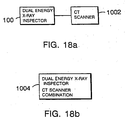
Preferably the methods described so far further include employing computed
tomographic information to detect the specific material that may be present in
subareas indicated by the computer-processed dual energy information as being
probable subareas for the presence of the specific materials.
-
The present invention provides a system for accurately discriminating specific
substances in an x-ray image of an object (such as an article of baggage), despite the
presence of overlying unknown background substances and features the
discrimination of arbitrary (which may be low-Z) materials in the presence of an
unknown background composed of a mix of overlying low-Z or high-Z materials.
-
Different types of plastics or plastic-like materials such as plastic explosives (C4,
RDX, etc.) and other kinds of explosives (TNT, DYNAMITE, etc.) can be
discriminated from innocuous materials in baggage, cargo, letters and small parcels,
or other objects to be inspected despite, and in the presence of, overlying objects
and materials.
-
Low-Z materials such as drugs (i.e. cocaine, heroin, marijuana, .....) can also be
discriminated.
-
Discrimination of specific plastic material from other plastic materials of different
composition can also be achieved as can the discrimination of foreign materials in
foods or foodstuffs or other manufactured items.
-
In preferred embodiments, the object to be examined is transported past the x-ray
beam on a conveyor or other slider mechanism as the x-ray beam at two energy
bands scans the object item and the attenuated x-rays are converted by a detector
array into a series of x-ray attenuation values which are then processed with a
computer system to discriminate one or more specific substances in the object. If a
sufficient amount of specific material is detected, an alarm is triggered and a visual
display device displays the pixels containing the suspect specific materials in a
colour (e.g., RED) over a normal black and white x-ray image. Additional image
enhancement algorithms can be applied to the displayed image under control of an
operator's console that can include zoom, contrast enhancement, colour processing
algorithms, such as the low-Z/high-Z ratio image, and other enhancements to
provide additional information to the operator to aid in threat discrimination where
threats may be defined as weapons as well as explosive substances and mechanisms.
-
In the following disclosure of preferred embodiments, the attenuation values of the
x-rays are described as being measured at 'pixels', but more generally, the
attenuation values can be measured at 'subareas' of the area exposed to x-rays, not
necessarily at given picture elements (pixels). Similarly, the specific material to be
detected is often a threat substance such as bomb material, but the present
invention is not limited to apply only to bombs.
-
Other advantages and features of the invention will become apparent from the
following description of preferred embodiments, by way of example only, with
reference to the accompanying drawings, in which:
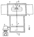
- Figure 1 is a schematic plan view of a device capable of baggage inspection;
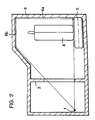
- Figure 2 is a side view cross section along line II....II in Figure 1;
- Fig. 3 shows a strip detector used in the device
of Fig. 1.
- Fig. 4 illustrates various areas and subareas in
the x-ray image of an exposed object.
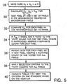
- Fig. 5 is a flow diagram for a monoenergetic
detection algorithm.
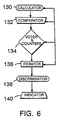
- Fig. 6 is a schematic diagram for a device that
can implement the monoenergetic and polychromatic
detection algorithms.
- Fig. 7 is a flow diagram for a polychromatic
detection algorithm.
- Fig. 8 is a more detailed flow diagram for
detection algorithms.
- Figs. 9(a)-(c) depict luminance dilation algorithm
effects.
- Fig. 10 is a flow diagram for generating a lookup
table.
- Fig. 11 illustrates diagrammatically a preferred
device in its entirety.
- Fig. 12 is a circuit diagram of the x-ray source
assembly of Fig. 11.
- Figs. 13a-13d illustrate the calibration shuttle
assemblies.
- Figs. 14a-14c illustrate the x-ray filter drum and
timing wheel details.
- Fig. 15 illustrates the conveyor, belt, and
baggage detection photocell assembly of Fig. 11.
- Figs. 16a and 16b illustrate the design and
construction of the x-ray detector array of Fig. 11.
- Fig. 17 details the major functional blocks
comprising the x-ray system of Fig. 11.
- Figs. 18a and 18b illustrate preferred embodiments
employing computed tomography with a dual energy x-ray
inspector.
- Fig. 19 is a flow diagram for a preferred
detection algorithm.
- Fig. 20 is a schematic diagram for a device that
can implement the preferred detection algorithm given in
Fig. 19.
-
Embodiment employing monoenergetic x-rays
-
As shown in Figs. 1 and 2, an x-ray source 1
produces a beam of x-rays at two substantially different
energies, two energy bands so narrow that each is
effectively monoenergetic. The source is spaced from the
front of a shielding tunnel 8 in position to expose
objects within the tunnel. The beam is collimated in the
fan beam collimator 3 made of lead or another material of
sufficient thickness to stop x-rays. The resulting fan
beam 2 encounters articles 4 such as pieces of luggage
and baggage moved through the beam path by a conveyor 5,
within shielding tunnel 8. The attenuated beam of x-rays
reaches a strip detector array 6, shown in more detail in
Fig. 3, made up of a series of individual x-ray detectors
7 of approximate dimensions 2mm x 3mm each made of a
scintillation crystal coupled to a photodiode. The
detector array 6 comprises two parts 6a and 6b (Fig. 2)
forming two sides of the tunnel 8, in the embodiment
shown, at the back and top of the tunnel.
-
The x-ray source 1 alternates between high energy
and low energy in order to obtain, for each pixel,
measurements of x-ray attenuation at both energies.
Because of continuing movement of the conveyor, the
precise points of exposure of the object for a given ray
at the alternate high and low energy will be slightly
offset, but the points can be treated as being the same
pixel because of their proximity. (In another
embodiment, as where reduced accruacy can be tolerated,
the x-ray source may simultaneously produce x-rays of
both the high and low energy and two sets of superposed
detectors can be used, one set sensitive to high energy
x-rays, the other set sensitive to low energy x-rays,
giving simultaneous detection of x-ray attenuation at
both energies at the same point.)
-
An attenuation measurement is taken for each pixel
simply as the ratio I/I o of detected x-ray intensity I at
the detector 6 (attenuated by the object) to the
unattenuated x-ray intensity I o measured at detector 6 in
the absence of the object, e.g. between articles on the
conveyor 5. A convenient quantity characterizing the
attenuation is the negative natural logarithm of the
ratio I/Io. Consequently, we define:
H = -ln(IH/Ih o) - ln(IH o/IH) - ln(IH o)-ln(IH),
where I H and I H o are, respectively, the high energy x-ray
intensity at the detector 6 and the high energy incident
x-ray intensity. Similarly, we define:
L = -ln(IL/IL o) = ln(IL o/IL) = ln(IL o)-ln(IL),
where I L and I L o are, respectively, the low energy x-ray
intensity at the detector 6 and the low energy incident
x-ray intensity.
-
The present embodiment acquires such attenuation
data over the region exposed to the fan beam and
processes it by a comparison technique to find whether or
not a specific material (an explosive, e.g.) is present
in the article 4 of baggage without knowing beforehand
whether the specific material is present or where the
material is located, and without knowing the composition
of the other materials in the article 4.
-
To do this, the embodiment is constructed to
acquire, for substantially all pixels over the exposed
region of the article 4, pairs of attenuation valves
(H,L) and compare the values between pairs of nearby
pixels to test whether differences in attenuation at the
different pixels can be attributed to the presence of a
specific material.
-
The algorithmic efficiency is substantially
enhanced by applying an edge finding algorithm, such as
the sobel edge finding algorithm that can be found in
standard image processing references, to the pixel data.
The binary pixel comparisons are then performed primarily
on the set of pixels within a given distance of an edge
found in the image data. Subjecting the detected x-ray
data to an edge finding or gradient evaluating algorithm
is generally useful in substantially all embodiments
described herein.
-
Consider, as in Fig. 4, a typical pixel 19,
assumed to be a background pixel. Identify with pixel 19
the attenuation values (H B ,L B ). Consider a nearby pixel
21 as a test pixel and identify with pixel 21 the
attenuation values (H T ,L T ). Calculate the quantity
(HT-HB)/(LT-LB) = KTB.
Let µ H be the attenuation coefficient of high energy
x-rays for the specific material of interest and let µ L
be the attenuation coefficient of low energy x-rays for
the specific material of interest. Compare the value of
K TB calculated for pixels 19 and 21 to the value of µ H /µ L .
If K TB equals µ H /µ L , then the difference in attenuation
between pixels 19 and 21 can be attributed to the
presence of the specific material of interest at pixel 21
and a record of the successful match is made for pixel
21. If K TB is not equal to µ H /µ L , then no attribution is
made. The inter-pixel spacing is generally small enough
(resolution high enough) that there is a likelihood that
the only substantial difference between the materials
encountered by the x-rays passing through pixels 19 and
21 is a certain thickness of the specific material of
interest present at pixel 21 and absent at pixel 19, the
other background materials being essentially the same for
both pixels. In Fig. 4, a layer of explosive material 23
is shown to overlie pixel 21 and K TB = µH/µL.
-
This comparison process is repeated for all other
background pixels in the neighborhood of test pixel 21
and then a different test pixel is substituted for test
pixel 21, and compared with another set of background
pixels in its neighborhood, until substantially all
pixels in the exposed region of the article 4 have been
treated as test pixels. The pixel records of successful
matches with the specific material of interest are
reviewed, over the area examined, by an automatic system
that applies statistical criteria to judge whether the
specific material of interest is likely to be present and
if so, the relevant pixels in the image, displayed on a
monitor 9 as shown in Fig. 1, are highlighted or
indicated in red or a bright, distinguishing color.
Comparisons for a number of specific materials and their
presence can be highlighted or indicated in the same or a
distinctive manner.
-
The detection algorithm for the present
monoenergetic embodiment is given schematically in Fig.
5. The first step (30) is to calculate K TB =
(H T -H B )/(L T -L B ) for test pixel #1 and a set of nearby
pixels in the neighborhood of test pixel #1 treated as
background pixels. Then (32), the value K TB when testing
the test pixel #1 against each background pixel in the
set is compared to µ H /µ L for the specific material(s) of
interest. If K TB = µ H/µ L , a "vote" is added (34) to the
"vote" count associated with the test pixel, keeping a
separate count for each pixel. This whole procedure
(30)-(34) is to be repeated (36) for each pixel as a test
pixel, keeping a running count of "votes" for all test
pixels. Then, selection criteria, such as whether or not
the number of "votes" for a pixel exceed a threshold
value, are applied (38) to the "vote" counts for all
pixels. Finally (40), pixels that meet the selection
criteria are indicated and distinguished in the standard
image on the monitor.
-
In conducting the above algorithm, for
computational efficiency, for any comparison in which the
value H T is less than H B (or not greater than H B by an
amount related to the accuracy of the system and the
nature of the material being detected), the computation
is not performed, and no vote is assigned (28).
-
A detector device embodying the detection
algorithm of Fig. 5 is shown in Fig. 6. A calculator 130
calculates K TB = (H T -H B ) / (L T -L B ) for test pixel #1 and a
set of nearby pixels in the neighborhood of test pixel #1
treated as background pixels. A comparator 132 takes the
output of calculator 130 and compares the value K TB for
each background pixel in the set nearby test pixel #1 to
µ H /µ L for the specific material(s) of interest. If K TB =
µ H /µ L , the comparator 132 alerts a voter 134 which then
adds a "vote" to the "vote" count associated with the
nearby pixel, keeping a separate count for each pixel.
An iterator 136 activates the calculator 130, comparator
132, and voter 134 so that the detector device operates
on each pixel as a test pixel, keeping a running count of
"votes" for all pixels. The output of the iterator 136
is input to a discriminator 138 which applies selection
criteria to the "vote" counts for all pixels. Pixels
that meet the selection criteria are passed on to an
indicator 140 where they are distinguished in the
standard image on the monitor.
Polychromatic x-ray embodiment
-
The polychromatic x-ray case must be considered
when the x-ray source delivers x-rays in energy bands
that are too broad to be considered monoenergetic. Then
the attenuation coefficients µ H and µ L are no longer
approximately constant characteristics of specific
materials, but generally become functions of the x-ray
attenuation values measured at high and low energies.
For example,
µH = µH(HT,LT,HB,LB),
and
µL = µL(HT,LT,HB,LB)
where all attenuation values (H T ,L T ,H B ,L B ) have been
compensated for the intervening air when the article of
baggage is absent. (Such air corrected attenuation
values are zero when nothing is in the beam.) The ratio
K MAT = µ H (H T ,LT,H B ,L B )/µ L (H T ,L T ,H B ,L B ) is then generally
also a function of the attenuation values,
K MAT = K MAT (H T ,L T ,H B ,L B ). In the preferred embodiment, a
lookup table for the function K MAT is generated
empirically and an interpolation formula is used to
furnish values for K MAT at any values of its arguments.
-
As in the embodiment employing monoenergetic
x-rays, embodiments employing polychromatic x-rays are
constructed to acquire, for substantially all pixels over
the exposed region of the article 4 (Figs. 1 and 2),
pairs of attenuation values (H,L) and compare the values
between pairs of nearby pixels to test whether
differences in attenuation at the different pixels can be
attributed to the presence of a specific material.
Consider again, as in Fig. 4, a typical pixel 19, assumed
to be a background pixel. Identify with pixel 19 the
attenuation values (H B ,L B ). Consider again a nearby pixel
21 as a test pixel and identify with pixel 21 the
attenuation values (H T ,L T ). Once more, calculate the
quantity
(HT-HB) / (LT-LB) = KTB.
-
Now, however, the value of K TB calculated for
pixels 19 and 21 is to be compared to the value of
K MAT (H T ,L T ,H B ,L B ) = µ H (H T ,L T ,H B ,L B )/µL(H T ,L T ,H B ,L B ) which is
found by consulting the lookup table and applying the
interpolation formula. Again, if K TB = K MAT (H T ,L T ,H B ,L B ),
then the difference in attenuation between pixels 19 and
21 can be attributed to the presence of the specific
material of interest at pixel 21 and a record of the
successful match is made for pixel 21, whereas if K TB is
not equal to K MAT, then no attribution is made. In Fig.
4, a layer of explosive material 23 still overlies pixel
21 and
K TB = K MAT (H T ,L T ,H B ,L B ) for polychromatic embodiments.
-
In both the embodiment employing monoenergetic
x-rays and in embodiments employing polychromatic x-rays,
"equality" between two values is taken to mean that both
values lie within a certain window of values. Two values
that do not lie within a certain window of values of each
other are "unequal". For example, if a specific bomb
material of interest is the high explosive C4,
manufactured to military specifications and hence fairly
uniform, K MAT is about 0.6 and the window of values is
narrow, plus or minus 0.01 from the central K MAT value
0.6. Narrower windows, such as plus or minus 0.001 from
the central K MAT value 0.6 are possible, but the smaller
the window, the fewer the "votes" and the ability to
discriminate between real bomb material and innocuous
material lessens which is not desirable. On the other
extreme, if the specific material of interest is a water
gel explosive , K MAT is again about 0.6 but the window of
values is wider, plus or minus 0.03 from the central K MAT
value 0.6. Similarly, Semtex is very C4-like but varies
widely in its manufacture because of many different
manufacturers using different kinds of oil, for example,
and so Semtex like water gels, requires a wider window
than C4. The appropriate size of window is determined on
a per substance basis.
-
The process of comparison of K TB to
K MAT (H T ,L T ,H B ,L B ) is repeated for all other background
pixels in the neighborhood of test pixel 21. The
neighborhood can be a square region 1.5 inches to a side
optimized to allow for spatial variations in the contents
of the piece of luggage being inspected. Then, a
different test pixel is substituted for pixel 21, and
compared with another set of background pixels in its
neighborhood, until substantially all pixels in the
exposed region of the article 4 have been treated as test
pixels. As in the embodiment employing monoenergetic
x-rays, the pixel records of successful matches with the
specific material of interest are reviewed, over the area
examined, by an automatic system that applies statistical
criteria to judge whether the specific material of
interest is likely to be present and if so, the relevant
pixels in the image are highlighted or indicated in red
or a bright, distinguishing color. Comparisons for a
number of specific materials and their presence can be
highlighted or indicated in the same or a distinctive
manner.
-
The detection algorithm for a polychromatic
embodiment is given schematically in Fig. 7. The first
step (228) is to make sure that the computation is to be
performed. The next step (230) is to calculate K TB =
(H T -H B )/(L T -L B ) for test pixel #1 and a set of nearby
pixels in the neighborhood of test pixel #1 treated as
background pixels. Then (232), the value K TB for each
background pixel in the set nearby test pixel #1 is
compared to a specific number found in the lookup table
which depends on µ H (H T , L T , H B , L B ) / µ L (H T , L T , H B , L B ) for the
specific material(s) of interest, and also on the
attenuation values (H,L) for test pixel #1 and nearby
background pixels in the neighborhood of test pixel #1.
If K TB equals this specific number, a "vote" is added
(234) to the "vote" count associated with the nearby
pixel, keeping a separate count for each pixel. This
whole procedure (230)-(234) is to be repeated (236) for
each pixel as a test pixel, keeping a running count of
"votes" for all pixels. Then, selection criteria, such
as whether or not the number of "votes" for a pixel
exceed a threshold value, are applied (238) to the "vote"
counts for all pixels. Finally (240), pixels that meet
the selection criteria are indicated and distinguished in
the standard image on the monitor.
-
The detector device shown in Fig. 6 is also used
for polychromatic embodiments by modifying the comparator
132. In the polychromatic case, the comparator 132 takes
the output of calculator 130 and compares the value of K TB
for each background pixel in the set nearby test pixel #1
to a specific number found in the lookup table which
depends on
µ H (H T ,L T ,H B ,L B )/µ L (H T ,L T ,H B ,L B ) for the specific
material(s) of interest, and also on the attenuation
values (H,L) for test pixel #1 and nearby background
pixels in the neighborhood of test pixel #1. If K TB
equals the specific number, the comparator 132 alerts the
voter 134 which then adds a "vote" to the "vote" count
associated with the nearby pixel, keeping a separate
running "vote" count for each pixel. Otherwise, the
detector device for the embodiments employing
polychromatic x-rays is the same as previously described
for the embodiment employing monoenergetic x-rays.
Structure and operation of a Particular embodiment
-
The inspection system is an x-ray instrumentation
system designed to inspect baggage for the presence of
threatening substances and materials.
-
The system in Fig. 11 consists of a pulsed
dual-energy x-ray source 91 emitting a fan beam 91a of
x-rays which penetrates the item to be inspected 91b; a
rotating filter drum and timing wheel 92 to filter the
fan-shaped beam of x-rays at two energy bands of x-rays
synchronized to the x-ray source 91; 2 calibration
shuttles 93, 94 which contain materials used to calibrate
and check the operation of the machine; a conveyor belt
95 or other means to scan the baggage past the x-ray
beam; an array of x-ray detectors 96 which provide
calibrated values of x-ray attenuations at all points of
the scanned item to a signal and image processing
computer 97 which processes the detector data to compute
the probability and location of threat substances to be
detected in the image, an alarm 98 which is triggered if
the processed image yields a value which exceeds a
certain threat threshold, and a display 99 which displays
the x-ray attenuation image with superimposed color
indication threat substance is present.
-
The system also includes a means of control
constituted by an operator's control console 100, which
provides control of the inspection system and its
operation, a footpad switch 110 to sense the operator's
presence, and various other features provided to
facilitate the system's operation in an industrial or
security environment.
X-ray source
-
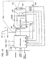
Referring to Fig. 12, the inspection system
consists of an x-ray source 120, capable of producing
pulsed beams of x-rays 121, which alternate between high
energy bands and low energy bands of x-rays. This x-ray
source consists of a high voltage transformer 122 with a
nominal primary voltage of 100 volts and having two
secondaries of 70 kV each, connected to an arrangement of
high voltage diodes 123. These diodes are connected to
an x-ray generating tube 124 such that on one set of
alternate half cycles, both transformer secondaries (140
kV) are connected across the x-ray tube, and on the other
set, only one of the secondaries (70 kV) is placed across
the x-ray generating tube. The voltage developed across
the x-ray generating tube is monitored by a resistive
voltage divider circuit 127 by the x-ray source
controller circuit 126 and the primary voltage is
adjusted accordingly.
-
All the above components, i.e., the x-ray
generating tube 124, the transformer 122, the diodes 123,
and monitoring cirucits 125, 126, 127 are mounted within
tank 336 and immersed in insulating oil. The tube
current during the low energy pulse of x-rays is also
monitored by means of resistive shunt 125 and the value
used by x-ray controller circuit 126 to adjust the tube
filament voltage via filament transformer 128 to maintain
the x-ray tube current at a constant value.
X-ray controller board
-
The x-ray controller board 126 receives 117 VAC
nominal at 50 or 60 Hz, timing, control, and interlock
signals from the System Interface Board (Fig. 17, 160),
tube voltage and current feedback from monitoring
circuits connected to the x-ray tube source, and supplies
energizing voltages to the HV transformer 122 and to the
tube filament transformer 128 to effect an accurate
series of 70 kVP and 140 kVP x-ray pulses at a uniform
dose, timing, and energy. In addition, the x-ray
controller provides status and readback signals to the
system host computer (Fig. 17, 164).
Calibration shuttles
-
The calibration shuttles (Figs. 13, 93, 94) are 2
assemblies placed next to the x-ray source tank 336 in
the x-ray beam 91a to allow the programmable insertion of
background and detected materials or foreground simulants
into the beam. The purpose of the calibration shuttles
is two-fold, to check the operation of the machine as
each sample of known materials should measure within
certain specified limits, and to monitor the long term
drifts of the instrument and to provide data used to
generate the K MAT lookup table used in the detection
algorithm.
-
One shuttle (Fig. 13b), the background material
shuttle 93, contains an assortment of background
materials 330-333, with several different thicknesses of
each, ranging from low-Z materials (plastics) to high-Z
materials (metals). The other shuttle (Fig. 13c), the
detected material shuttle 94, contains materials 341-344
which are accurate simulants of the desired substances to
be detected.
-
Each shuttle consists of strips 330-333 and 341-344
with several thicknesses of specific materials (Fig.
13d showing an endwise view of a strip) mounted on a
frame interleaved with empty areas 335 which are the
normal position, connected mechanically via a belt 345,
or as presently preferred, a lead screw, to a stepper
motor 334 which allows the shuttle position to be changed
by the controlling computer. An idler wheel 340 provides
mechanical stability.
-
During a calibration cycle, a procedure performed
when there is nothing in the beam (e.g., between bags), a
certain thickness of specific threat material is inserted
into the beam along with a certain thickness of a
specific background material, and the value stored, until
all combinations of background and threat materials have
been so measured with enough samples to be statistically
significant.
Filter drum and timing wheel
-
A motor driven spinning drum of plexiglas (Fig.
14a, 92) or other plastic is lined with strips of lead
151 and brass 152 aligned along the long axis (cross-section
view given in Fig. 14b) and inserted into the
x-ray beam to effect a filter for the high x-ray pulse
(140 kVP) and to effect a shutter with lead strips for
the transition area between high and low energy pulses to
effectively stop the beam for dark current compensation
during beam transitions.
-
A timing wheel 153 in Figs. 14a and 14b,
consisting of a disk with holes arrayed around the
perimeter and mechanically coupled to the filter drum,
acts in conjunction with 2 optical interrupter circuits
154 to issue low beam and high beam timing pulses to the
system interface board (Fig 17., 160), and ultimately to
the x-ray source and to the detector array electronics.
-
One of the timing wheel holes 155 is a double hole
providing a double pulse to the system interface board
thus providing the system with a reference to a specific
set of filter drum strips for possible calibration of
system timing to individual filter strips.
-
This assembly is driven from a line-synchronous
motor 156 and thus all timing pulses and x-ray pulses are
synchronized to line frequency providing a measure of
line-frequency rejection of system errors.
Conveyor
-
A motorized conveyor (Fig 15, 95) is provided
which moves the baggage (Fig. 11, 91b) or items to be
inspected at a constant rate past the x-ray beam (Fig.
11, 91a) and detector array 96 and delivers the inspected
baggage to a pickup area on the outlet side of the
machine.
-
This conveyor consists of a powered roller 180
mounted on the outlet side of the machine, an idle roller
181 at the inlet side, and a belt 182, mounted as a
continuous loop between the two rollers.
-
Control is provided at the operator console to
start and stop the conveyor as well as set its direction
(forward and reverse).
Baggage detection photocells
-
Two sets of light source- photocell combinations
183, 184 are provided to sense the position of the
baggage at two places along the belt, the first position
encountered as the baggage enters the x-ray tunnel (about
15" from the beam) and the other set an equal distance on
the other side of the beam 185.
-
The 2 levels of photocell item detectors allow
internal sequencing of the operation of the machine for
air point calibration and calibration shuttle sequencing
as well as times required for beam turn-on.
Detector
-
Referring to Fig. 16a, the detector array 170 is
an L-shaped arrangement of 960 detector elements and is
designed to detect a fan beam of x-rays (Fig. 11, 91a) at
high and low energy bands efficiently and rapidly with as
few errors, as little noise, as possible. Dynamic and
static calibration is done to provide the optimum level
of accuracy.
-
The detector array provides a digitized stream of
values representing the high and low x-ray band detection
values as well as dark current values for each detector
at a rate consistent with 240 x-ray flux values and 240
dark current values for each detector every second, at 60
Hz. (The system runs correspondingly slower at 50 Hz
delivering 200 samples per second and 200 dark current
values per second.) The detector provides these values
over a cable to the Detector Interface Board (Fig. 17,
161).
-
The Detector Interface Board computes dark current
compensation and air point subtraction algorithms and
provides a stream of equalized logarithmic values to the
transputer array (Fig. 17, 162).
-
The algorithm involved in transforming the
detector array output values into values sent to the
transputer array is detailed in Dark current and Air
point compensation, below.
Photodiodes and scintillators
-
Each detector consists of a large area photodiode
(Fig. 16a, 172), with a scintillating material 173 glued
over its active area with an optically transparent epoxy.
When exposed to incident x-ray radiation 174, the
scintillating material converts some of the x-rays to
visible photons, which are then converted to small
electric currents by the photodiodes.
-
It is important that the scintillating material
exhibit good efficiencies at both energy bands with
especially high efficiency at the low energy band of
x-rays. It must also exhibit very little 'afterglow'
which must decay very rapidly after the removal of the
x-ray flux.
-
The photodiodes are custom-made arrays, 32 per
array, optimized for active area and low noise
characteristics.
Electronics
-
The detector electronics (Fig. 16b, 178, 179) are
designed to amplify the nano-ampere signal currents from
the photodiodes, provide a small reverse bias to each
diode in the array, and integrate and amplify the
resulting currents to provide a voltage to be digitized
by the converter board. It is necessary that the
electronics contribute as little noise as possible to the
resulting signal.
Preamp/Mux board
-
The Preamp/Mux board assembly 178 consists of 2
printed circuit boards mounted together with an
intervening shield board to provide signal isolation and
x-ray shielding. Each board assembly contains 64
channels of a dual integrating functional block, one half
of the integrators being for high energy beams and one
half of the integrators being for low energy beams. This
block also provides a small reverse bias to each
photodiode in the array.
-
The signal output from the Preamp board 175 is
sent to the Multiplexor board 177 and distributed, 8
signals at a time via 8 analog busses, to the Analog-to-digital
(A/D) conversion board 179. The timing control
for the Mux board is received from the A/D board.
A/D board
-
The A/D board 179 receives timing information from
the detector interface board (Fig. 17, 161), mounted in a
VME card cage and backplane, and distributes timing
information to the array of detector Preamp/Mux boards
178. It then receives analog voltage information from
these modules, 8 lines at a time, and converts these
values to ranged 12 bit digital numbers. These values
are then output to the detector interface board 161 for
dark current and air point compensation.
-
The A/D board 179 also returns voltage status
information to the environmental monitoring board in the
VME card cage.
System Interface Electronics
-
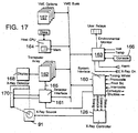
The System interface electronics (Fig. 17, 160,
161, 163) consists of 3 VME standard size cards mounted
in the VME card cage along with the host computer 164 and
its options, and the transputer array 162. These boards
perform the majority of the inspection system hardware
interface.
Detector Interface
-
The Detector Interface board 161 receives a stream
of digital values from the detector in response to timing
and control information provided to the detector by this
board.
-
This board also performs dynamic, value by value,
dark current correction and air point compensation, and
optionally dynamic filter drum calibration, (see Dark
current and Air point compensation, below).
-
The detector interface board also does logarithmic
conversion of the data and finally sends the data to the
transputer array via a transputer link 165.
System Interface
-
The system interface board 160 receives timing
information for the filter drum timing wheel and issues
customized timing pulses based on a synchronized crystal
controlled clock signal and various state-machine based
circuits. These pulses are then sent to the x-ray
controller board and to the detector interface board.
-
This board also receives interlock signals, from
both mechanical and electrical interlocks in the system,
and distributes interlock and control information to the
x-ray controller.
-
The system interface board controls the operation
of the stepper motor controlled calibration shuttles.
Environmental Interface
-
The Environmental Interface board 163 monitors all
DC and AC voltages as well as certain temperatures at
various places throughout the machine. If the monitored
parameters exceed certain programmable limits, warnings
are issued to the operator and the operation of the
machine can be inhibited.
-
This board also provides operator console
interface and supplies power and output signals to the
console to light switches or sound alarms, receives
information concerning switch closures, and data from the
console mounted touch panel area.
Operator Console
-
The operator console 166 is the primary means of
system control for the operator. It contains switches
that enable power and x-rays for the machine, switches
that control the action of the conveyor (stop, start,
direction), switches that control the operation of the
display to modify system display modes and contrast
adjustment, and a touch panel which provides a method of
moving a cursor or 'zoom window' around a display screen.
It also holds an alarm annunciator to provide audible
feedback signals to the operator.
-
The switch array includes switches that are
'deadfront' when inactive or unavailable to simplify the
operation and appearance to an unskilled operator. These
switches may provide a variable backlit intensity to
signal available options versus options currently in
effect.
Computer System
-
The computer system (Fig. 17) is structured as a
VME backplane containing a Host computer 164, which has
full access to all other cards mounted in the VME
backplane, various peripheral cards 167 which provide
disk storage, computer network communications, etc., and
an array of VME cards 162 which contain an independent
computer subsystem consisting of numerous computers,
known as Transputers manufactured by Inmos/Thomson,
interconnected so as to form a large network of 10 or
more transputers depending upon the application. This
transputer array is dedicated to processing the detector
array data received from the detector interface card to
primarily detect specific substances (threat materials)
in random baggage of unknown composition, and to produce
an image on a high quality color computer monitor screen
168.
Host and Peripherals
-
The host computer system 164 consists of a
commercially available processor board based on the Intel
80386 CPU and may optionally include peripheral circuitry
such as 4 MBytes of RAM, math co-processor, and a full
array of communication ports.
-
One of the peripheral boards in this group is the
mass storage peripheral card which provides a ruggedized
40 Mbyte hard disk, a 3 1/2 inch microfloppy disk, and
SCSI interface for future disk expansion.
-
All program code used by the host computer group
as well as the code used on the transputer array is
stored on the 40 Mbyte hard disk and downloaded into
operating RAM at system turn-on.
-
The Host has the responsibility for bootstrapping
all relevant code to the respective computing elements,
causing the system to respond to commands from the
operator via the operator console, continuously checking
all system voltages and temperatures by reading the
environmental monitor board, and providing operator
warning messages via the system annunciators or the
operators display screen.
Transputers
-
The Transputer array 162 is a series of
interconnected VME cards which provide the ability to
contain an arbitrary array of transputer modules, with
differing combinations of transputer types (16, 32 bit,
floating point) and external memory capacity. This array
of transputers can be programmably interconnected to form
networks of transputers with an aggregate computing
capacity of over 300 Mips (Million Instructions Per
Second). The algorithm employed to detect specific
threat materials in baggage is computationally intensive
and requires a computing element of this performance or
better to be able to image the data in near real time.
-
Each Transputer communicates with its neighbors in
the network via 4 built-in communication links with
direct memory access capability. The electrical and bit
protocol of these links is standardized among all
transputer types, and allows easy, transparent
communication from one transputer to another, one sender
and one receiver per link (communication is
bidirectional). The first transputer in the transputer
array receives data via a transputer link from the
detector interface card. The link interface is provided
on an integrated circuit, Inmos/Thomson C012, for
interconnection with non-transputer circuitry.
-
The final transputer in the network shares memory
with a high performance graphics adapter circuit, G300
from Inmos/Thomson. This circuit provides an image on
the monitor from data stored in memory providing up to
256 colors on a 1024 by 1280 computer monitor. This
circuit also provides up to 64 shades of grey for high
quality x-ray attenuation images.
-
The intervening network of transputers implement
all processing required to implement the image detection
algorithm detailed below in near real time. Certain
combinations of image data may involve an extraordinary
or unusual amount of processing. A memory buffer is
provided at the input side of the transputer array to
accommodate differing detector and image processing data
rates.
Display System
-
The display subsystem 168 incorporates a high
quality computer display monitor which can provide a
normal grey-scale x-ray image with color overlays to
highlight differing kind of threats and to provide color
and enhanced black and white images. Current resolutions
contemplated would be 960 by 1280 pixels.
-
An optional composite video converter can be
included which converts the RGB color monitor signals to
composite video for recording images on video tape.
-
A color graphics printer may be included to allow
for paper copies of on-screen images.
Processing and Mode Algorithms
-
The following algorithms are suitable for
detection of specific items in baggage. Extensive
non-linear averaging of pixel data in the image is
performed to increase accuracy of the detection
algorithm. Refer to Fig. 8.
Detection Algorithm
-
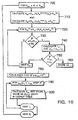
- 1. Take (H,L) data (400,410) for substantially
all pixels in the image or object to be
examined where H and L refer to the logarithm
of the x-ray attenuation at the high and low
energy x-ray bands, respectively.
- 2. Choose a pixel to be tested taken to be a
test pixel (420).
- 3. Compute the value (430) of (H T , L T ) for this
test pixel which may involve 1 or 2
dimensional filtering, averaging, or other
processing of pixel data.
- 4. Choose a nearby pixel to be a candidate
background pixel taken to be a background
pixel (440).
- 5. Compute the value (450) of (H B , L B ) for this
background pixel which may involve 1 or 2
dimensional filtering, averaging, or other
processing of pixel data, and determine (455)
that H T is greater than or equal to H B by an
amount ΔH related to the accuracy of the
system and the nature of the material to be
detected.
- 6. Compute the value (460):
KTB = (HT-HB)/(LT-LB)
- 7. In the case of mono-energetic x-ray band
spectra, compare this value of K TB to the
value of K MAT (470), where this value is
equal to
KMAT = µH/µL
where µ H and µ L are the attenuation
coefficients of a specific material in the
high and low bands of x-rays respectively,
or,
- 8. In the case of non-monoenergetic or
polychromatic x-ray band spectra, this value
is equal to
KMAT = µH(HT,HB,LT,LB)µL(HT,HB,LT,LB)
where µ H , µ L are functions of the specific
material to be detected as well as the
attenuation values of both the test pixel and
the background pixel.
- 9. If this value, K TB , is within a selected
window of values of K MAT , then increment a
counter (480) corresponding to the most
attenuated pixel of the pair, test and
background pixels, where each pixel in the
image has a corresponding counter stored in
memory.
- 10. Choose another background pixel (490), which
may be the next pixel in a square
neighborhood of pixels surrounding the test
pixel, or by use of a different algorithm
and,
- 11. Repeat steps 5 through 10 until a substantial
number of background pixels have been
examined (500).
- 12. Choose another test pixel (510), which may be
the next pixel in a line of pixels in the
image, or by use of a different algorithm
and,
- 13. Repeat steps 3 through 12 until substantially
all chosen pixels have been tested in the
image (520).
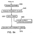
- 14. Examine the pixel counter data (530), and,
for all pixels with counts greater than or
equal to a selected threshold value, process
the counter data and the pixel data in the
image to produce values for each pixel that
indicate the relative probability that the
pixel under test is a match to a specific
material (540).
- 15. Display all pixels comprising a standard
x-ray attenuation intensity image (550) which
may use both H and L data to produce the
image on the display screen.
- 16. Process all pixels that have a probability
greater than a selected threshold of a match
to the specific material in a way that
produces a single value for the image, called
threat presence value. If this value exceeds
the threshold then an alarm, the threat
present alarm is triggered (560), and,
- 17. Display all pixels that have a probability
greater than or equal to a selected threshold
of a match to the specific material in a way
that highlights (570) these specific pixels
in the x-ray image (e.g., color).
-
Dark Current and Air Point Compensation
-
Periodically (once per item to be inspected) take
a sample of the x-ray detector output which is
proportional to incident x-ray flux, at both high and low
energy bands, with nothing in the beam (except the
intervening air) and store these values (X AirH ,X AirL ).
-
Periodically (once per x-ray pulse) take a sample
of the detector output with no x-ray flux (lead in the
beam) and store this value (χ Dark ).
-
Use these values, χAirH, χAirL, χDark, and the
output value of the detector with an item of interest in
the beam, χSampleH, χSampleL at high and low energy bands,
and calculate the value of the log attenuation of that
sample relative to air and dark current corrected as:
H = k Log10([χAirH-χDark]/[χSampleH-χDark])
L = k Log10([χAirL-χDark/[χSampleL-χDark])
where k = counts/decade.
Special Calibration and Procedures
Threat material calibration
-
Periodically, e.g. by use of the shuttle shown in
Fig. 13, insert a calibration material into the beam
which may consist of a number of specific foreground
materials or simulants as well as a number of background
materials, chosen such that the effective atomic number
'Z' of the background materials span a range of low-Z
(plastics) to high-Z (metals) in such a way that each
specific material is sampled over all the background
materials as well as air.
-
Store the measured value and accumulate (average)
the data until enough samples have been accumulated of
each combination of specific (threat) and background
materials to be statistically significant.
-
When enough samples have been accumulated, use
these values to determine K MAT for the specific material
(monoenergetic beams), or to regenerate the K MAT lookup
table (non-monoenergetic or polychromatic case).
-
There are two shuttles in the machine that can
insert various calibration materials into the fan beam of
x-rays. One of these shuttles is called the background
materials shuttle, the other is the threat substances
shuttle.
-
The operation of these shuttles is controlled by
the operation of 2 stepper motors which, in turn, are
driven via the system interface board by the host
software.
-
These shuttles contain strips of materials
interspersed with air gaps. Each material is represented
by 3 thicknesses of said material, to allow measurement
of several thicknesses of each material. The air gap is
positioned in the beam during normal baggage inspection.
-
These materials are of various types. The
background materials shuttle contains strips of 5
background materials, currently planned is iron (~1
mm/step), aluminum (~4 mm/step), lexan or lucite (~10
mm/step), melamine resin (~10 mm/step), and noryl (~10
mm/step).
-
The threat substance materials will be fabricated
from a combination of epoxy plastic and aluminum powder,
in a proportion that simulates various threat materials
in x-ray attenuation. These proportions will be
determined experimentally. The result is a hard
plastic-like material which can be machined into a series
of stepped wedges, see Fig. 13(d).
-
This arrangement allows the system to insert a
choice of background material of a particular thickness
and a choice of threat substance of a particular
thickness in the x-ray beam enabling measurements of
these materials during a calibration cycle (no baggage in
beam) or between successive bags on the conveyor.
-
This allows the system to take a series of
measurements that describe a matrix of background and
substance materials of various thickness. For example if
the background shuttle contains 5 substances of 3
thicknesses each (plus air) and the threat substance
shuttle contains 5 substances of 3 thicknesses each, then
a total of ((3*5)+1)*(15) or a total of 240 separate
combinations of background and threat substance materials
can be measured.
-
The high and low energy beam attenuations are
known for these 240 combinations, either due to the
mechanical thicknesses and tolerances of these known
materials or due to factory calibration values stored for
each of these combinations in the machine.
-
These values can therefore be used to verify
calibrated operation of the machine by checking the
values stored or calculated against the values measured
during a verification cycle.
-
The measurements of the shuttle materials may be
averaged in order to increase the accuracy of the data.
A likely number of samples averaged together may range
from as few as 10 to as many as 1000 samples per
measurement per detector element.
-
These measurements can be used to calibrate the
system by generating correction constants, that, when
applied to the data from the detector array, serve to
correct the data to compensate for long-term drift of the
system due to aging or other unknown phenomena.
Experimental Demonstration
-
A series of measurements of various objects were
made using the Hologic QDR 1000 dual energy x-ray bone
densitometer adapted with custom software. These objects
consisted of stepped wedges of various materials that
approximate the attenuation characteristics of materials
of interest, as well as sheets of these and other
materials.
-
The data taken consisted of a series of high and
low energy x-ray attenuation values (H,L), one set per
step in the wedges. Many samples of each step were taken
and averaged in order to lower the noise in each
measurement which is due to x-ray quantum noise as well
as electronic noise. The value of the x-ray flux in air
(no object in the beam) was taken at each step in the
wedge in order to accurately characterize the attenuation
of the incident x-ray flux by the measured object despite
time-related drifts of the x-ray data caused by
inaccuracies in the Hologic densitometer.
-
Two types of equations were derived from these
measurements. One set of equations was developed that
described the path in a mathematical space whose axes are
the high energy beam attenuation and the low energy beam
attenuation, hereafter referred to as HL space, of
multiple thicknesses of the same material, where the type
of material is characterized by a number called K m . K m is
the ratio of high energy beam attenuation H to low energy
beam attenuation L with a thin piece of a material
inserted into the x-ray beam and nothing else (i.e. the
beam is unfiltered by overlying substances). With
monochromatic x-ray beams this path would be a straight
line, but in the polychromatic case, this line is a curve
because of the beam 'hardening' effects. This path is
characterized by computing the expected low energy beam
attenuation L, given the high energy beam attenuation H
and K m of the material of interest. The value of the
high energy beam H is used as an independent variable
here and elsewhere because its value is primarily due to
Compton effect interactions and has very little energy
dependence and is basically proportional to mass. The
low energy beam interacts primarily due to the
photoelectric effect and as such is proportional to
energy and mass.
-
Another set of equations were developed that
described the "K ref " , or the ratio H/L of high energy to
low energy attenuation due to the insertion of a
particular substance over various types of other
materials. Here, the particular substance was
characterized by two numbers, K o , which represents the
ratio of high energy beam attenuation to low energy beam
attenuation with nothing else in the path (unfiltered
beam) and K L , which is the ratio of high energy beam
attenuation to low energy beam attenuation over heavily
filtering backgrounds. Note that K o and K m are identical
for a given substance. Here, K m refers specifically to
background materials, and K o refers to a substance of
interest (bomb substance).
-
K L cannot be directly measured, however, being the
value of K after essentially infinite filtering. Instead
a series of measurements are made of the high and low
beam attenuation of a substance over background
materials, which are then fit to a function of K o
(measured) and K L , resulting in a number for K L . The K ref
for any particular substance varies depending on what,
and how much, 'background' material is also in the beam,
i.e., it depends on the level of the incident x-ray beam
filtering. K ref for any substance can thus be described
as a function of the high energy beam attenuation (of the
background material), the K m of the background material,
and K o and K L for the substance of interest.
-
This set of equations and the values of the per
substance constants were all derived empirically from
measurements on the Hologic densitometer. The form of
the equations was experimentally determined by observing
the data and using a commercial statistics package to do
the non-linear regressions. In some cases data was taken
from actual x-ray images of baggage with bomb materials
inserted (also taken on the Hologic machine) and used to
determine some parameters of the fitted equations.
-
To convert these equations to a K ref lookup table
as a function of measured high energy and low energy beam
attenuations, a two pass process was used given
schematically in Fig. 10. In the first pass, a value of
high beam attenuation H is chosen (700). Then K ref for
these values of H, K o for the substance of interest, and
K m for aluminum (.26) was calculated (710). This will be
the highest K ref for the substance of interest (most
heavily filtered). Then K ref for the same values of H,
K o , and K m for plastic (.8) was calculated (710). This
will be the lowest K ref for the substance of interest (at
these values of high energy beam attenuation). Then 1%
changes (4% if high energy beam attenuation is greater
than 800) in K ref are incremented between these two values
of K ref (720, 730). At each iteration, the corresponding
value of the low beam energy attenuation L is calculated,
and the difference from the last value of low beam
attenuation is noted (740). If this difference value is
less than the last difference value (750), then it is
stored (760). After all values of K ref between the low
and high values of K ref have been calculated, the smallest
resulting increment of low beam attenuation is available.
-
This value of low beam attenuation difference is
rounded down to the nearest number that is a power of 2
(785), and this value used to generate the second pass
and the actual lookup table. The second pass iterates on
low beam attenuation (790), from the lowest value (over
the highest K m ) to the highest value (lowest K m ) resulting
in a series of equally-spaced (in low beam attenuation
value) entries in a table for a particular value of high
beam attenuation H, each entry containing the calculated
K ref for a particular substance (800). The spacing
between entries is a power of 2 to improve computational
efficiency, and the value of K ref from entry to entry is
guaranteed to be less than 1%. When the table is
finished it will have been iterated for all desired
values of high energy beam attenuation, currently 1 to
2000, which, at 819 values per decade of attenuation,
spans approximately 2 1/2 decades of attenuation. Beyond
this value of attenuation, no detection is performed in
the image because noise degrades the signals too much for
accurate detection.
-
This table can be used therefore, to detect bomb
substances by comparing the K ref of an object in an image
(i.e. its incremental k, determined by the equation
k=(H bmb -H bg )/(L bmb -L bg )) to the value in the lookup table
at the (H,L) coordinates of the background pixel.
-
The method so far described can be improved
somewhat. The equations developed so far to describe K ref
in HL space are modeled on thin pieces of the specific
substance to be detected, i.e. filtering due to a thick
piece of the detected substance causes the K ref
approximation to be less accurate. Essentially this
comes from treating the path that the specific substance
describes in the HL space, when placed over a background
substance, as a straight line. We know from the data
that this path is really a curved line, with the most
rapidly changing part of the curve nearest to air, i.e.
in lightly filtered beams. This means that the detection
algorithm stated above can be improved, especially when
inspecting thick bomb materials, and thin bags rather
than thick bags.
-
In order to improve the detection algorithm in
these situations, the K ref value in the lookup table at
the bomb (H,L) coordinates is also read, not just the
value at the background (H,L) coordinates. The value of
k (defined above) is then compared to
.8 (K ref background from table)+.2(K ref bomb+background from
table).
In order to improve the detection, curve fits were done
using data from images and this equation and were used to
generate new tables of K ref values. The values (.8,.2)
were arrived at with experimentation and were designed to
improve the detection in several images with little or no
background materials near the bomb material.
-
This method is valid for background materials with
Z's between plastic and aluminum. With higher Z
materials (lower K m ) such as iron, the set of equations
produce less valid values for the paths and the K ref s.
-
The equation that predicts paths of varying
thicknesses of substances in the HL space has known
inadequacies in predicting the paths of actual substances
with errors sometimes as great as 40 or 50 in low energy
beam attenuation values at 819 values per decade of
attenuation.
Detailed explanation of appendix ALGO.DOC (lookup table
generation and detection)
-
The appendix, ALGO.DOC, hereby incorporated by
reference, contains excerpts from the actual 'C' code
used to generate the lookup tables and do the detection
in the image. These are code fragments but should
describe all relevant algorithms.
-
Three constants are defined, MIN_HI, MAX__HI and
HI_INDEX, which define the valid range of the generated
table and lookup table granularity.
-
A specific flag is set (i.e. 'C4') to direct
generation for a specific bomb material.
-
Following this are defined the derived parameter
values for each type of material. Six 'z' parameters are
defined to be used for all materials, followed by five
material-specific parameters, c1, c2, c5, K0, and KL.
-
Five functions are then defined, bh(km),
alpha(km), beta(km), newlow(h,km), and K ref (Hi,km, kO).
The function K ref (which uses bh) calculates the value of
kref for a particular substance over a particular
background of a given attenuation. The function newlow
(which uses alpha and beta) calculates the corresponding
low energy beam attenuation value over a particular type
of background material with a particular value of high
energy beam attenuation (thus describing a 'path' in HL
space for various thickness of a given substance).
-
Two functions are then defined that iterate on the
above functions to find the value for parameters when no
specific equation for that relationship exists.
-
For example, no explicit function has been
described to provide a value for km given high beam
attenuation, K0 of a specific material and a particular
kref for that substance (over a background of the unknown
km). The function find_Km iterates on the function K ref
to approximate a value for km that satisfies the above
parameters.
-
Similarly the function find Km__low approximates
the desired value of km given a value of high and low
energy beam attenuations, i.e. the km for a background
material whose 'path' or locus of points in HL space
intersects the given value of hi and low attenuations.
-
Next is the fragment that describes the main
algorithm which generates the substance kref lookup
table. ('create the histogram')
-
A set of table entries for each value of high
energy beam attenuation are generated each time through
the main loop which increments the variable 'hint'. The
loop body is executed for each value of high beam
attenuation, and for a particular set of c1, c2, c5, K0,
and KL.
-
These parameters are used to generate the values
for hi_kref and lo_kref which are the kref values for a
particular substance with a specific K0 (and KL), over
aluminum (km=0.29) and plastic (km=0.8) respectively.
These end values of kref (at this value of high beam
attenuation) are used to define a loop which calculates
the value of the low beam attenuations at successive 1%
increments of kref. 4% increments are used if the value
of high beam attenuation exceeds a value of 800. Inside
this loop the smallest increment of low beam attenuation
resulting from these increments is stored. This value
for the smallest increment of low beam attenuation
required to insure 1% or less steps in kref, is rounded
down to a power of 2 ('tdiffl') and is used as the
increment in a second loop.
-
This second loop uses the current value of high
beam attenuation and generates a series of values of low
beam attenuations. These values of low beam attenuations
range between the kref endpoints with an increment of
'tdiffl' low beam attenuation values to generate the kref
lookup table. This table thus contains entries spaced at
periodic gridpoints in HL space (i.e. at specific values
of High and Low beam attenuations).
-
For each value of high beam attenuation, a header
containing the data specific to this set of entries is
stored. This header contains the first low value for
which data is stored ('MIN_LO'), the scale factor
('LO_SCALE' = tdiffl), and the largest value of low for
which data is stored ('MAX_LO'). This header data is
followed by the actual values for K ref for this set of
entries (corresponding to a particular high energy beam
attenuation value).
-
Finally, the number of kref 'bins' is output to
the console to provide a measure of storage required to
store the lookup table.
-
The detection algorithm is then documented in the
procedure DoBox.
Detection algorithm using the generated lookup table
-
The procedure DoBox, examines the high and low
beam attenuation data and produces a value for each pixel
at the center of a square neighborhood of pixels ('box')
which is a measure of the 'hit' or 'vote' count of this
center pixel measured against all pixels in this
neighorhood. This 'hit' or 'vote' count is a measure of
the probability that this pixel represents an unknown
amount of a particular substance over a 'background'
material represented by a nearby pixel.
-
Each invocation of DoBox represents the
calculations required for a single center pixel.
-
The function, AveragePixel, is called to perform a
2-d averaging for all like pixels in a neighborhood of
pixels to reduce noise.
-
If the averaged value of this pixel exceeds 2000
then it is deemed too opaque to examine.
-
A threshold is calculated that sets the minimum
difference in high beam attenuations between pixels that
enables the detection algorithm ('mindiff').
-
The main loop of the detection algorithm is
entered. If any pixel is on an edge ('px1->sobel') it is
not examined.
-
Each pixel to be compared to the center pixel is
then averaged (with like pixels in the neighborhood) and
thresholded in high and low beam values. If the
threshold is exceeded, kref at both the center and the
test pixels are retreived from the lookup table and are
tested in the equation 'krefavg=(kreflo*.8)+(.2*krefhi)'
where kreflo is the least attenuated of the test and
center pixels and krefhi the most attenuated of the two
pixels.
-
If the resulting value of krefavg is within a
window of values of "Diffk' then a count for the center
pixel is incremented ('midpxl->histval++'). This value
is then stored and is a measure of the probability that
the center pixel represents a specific substance over a
nearby background pixel. These threshold values,
MinThreshold and MaxThreshold, can be set in the command
line when the detection algorithm is invoked or else
defaults to -0.01, 0.01 if not otherwise specified.
Detection algorithm using 'p-value' lookup table
-
An alternative algorithmic embodiment involves a
'p-value' lookup table. This method creates a series of
'paths' or trajectories that describe various thicknesses
of bomb material over various thicknesses of 'basis'
materials. This is potentially much more accurate since
various thicknesses of bomb materials are correctly
modeled and the values produced are valid over the entire
basis set, i.e. boron to iron.
-
The detection algorithm detailed above and in the
appendix is modified to use the p-value lookup table by
replacing the kref lookup with a p-value lookup for both
the test pixel and the center pixel. These p-values are
compared, and if they are within a window of values of
each other, i.e. the difference between the two p-values
is 0 or a small number, such as 5, then the two pixels
are related by an overlying bomb substance.
-
In preferred embodiments, an edge finding or
gradient evaluating algorithm is applied to the data for
the H image (or, alternatively, the L image) and a P
image formed from the p-value data. An edge that showed
up in the H image data but not in the P image data would
be indicative of the presence of the specific substance
of interest. A convenient measure characterizing the
presence of an edge of the specific substance of interest
in the H image and its absence in the P image is given by
the ratio of the gradient value of a pixel in the H image
to the gradient value of that pixel in the P image, with
the respective gradient values provided by an edge
finding or gradient evaluating algorithm. For example,
the sobel value for a pixel in the H image is compared to
the sobel value for that pixel in the P image.
-
A preferred algorithm using this detection
technique is given schematically in Fig. 19. The first
step (2000) is to determine H and L values in the image.
Optionally, substances of less interest, such as metals
when plastic explosives are being detected, can be
filtered out and removed from the image, preferably by
using p-value data for the substances of less interest.
The next step (2010) is to apply an edge finding or
gradient evaluating operator such as the Sobel operator
to the H image, for example, generating Sobel values
H Sobel for all pixels. Then (2020) the image is pruned to
remove those pixels whose Sobel values H Sobel are below a
given threshold. Following this (2030) p-values are
determined for the remaining pixels with Sobel values
H Sobel above the given threshold. The next step (2035) is
to apply the sobel operator to the resulting P image
formed using the p-values for the remaining pixels,
generating Sobel values P Sobel for the remaining pixels.
Then (2040) the ratio H Sobel /P Sobel is calculated for the
remaining pixels. Optionally (2050) the ratio
H Sobel /P Sobel can be raised to a power greater than one,
for example squared, to better emphasize large values of
the ratio. The next step (2060) is to store the ratio
H Sobel /P Sobel on a per pixel basis. Following this (2070)
a threshold on the ratio H Sobel /P Sobel is established so
that pixels having the ratio H Sobel /P Sobel above the
threshold are strongly indicative of the presence of the
specific material of interest, for example a bomb. The
next step (2080) is to apply a dilation algorithm using H
and L values for the image. Then (2090) an alarm is
sounded if a certain number of pixel values are above the
threshold. An erosion algorithm is then applied (3000)
to eliminate spurious noise in the image. Finally (3010)
the fully processed image is displayed with areas of
particular interest highlighted.
-
A preferred device embodying the preferred
algorithm using this detection technique is given
schematically in Fig. 20. An H and L value determiner
3005 determines H and L values in the image. Optionally,
substances of less interest, such as metals when plastic
explosives are being detected, can be filtered out and
removed from the image, preferably by using p-value data
for the substances of less interest. An edge finding or
gradient evaluating operator such as the sobel operator
3015 is applied to the H image, for example, generating
sobel values H Sobel for all pixels. Then (2020) the image
is pruned to remove those pixels whose sobel values H Sobel
are below a given threshold. Following this (2030) p-values
are determined for the remaining pixels with sobel
values H Sobel above the given threshold. The next step
(2035) is to apply the sobel operator to the resulting P
image formed using the p-values for the remaining pixels,
generating sobel values P Sobel for the remaining pixels.
Then (2040) the ratio H Sobel /P Sobel is calculated for the
remaining pixels. Optionally (2050) the ratio
H Sobel /P Sobel can be raised to a power greater than one,
for example squared, to better emphasize large values of
the ratio. The next step (2060) is to store the ratio
H Sobel /P Sobel on a per pixel basis. Following this (2070)
a threshold on the ratio H Sobel/ P Sobel is established so
that pixels having the ratio H Sobel /P Sobel above the
threshold are strongly indicative of the presence of the
specific material of interest, for example a bomb. The
next step (2080) is to apply a dilation algorithm using H
and L values for the image. Then (2090) an alarm is
sounded if a certain number of pixel values are above the
threshold. An erosion algorithm is then applied (3000)
to eliminate spurious noise in the image. Finally (3010)
the fully processed image is displayed with areas of
particular interest highlighted.
-
In other embodiments, a p-value P T is associated
with the logarithmic attenuation values (H T ,L T ) for a test
pixel and a p-value P B is associated with the logarithmic
attenuation values (H B ,L B ) for a nearby background pixel,
the value of ΔH/ΔP then equals |(H T -H B )/(P T -P B )|. The
value ΔH/ΔP is associated with a relative probability
measure for the presence of threat material at the
respective pixels. Raising ΔH/ΔP to a power q greater
than unity, (ΔH/ΔP) q , serves to better emphasize extrema
of the value of ΔH/ΔP. Preferably, q=2 gives a nearly
optimal fit for the relative probability measure. This
is a useful measure of the relative probability of two
pixels being related by an overlying bomb substance.
-
Attenuation of x-rays in an arbitrary material can
be well approximated by a decomposition into two "basis"
materials. This approximation-by-decomposition result
has been described by Alvarez, et al. For the purpose at
hand, this decomposition is expressed in terms of a
threat material and an (innocuous) overlay material. The
p-value is a parameterization of the amount of overlay
material. In an x-ray image, nearby pixels which differ
only in attenuation due to variation in threat material
thickness will have the same p-value.
-
We define p-values in preferred embodiments by
calculating the high and low energy beam logarithmic
attenuation as a function of photon energy, E, for
arbitrary thicknesses of threat and overlay material.
More generally, p-values can be directly associated with
high and low energy beam linear attenuation values. For
a monoenergetic beam the detector output is proportional
to the beam strength, transmission probability, detection
probability and detector response. Since the present
system uses a scanning photon beam, any interaction will
serve to remove the interacting photon from the beam and
reduce transmission. Transmission probability is
calculated from the attenuation coefficients in the beam
filter and in the target material. The detector output
response will depend on the nature of the detection
system, the associated electronics, and on the photon
energy and its direction of incidence.
-
Detection output due to photons of energy, E, with
a target thickness, t, is then:
O(E,t) = kI(E)exp(-tFµF(E)/ρF)exp(-tTµT(E)/ρT)RD(E)
where
- O(E,t) = detector output
- I(E) = beam strength before filtration
- t F ,t T = thickness (gm/cm2) for filter and target
material
- µ F /ρ F = mass attenuation coefficient for
filtration (including inherent)
- µ T /ρ T = mass attenuation coefficient for target
- R D (E) = detector electronic output response for an
incident photon of energy E.
Integrating over all energies in the beam (0 to E-max),
the output for a non-monoenergetic spectrum of x-ray
photons is given by:
O(t) = 0∫E-max O(E,t)dE.
The logarithmic attenuation, M, due to the target
material is then
M = -ln[O(t)/O(0)].
For a dual energy x-ray beam, the logarithmic attenuation
for the high and low energy beams, M H and M L , will differ
due to the differences in their beam strength spectra
I(E) and the differing filtration employed for the two
beams. -
-
Beam strength arising from bremsstrahlung is
proportional to (E-max - E). Additional beam strength
terms arise from characteristic radiation produced from
the tungsten anode. The latter effect accounts for a
relatively minor fraction of the total beam strength.
Computation of M H and M L is accomplished through a
mathematical beam model using suitable numerical
approximations, and numerical integration techniques.
-
For a target consisting of two separate
components, such as the "threat" and "overlay" materials,
the composite mass attenuation coefficient is given by
µ/ρ = (tT/t) (µT/ρT) + (to/t) (µo/ρo)
where subscripts T and o denote threat and overlay
respectively, and µ is the composite linear attenuation
coefficient (cm-1) and ρ is the composite mass density
(gm/cm3). Attenuation through a chemical compound may be
computed by dividing it into its elemental components.
For example, a compound C given by the formula C = AαBβ,
where A and B denote elements, has mass attenuation
coefficient
µC/ρC = (αMA/MC) (µA/ρA) + (βMB/MC) (µB/ρB),
where
M A ,M B ,M C = the atomic weights of elements A and B,
and the molecular weight of compound C, respectively.
-
Using Equations (6) to (9), M H and M L logarithmic
attenuation values are directly calculable for specified
threat and overlay thicknesses, t T and t o . By
independently varying the parameters t T and t o a set of
associated points (M H ,M L ) may be generated. For example,
with RDX as the threat material and iron as the overlay,
RDX thickness was allowed to vary over 14 values ranging
from 0 to 32 gm/cm2 while iron thickness was
independently varied over 19 values ranging from 0 to 4
gm/cm2. Note that 32 gm/cm2 of RDX or 4 gm/cm2 of iron is
sufficient to attenuate the low energy beam by a factor
of roughly 3 decades (one-thousandth).
-
The p-value for a (M H ,M L ) point is merely
proportional to the value t o (except for a possible
constant offset). In one representation, the conversion
was chosen as: p = 500 t o , where t o is the thickness of
iron overlay in gm/cm2. The locus of physically
realizable (M H ,M L ) points is bounded by curves
corresponding to the lightest element, hydrogen, and the
heaviest naturally occurring element, uranium. In
practice, (M H ,M L ) points are restricted to those attained
from targets comprised of commonplace materials and to
beam attenuations of less than 3 decades. Commonplace
materials have effective atomic numbers in the range 5 to
26.
-
Since RDX has an effective atomic number of 7.16,
composite thicknesses of RDX and iron will not cover the
range 5 to 7.16 in effective atomic number unless
(formally) negative thicknesses of iron are allowed. Use
of (formally) negative thicknesses of iron overlay leads
to computational difficulties. To overcome this problem,
an additional set of (M H ,M L ) points is generated using RDX
as threat and boron as the overlay. With respect to a
specific threat material, a boron overlay thickness can
be corresponded with a iron overlay of (formally)
negative thickness. For example, with respect to RDX, -1
gm/cm2 of iron is (formally) equivalent to 114.7 gm/cm2 of
boron.
-
A final step in constructing a table of p-values
is the selection of an appropriate grid of (H,L) values.
Here an H or L value is the logarithmic high or low beam
attenuation expressed in units employed by the machine's
A-to-D converter. For example, with the current
electronics, logarithmic attenuations output from the
machine have a rescaling or conversion factor of 820
units per decade of attenuation. The current grid in HL
space for which p-values are given is stratified into 100
reseated attenuation values between 4 and 400, 75 between
408 and 1000 and 75 between 1016 and 2200. In computing
p-values, attention may be restricted to those grid
points realizable from material of effective atomic
number between 5 and 26.
-
A particular grid point (H,L) is first rescaled to
a corresponding point in logarithmic attenuation
(M HG ,M LG ). This point will lie within a unique, smallest
triangle of points obtained from the set previously
generated by numerically varying threat and overlay
thicknesses. The p-value for the grid point (M HG ,M LG ) is
obtained by linear interpolation of the p-values from the
containing triangle. As a final step, p-values are
rounded off to the nearest integer and optionally offsets
are added to eliminate (formally) negative p-values.
Luminance Dilation technique for filling in the bomb
region
-
The substance detection algorithms detailed above
only work along the edge of a substance to be detected.
Since the backgrounds in bags are not uniform, only those
pixels that are immediately across the edge of the
suspect object will exhibit the shift in (H,L) values due
to the bomb material alone. Pixels that are farther into
or out of the bomb material will incorporate shifts in
(H,L) values that are partially due to natural variations
in the background, thus exhibiting a decrease in "hits"
or "votes" as the algorithm moves farther from the bomb
edge.
-
There are two reasons why we want to be able to
fill in the center of a substance whose edge has been
determined to appear to be a threat. The first reason is
that we want to put up a clear signal to the operator of
the system. A few red pixels on the edge of a substance
may easily be missed by the operator.
-
The second reason for filling in the center is
that this may be used as a part of an overall threat
detection strategy. That is, we have to ring a bell when
the likelihood of a threat exceeds some threshold. Some
properties of the filled-in objects such as total area
may aid in this determination.
-
The luminance dilation algorithm is one among
several alternative algorithms whose goal is to extend
threat pixels which have been detected along the edge of
an object into the interior of objects.
-
The algorithm is performed locally inside of a box
of a given size, centered on the pixel of interest. The
dilation algorithm is repeated for each pixel in the
image.
-
The algorithm is as follows. If there are more
than some minimum number of threat pixels within the box
(i.e. the number of red pixels), and if the K value of
the pixel under consideration differs by less than some
threshold from the average K value in the box, then mark
this new pixel as a threat pixel. Note that K is now
defined as the ratio of the high energy beam attenuation
to the low energy beam attenuation for that single pixel.
-
If more than some number of pixels within the box
are changed from non-threat pixels to threat pixels, then
the algorithm backs up recursively by one half the box
size so that the impact of the new threat pixels may be
propagated to image regions which have already been done.
The following parameters are tuning attributes of the
algorithm which are determined empirically:
- The size of the box within which the dilation is
done.
- The minimum number of threat pixels required for
the box to be considered.
- The maximum allowable difference in K values.
- The number of changed pixels required to force a
recalculation of earlier values.
-
For the experimental example given above, the size
of the box is 11 pixels by 11 pixels, the minimum number
of threat pixels is 8, and the maximum allowable
difference in K values is 0.015.
-
Consider, as in Figs. 9(a)-(c), a 4x4 box of
pixels 600 overlying bomb material 690 with a number of
threat pixels N THREAT greater than a minimum number N MIN ,
the threat pixels 603, 606, 610, and 614 lying along an
edge of bomb 690. Since the absolute value of the
difference between the value K 1 for pixel 601 and the
average value K AV for all pixels in box 600 is greater
than the threshold value ΔK, pixel 601 is left unchanged
by the luminance dilation algorithm. However, because
the absolute value of the difference between the value K 7
for pixel 607 and K AV , and between the value K 12 for pixel
612 and K AV , is less than or equal to ΔK, pixels 607 and
612 have been newly marked in Fig. 9(b) as threat pixels.
Similarly, in Fig. 9(c) the remaining new threat pixels
have been marked.
Other algorithmic embodiments
-
An alternative preferred algorithmic embodiment
employs comparisons between areas within the image that
can be substantially larger than individual pixels.
These areas are found by applying an edge finding
algorithm, as described above, to the image data and
filling in contiguous areas of edged objects in a manner
substantially similar to the luminance dilation
techniques described above. An advantage of such an
areal comparison algorithm is a reduction in the
statistical and quantum noise (roughly proportional to
the square root of the number of x-ray quanta or photons
in the x-ray beam) since typically many pixels are
averaged over any given contiguous area within an edged
object in the image.
Other embodiments
-
A dual-energy x-ray inspection system to inspect
for the presence of a specific substance, such as
particular kinds of plastics, in the presence of unknown
overlying materials such as plastic recycling plants
where a particular form of plastic such as PVC or other
halogenated hydrocarbon must be separated from other
forms of plastic in shredded plastic refuse.
-
Additionally, a system could be developed that
could detect the presence of "foreign" materials in
foodstuffs, e.g. bones in boneless chicken, glass in
chewing gum, etc.
-
A system could be developed that could inspect for
minerals, e.g. diamonds, in the presence of a slurry or
mixture of other rocks or materials.
-
A system to inspect for the presence of quantities
of certain drugs in cargo or baggage could be developed.
-
A system to inspect for the presence of quantities
of paper money in cargo or baggage could be developed.
X-ray source variations
-
The source could consist of a scanning x-ray
pencil beam with a suitable (either scanning or line of
detectors) detector.
-
The source could consist of a solid angle of
x-rays of 2 energy bands with a suitable detector
consisting of a 2-d matrix of detectors or films which
are later analyzed.
-
The source could consist of an approximately or
exactly mono-energetic x-ray source, obtained through
appropriate filtering (K-edge) or a method such as x-ray
lasers.
X-ray detector variations
-
The detector could consist of a line of PMT
(photomultiplier tubes) coupled with scintillation
materials.
-
The detector could consist of an array of
proportional x-ray counters.
-
The detector could consist of 2 sheets of film,
one for each band of x-rays, and the film later digitized
and analyzed.
Conveyor variations
-
The conveyor could consist of a series of
interlocked or free wheeling rollers, either powered or
gravity operated or some other form of material
locomotion as in a manufacturing plant.
Baggage detection variations
-
The presence of baggage or other items to be
inspected could be accomplished with acoustic means of
detection at an appropriate sonic or supersonic
frequency.
Computer variations
-
The computer could consist of almost any suitable
arrangement of a fast processor or processors with
sufficient processing capacity to display the resulting
image in a timely fashion. The performance required
being strictly a function of practical requirements
external to the demands of the algorithm.
-
The host could be any commercial or custom
processor and peripheral circuits.
-
The detection computing means could be done by the
host or by a separate or embedded array processor or
arrays of computing elements.
Display variations
-
The display could be any form of computer display
device such as color TV monitor, LCD display screen, or
plasma flat panel. Such a display device may be black
and white and scales of grey, or some other monochrome
variation (with highlighted pixels flashing or otherwise
indicated), or color with various choices of resolution.
Operator console variations
-
The operator's console could be replaced with an
interface to a factory management computer network, which
would issue the correct commands and utilize the image or
other data output by the inspection machine.
-
The operator console could be activated by use of
another computer screen located on a computer connected
to the inspection system via a computer network or other
communication port. This remote console could also
display the image available from the inspection system
with additional image and threat processing software
available.
Calibration algorithm variations
-
The dark current and air point compensation
algorithm could be recast in a new form to be more
computationally amenable in real time. For example this
algorithm could be done equivalently as:
H = k(Log10[χAirH-χDark] - Log10[χSampleH-χDark])
L = k(Log10[χAirL-χDark] - Log10[χSampleL-χDark]).
Heuristic-like Techniques
-
When inspecting for specific known objects,
information regarding characteristics of the specific
object such as their known shape, texture, or thickness
can be employed to formulate respective heuristic-like
techniques for improving the accuracy of the
determinations.
Dual energy x-ray inspector and computed tomography
-
A dual energy x-ray inspection device 1000 can be
used in conjunction with a computed tomographic (CT)
scanner 1002 (also known as a computerized axial
tomographic or CAT scanner), as illustrated in Figs. 18a
and 18b. The CT scanner 1002 provides information
relevant to the three dimensional spatial configurations
of objects within the baggage, for example, such as
thicknesses of overlying materials, but takes a
relatively long time to process each CT scan and so is
not suitable to be solely responsible for detecting and
indicating suspect specific materials on-line in real
time. Coupling a CT scanner 1002 with a dual energy x-ray
inspection device 1000, as shown schematically in
Fig. 18a, increases the algorithmic efficiency of the
baggage inspection, the dual energy x-ray device 1000
serving to indicate suspect slices in the baggage that
warrant further, more detailed, inspection by the CT
scanner 1002, which is not employed otherwise.
Positional information concerning the locations of the
suspicious regions are conveyed from the dual energy x-ray
inspector 1000 to the CT scanner 1002.
Alternatively, as shown in Fig. 18b, the x-ray source and
detectors in the dual energy x-ray inspector device 1004
can be deployed to also perform CT scanning when
required. In such embodiments 1004, a somewhat less
accurate dual energy x-ray system can be tolerated, for
example one using coarser grained pixels, because of the
additional CT scanning capabilities.
-
Other embodiments are within scope of the
following claims.