EP1452830A1 - Verin gyroscopique - Google Patents
Verin gyroscopique Download PDFInfo
- Publication number
- EP1452830A1 EP1452830A1 EP02779585A EP02779585A EP1452830A1 EP 1452830 A1 EP1452830 A1 EP 1452830A1 EP 02779585 A EP02779585 A EP 02779585A EP 02779585 A EP02779585 A EP 02779585A EP 1452830 A1 EP1452830 A1 EP 1452830A1
- Authority
- EP
- European Patent Office
- Prior art keywords
- torque
- nutation
- rings
- actuator according
- gyroscopic actuator
- Prior art date
- Legal status (The legal status is an assumption and is not a legal conclusion. Google has not performed a legal analysis and makes no representation as to the accuracy of the status listed.)
- Granted
Links
Images


Classifications
-
- G—PHYSICS
- G01—MEASURING; TESTING
- G01C—MEASURING DISTANCES, LEVELS OR BEARINGS; SURVEYING; NAVIGATION; GYROSCOPIC INSTRUMENTS; PHOTOGRAMMETRY OR VIDEOGRAMMETRY
- G01C19/00—Gyroscopes; Turn-sensitive devices using vibrating masses; Turn-sensitive devices without moving masses; Measuring angular rate using gyroscopic effects
- G01C19/02—Rotary gyroscopes
- G01C19/04—Details
-
- B—PERFORMING OPERATIONS; TRANSPORTING
- B64—AIRCRAFT; AVIATION; COSMONAUTICS
- B64G—COSMONAUTICS; VEHICLES OR EQUIPMENT THEREFOR
- B64G1/00—Cosmonautic vehicles
- B64G1/22—Parts of, or equipment specially adapted for fitting in or to, cosmonautic vehicles
- B64G1/24—Guiding or controlling apparatus, e.g. for attitude control
- B64G1/28—Guiding or controlling apparatus, e.g. for attitude control using inertia or gyro effect
- B64G1/285—Guiding or controlling apparatus, e.g. for attitude control using inertia or gyro effect using momentum wheels
-
- F—MECHANICAL ENGINEERING; LIGHTING; HEATING; WEAPONS; BLASTING
- F03—MACHINES OR ENGINES FOR LIQUIDS; WIND, SPRING, OR WEIGHT MOTORS; PRODUCING MECHANICAL POWER OR A REACTIVE PROPULSIVE THRUST, NOT OTHERWISE PROVIDED FOR
- F03G—SPRING, WEIGHT, INERTIA OR LIKE MOTORS; MECHANICAL-POWER PRODUCING DEVICES OR MECHANISMS, NOT OTHERWISE PROVIDED FOR OR USING ENERGY SOURCES NOT OTHERWISE PROVIDED FOR
- F03G3/00—Other motors, e.g. gravity or inertia motors
- F03G3/08—Other motors, e.g. gravity or inertia motors using flywheels
- F03G3/083—Other motors, e.g. gravity or inertia motors using flywheels deviating the flywheel axis, e.g. using gyroscopic effects like precession or nutation
-
- Y—GENERAL TAGGING OF NEW TECHNOLOGICAL DEVELOPMENTS; GENERAL TAGGING OF CROSS-SECTIONAL TECHNOLOGIES SPANNING OVER SEVERAL SECTIONS OF THE IPC; TECHNICAL SUBJECTS COVERED BY FORMER USPC CROSS-REFERENCE ART COLLECTIONS [XRACs] AND DIGESTS
- Y10—TECHNICAL SUBJECTS COVERED BY FORMER USPC
- Y10T—TECHNICAL SUBJECTS COVERED BY FORMER US CLASSIFICATION
- Y10T74/00—Machine element or mechanism
- Y10T74/12—Gyroscopes
- Y10T74/1218—Combined
-
- Y—GENERAL TAGGING OF NEW TECHNOLOGICAL DEVELOPMENTS; GENERAL TAGGING OF CROSS-SECTIONAL TECHNOLOGIES SPANNING OVER SEVERAL SECTIONS OF THE IPC; TECHNICAL SUBJECTS COVERED BY FORMER USPC CROSS-REFERENCE ART COLLECTIONS [XRACs] AND DIGESTS
- Y10—TECHNICAL SUBJECTS COVERED BY FORMER USPC
- Y10T—TECHNICAL SUBJECTS COVERED BY FORMER US CLASSIFICATION
- Y10T74/00—Machine element or mechanism
- Y10T74/12—Gyroscopes
- Y10T74/1221—Multiple gyroscopes
-
- Y—GENERAL TAGGING OF NEW TECHNOLOGICAL DEVELOPMENTS; GENERAL TAGGING OF CROSS-SECTIONAL TECHNOLOGIES SPANNING OVER SEVERAL SECTIONS OF THE IPC; TECHNICAL SUBJECTS COVERED BY FORMER USPC CROSS-REFERENCE ART COLLECTIONS [XRACs] AND DIGESTS
- Y10—TECHNICAL SUBJECTS COVERED BY FORMER USPC
- Y10T—TECHNICAL SUBJECTS COVERED BY FORMER US CLASSIFICATION
- Y10T74/00—Machine element or mechanism
- Y10T74/12—Gyroscopes
- Y10T74/1229—Gyroscope control
-
- Y—GENERAL TAGGING OF NEW TECHNOLOGICAL DEVELOPMENTS; GENERAL TAGGING OF CROSS-SECTIONAL TECHNOLOGIES SPANNING OVER SEVERAL SECTIONS OF THE IPC; TECHNICAL SUBJECTS COVERED BY FORMER USPC CROSS-REFERENCE ART COLLECTIONS [XRACs] AND DIGESTS
- Y10—TECHNICAL SUBJECTS COVERED BY FORMER USPC
- Y10T—TECHNICAL SUBJECTS COVERED BY FORMER US CLASSIFICATION
- Y10T74/00—Machine element or mechanism
- Y10T74/12—Gyroscopes
- Y10T74/1282—Gyroscopes with rotor drive
Definitions
- the gyroscopic actuator is a device which makes it possible to orient the platform on which it is installed, applying the conservation law for this of the angular momentum. This orientation is obtained without resorting to the properties physical environment (water or air). So the platform will not have need to have surfaces that control (aerodynamic or hydrodynamic).
- the invention as for its applications, is linked to the sectors aeronautics, naval and automotive. It uses the following branches of engineering: mechanical, electrotechnical and electronic.
- the utility conferred on satellites by this type of device is that of controlling the attitude of the platform to obtain an appropriate orientation of the on-board equipment.
- the gyroscopic devices used are known under the name of inertia wheel assemblies; more concretely reaction wheel assemblies (RWA) or also momentum wheel assemblies (MWA). It consists of an assembly of 3 wheels or discs, arranged orthogonally along the three-dimensional reference axes of the satellite which, by spinning, generate a torque, each on its axis. To produce a determined torque changing the orientation of the satellite, the wheels rotate so that the resulting torque produced by the orthogonal composition of the three generated is suitable for moving the structure as required.
- the way to produce a greater or lesser torque on an axis of the reference system consists in accelerating or decelerating the rotation in spin of the corresponding RWA or MWA. With this device, we manage to generate maximum torques of 1.6 Newton - meter (N-m).
- RWA / MWA devices presented by Honeywell, such than models HR12, HR14, HR16, HM 4520 and HR2010 / HR4510, whose basic characteristics are spin rotation speeds around 5000 rpm., a weight between 9 and 11 kg, maximum diameters ranging from 300 to 400 mm. and resulting torques from 0.1 to 0.2 N-m.
- MTP momentum wheel platform
- CMG control moment gyroscope
- Torque generating devices in space due to the values so limited that they give, and the high cost that they have, are practically unsustainable for land operations, where the required torques can be, depending applications, very high.
- the gyroscopic actuator is designed as a device with dimensions appropriate to the application for which it will be requested and capable of generate the rank of couples that this application requires. It allows these capacities because it combines spin and nutation movements with a particular geometry; instead of inertia wheels, it uses rings, which gives it large possibilities, as we will see in this talk. For example, with simple materials (carbon steel), a spin speed of 3000 rpm, a diameter maximum of 300 mm., a height of 350 mm., and a total weight of 10 kg., it happens generate torques greater than 650 N-m, for an indefinite time. Well obviously, with other dimensions, we can obtain resulting couples well higher.
- the design philosophy of the gyroscopic actuator is based on the fact that the limitations of the torque supplied are established by the rigidity of the material which constitutes the rings of the mechanism and of the electronics associated with the motor which activates the movement in nutation.
- the gyroscopic actuator suitably installed inside of the fuselage of the helicopter, will allow it to have a single rotor, the rotor main, so that the generated torque is compensated by the actuator, which allows also the swerve orientation.
- the rudder generates hydrodynamic resistance associated with its own action, all the greater as the equivalent surface thereof facing the water stream lines is great.
- the gyroscopic actuator on board a boat dimensioned for this purpose and properly installed, generates the appropriate torque, capable of vary the orientation of the entire assembly, so that the desired maneuvers avoiding the use of the rudder (s).
- the advantage of this device is essentially based on the capacity that gives the actuator to the boat to be able to maneuver without resistance added due to the increase in equivalent area in front of the current lines some water.
- the assembly constituted by the gyroscopic actuator with a gyro-stabilized platform and a processor, is capable of generating the opposite torque to that of the vehicle overturning, by stabilizing it when taking the turn which produces instability.
- the operating mode of the assembly is as follows: gyro-stabilized platform detects the deviation produced during pitching, roll and lurching on the part of the vehicle, relative to its rest position (vehicle stationary or in motion without stability). The measurements taken are transmitted to the processor which gives the appropriate orders to the actuator in order to generate the torques which attenuate vehicle structure instabilities.
- the actuator has an application similar to that described for motor vehicles, because one of the limiting factors of the greatest speed of the trains is the horizontal radius of curvature of the course of the tracks, because when a train takes a turn, there is centrifugal acceleration on the travelers, whose maximum value is limited by the standards in force in each country.
- the first has was developed by PATENTES TALGO and consists of a structure of wagons constituted by a gantry from which hangs the structure of the passenger compartment, so as to what the passenger compartment, when taking the turn, tilts by tilting and the centrifugal acceleration undergone by the occupants splits into a normal towards the base of the cockpit and another perpendicular to it which is the one penalized standards, but which is lowered compared to what there would have been, if the passenger compartment remained perfectly horizontal (pendulum effect).
- the second type of solution consists of active depreciation, similar to that mentioned for motor vehicles, which gives rise to appropriate inclinations of the wagon compartments.
- the gyroscopic actuator forming part of a set such as the one described above may not not only produce the desired inclination of the passenger compartment of the wagons, but also contribute to the complete stability of the structure by generating the anti-overturning torque corresponding.
- the main advantage for rail transport is the possibility of being able to travel at higher speeds than current speeds, in greater safety and comfort conditions, if possible.
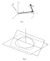
- FIG. 1 represents a particle of mass m in space following a trajectory with a speed ⁇ , in an Oxyz reference system in which it has a vector of position r and a kinetic moment h . It serves to illustrate the physical law on which the invention is based.
- Figure 2 shows a ring on a plane ⁇ and also the same ring on another plane ⁇ ', which has turned relative to the first.
- the axis of rotation goes through a diametrical line of the ring.
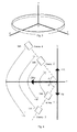
- Figure 3 shows the reference system linked to a ring generic of those used in the mechanism.
- the center O coincides with the center of the ring
- the Z axis coincides with the main axis perpendicular to the plane circumferential of the ring
- the X and Y axes are orthogonal to Z and between them forming a dextrorotatory system and they lie in the circumferential plane way.
- Figure 4 shows the four rings, which form the mechanism, projected onto the ZY plane of an inertial reference system whose axes Z and X are coincide with the reference system linked to the solid exposed in figure 3.
- the rings arranged coaxially are rotated in this plane: the 1 and the 3 by an angle - ⁇ , the 2 and the 4 of an angle + ⁇ .
- the rings of the lower quadrant (1 and 3) have a speed negative spin rotation.
- Those of the upper quadrant (2 and 4) have a speed of positive spin.
- the arrows indicate the nutation rotations performed by the rings under the conditions already indicated.
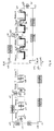
- Figure 5 is a diagram of a device called Inverter Couple. It realizes, as its name suggests, the torque reversal occurring at the following the combined movement of the 4 rings, when necessary. As we will further describe, the operating cycle of the rings produce alternately pairs of opposite signs. This device alternately reverses couples so that there are finally couples of the same sign. For this, the device can be activated (left position) or deactivated (right position). It is consisting of a planetary gear e2, the axis of which includes a rod which can be position on A (left diagram) or on B (right diagram). This rod will allow the Inverter to be enabled or disabled.
- the planetary gear e2 is in contact with an e3 satellite, which also meshes (in the “activated” position) with e1, which is an inner gear.
- the e3 gear has 2 pins which can be introduced into two holes located in the internal gear e1 (position “Disabled”). The operation of this device is explained below.
- Figure 6 shows the diagram of the mechanism of the four crowns which can perform the spin and nutation rotations generated by the object torque of the gyroscopic actuator. It is a projection on the XZ plane of the inertial reference system. We observe the projections of the 4 rings on this plan (their straight sections). We also see the shape of the ring support at means of parts (C1, C2, C3, C4) which are called cradles. They consist of sectors that hold the rings and allow them to slide through them (spin rotation). We can see the kinematic chains that lead to the rings the spin rotations ( ⁇ ) and the nutation rotations (aux) at the corresponding torques.
- Figure 7 is a graph where, on the ordinate, the angulation values of nutation which, at the start, the generic ring and, on the abscissa, the times are indicated. This figure is used to explain the transition that has place when a ring begins its nutation movement.
- Figure 8 is similar to the previous one, but referring to the judgment of the nutation movement of a generic ring.
- Figure 9 is a graph showing the value of the torque generated Ny (t) during a cycle of combined operation of the four rings.
- the cycle consists of two half cycles. In the first, rings 1 and 2 (between 0 and t1) start up, then the rings evolve according to the function of assigned nutation (between t1 and t2) and, finally, they stop (between t2 and ta). In this last interval, rings 3 and 4 start (between 0 and t1 of their half cycle), the second half cycle then begins. Then, they also evolve according to the assigned nutation function (between t1 and 2) and, finally, they stop (between t2 and ta), having thus completed the second half-cycle and completed the operating cycle. Mechanism action will require many consecutive cycles.
- Figure 10 shows a block diagram of the Actuator Gyroscopic. Its explanation is detailed in the paragraph "Description Technical ”.
- the gyroscopic actuator is based on the law of conservation of the angular momentum.
- the definition of the angular momentum of a particle (figure 1) of mass m , in motion at a speed ⁇ with respect to a Newtonian reference system Oxyz, is the value h resulting from the vector product of the vector of the momentum m ⁇ with the particle position vector r .
- the 4 rings have, according to what has been said, two degrees of freedom: spin ( ⁇ ) and nutation ( ⁇ ), the precession ( ⁇ ) being zero at all times.
- the rings When the rings start to work, they perform the same rotation in nutation as that indicated for rings 1 and 2, the cycle being thus completed.
- the rings 3 and 4 also do the same as 1 and 2. More specifically, when first cycle, the rings coming into action in pairs, rotate in nutation and, during the next cycle, undo the rotation in nutation.
- the value of the spin function, expressed by ⁇ (t) is of the type linear, that is why the rings spin in spin at constant speed.
- the nutation function ⁇ (t) must be of the inverse circular type, so that the projection of the torque on the Y axis is constant during the evolution of the rotation of wobble.
- the form of these functions and the pairwise operation of the rings ensure a constant direction torque vector (not the direction, as we comment later), constant module and controllable action time (as long as we will want to), which are part of the conditions mentioned previously, that had to fulfill the gyroscopic actuator.
- Figure 6 shows the diagram of the actuator mechanism gyroscopic with its four rings projected on the XZ plane and the chains kinematics, consisting of gear trains which send the crowns rotation in spin ⁇ and in nutation ⁇ . Thanks to this figure, we can understand the combined operation of the mechanism.
- Ring 2 receives the same spin movement from gear e15 through the chain e16, e17, e18, e19, e21, e22, e23, e24, e25, e26 and e27. This last communicates to ring 2 the spin movement which, in turn, is communicated in opposite direction to ring 1 using e28 and e29 in the same way as that indicated for rings 4 and 3.
- the nutation movement is transmitted independently to pairs of rings 1,2 and 2,3.
- the nutation ⁇ is received through the gear e36 which, by means of the kinematic chain e35, e34, e33, e8 and e7 including the axis is integral with the cradle C2. It is a piece that embraces an area of the ring 2, serving as a support; the ring moves by being tightened by this part (cradle), which will serve to support it and also to force it to rotate nutation ⁇ , even when it will spin spin ⁇ . e7 thus turning in nutation of + ⁇ at - ⁇ , will rotate the cradle C2 together and, consequently, the ring 2. It is understood that ⁇ must not exceed the value of 70 °.
- the nutation movement ⁇ for rings 3 and 4 is received by the gear e14. It is transmitted via the kinematic chain e12, e11, e10 and e9.
- the axis of the latter gear is integral with the cradle C4 which requires the ring 4 to rotate in nutation from + ⁇ to - ⁇ .
- the nutation movement is now transmitted to the ring 3 from 4, by the gears e6, e5, e4 and the cradle C3.
- the torque reverser is shown on the left, in the position "activated” (realizing the torque reversal) and on the right, deactivated (it does not inversion and provides the chassis with the same torque as it receives).
- the reverser is constituted by a first internal gear with two orifices rigidly assembled by its axis to the chassis, an assembly consisting of two gears forming the satellite and the planetary, the latter with two pins and a rod connected to the axis of the planetary gear.
- the operation of the inverter is as follows: when the rod is in position A, the torque reverser is activated and the teeth of the satellite are opposite of the inner gear. The torque of the mechanism is received by the axis of the planet, which, by means of the satellite, reverses the torque which is received by the internal gear. This reverse torque is transmitted to the chassis and, therefore, to the platform where it is located the gyroscopic actuator.
- the transient start-up functions apply to the pair of rings which is in action (1 and 2, or 3 and 4). They will coincide in time with the transient stop functions of the opposite pair of rings (3 and 4, or 1 and 2), so that the pairs produced by each pair (one at start-up and another at the stop) do not give rise, by adding up, to a significant alteration of the couple which is provided by the mechanism. In these situations, there is an overlap in the combined operation of the rings, as can be seen in FIG. 9. This zone is critical to obtain a good functioning of the mechanism, without it there are abrupt behaviors affecting the modulus of the couple Ny (t).
- Figure 10 is a diagram of the actuator architecture gyroscopic, where you can see schematically the parts to which it has been hints during the previous explanation. We see a device not mentioned so far which is Action Control. It is a device for electronic control which gives rise to the actions which must be produced by the motors, in the form of kinematic laws, to generate the desired torques and their duration.
- the engine orders are received by the kinematic chains which cause the rings to move in spin and nutation, thus producing torque.
- the couple then passes through the shock absorber to reduce alterations in the area of overlap of the cycle and, finally, we make it reach the platform in causing its change of orientation.
- this is the last (nutation time) which will essentially be used to increase or decrease the modulus of the vector couple, when necessary. He has the quickest answer because he depends on the actions of the corresponding motors, which generate the kinematic law according to the order received from the Action Control.
- the dependence of the action time of the function of nutation which is implicit in the expression d ⁇ (t) / dt, is inversely proportional; the shorter the nutation action time, the greater the torque produced.
Landscapes
- Engineering & Computer Science (AREA)
- Chemical & Material Sciences (AREA)
- Combustion & Propulsion (AREA)
- Remote Sensing (AREA)
- Radar, Positioning & Navigation (AREA)
- Mechanical Engineering (AREA)
- General Engineering & Computer Science (AREA)
- Aviation & Aerospace Engineering (AREA)
- Physics & Mathematics (AREA)
- General Physics & Mathematics (AREA)
- Control Of Position, Course, Altitude, Or Attitude Of Moving Bodies (AREA)
- Transmission Devices (AREA)
- Motorcycle And Bicycle Frame (AREA)
- Valve Device For Special Equipments (AREA)
- Fuel-Injection Apparatus (AREA)
- Magnetically Actuated Valves (AREA)
Abstract
Description
- Aéronautiques pour des aéronefs à aile fixe, car il peut remplacer les surfaces de contrôle aérodynamiques des aéronefs (ailerons, gouvernails, etc.) en réalisant les rotations en tangage, roulis ou embardée avec l'actionneur gyroscopique.
- Hélicoptères, grâce au remplacement du rotor de queue qui génère le couple de compensation du couple de réaction dû au rotor principal. L'actionneur se charge de produire ce couple de compensation et permet la conduite de l'hélicoptère en embardée.
- Navales, car il permet le remplacement des gouvernails des bateaux et des embarcations, et d'effectuer des manoeuvres avec l'actionneur gyroscopique.
- Stabilisation de véhicules terrestres (automobiles, camions, autocars et trains), car il peut produire des couples s'opposant aux couples de capotage dans les changements de direction lorsque le véhicule est en marche.
- Aéronautique. La gouverne des aéronefs à aile fixe en cas de
tangage, de roulis et d'embardée se fait grâce aux surfaces aérodynamiques de
contrôle qui sont installées sur les ailes, les stabilisateurs et le gouvernail de queue.
Quoiqu'il existe de nombreuses variantes quant à la configuration de base, cette
modalité de gouverne est basée sur la résistance aérodynamique que produisent de
telles surfaces, au moment de faire varier leur disposition initiale afin d'effectuer la
manoeuvre demandée. Au moyen de la résistance aérodynamique qu'elles
produisent, il apparaít des forces et des moments résultants sur l'ensemble structural
de l'aéronef, ce qui permet ainsi de réaliser la manoeuvre recherchée.
L'actionneur gyroscopique produit une série de couples sur
l'ensemble structural de l'aéronef, de sorte que ce dernier soit obligé de changer son
orientation sur les trois axes du système de référence liée à celui-ci, produisant ainsi
les rotations en tangage, roulis et embardée qui permettent la manoeuvre demandée.Le besoin est évident, car l'actionneur gyroscopique présente les
avantages suivants par rapport au procédé conventionnel (surfaces aérodynamiques):
- Il n'y a pas de résistances aérodynamiques associées à son propre fonctionnement s'accompagnant d'une consommation énergétique ajoutée.

- On réussit à éliminer tous les mécanismes associés aux surfaces de contrôle actuelles, ainsi qu'à simplifier l'architecture extérieure de l'aéronef (ailes et stabilisateurs). Ceci aura pour conséquence une plus grande capacité de charge payée.
 En ce qui concerne l'état de la technique, il faut indiquer que
certains types d'aéronefs à aile fixe, plus concrètement certains modèles d'avions de
combat, peuvent renforcer les manoeuvres des surfaces de contrôle grâce à la
variation du vecteur de poussée qui a lieu dans les tuyères des moteurs. Ceci est
obtenu grâce à une déviation des gaz de sortie dans la tuyère elle-même qui est
conçue pour varier sa géométrie de façon appropriée.
En ce qui concerne l'état de la technique, il faut indiquer que
certains types d'aéronefs à aile fixe, plus concrètement certains modèles d'avions de
combat, peuvent renforcer les manoeuvres des surfaces de contrôle grâce à la
variation du vecteur de poussée qui a lieu dans les tuyères des moteurs. Ceci est
obtenu grâce à une déviation des gaz de sortie dans la tuyère elle-même qui est
conçue pour varier sa géométrie de façon appropriée. - Hélicoptères. Comme on le sait, l'hélicoptère est un type
d'aéronef à aile pivotante qui a une hélice principale actionnée par un moteur, avec
laquelle il peut se soutenir dans l'air et, en même temps, se déplacer. Le couple qui
fait fonctionner l'hélice principale crée un autre couple de signe opposé qui ferait
tourner la cellule de vol dans le sens contraire, si ce n'était du fait de plusieurs
solutions qui ont été trouvées jusqu'à présent. Parmi les plus importantes, figurent les
suivantes (Modern Fighting Helicopters, Bill Gunston and Mike Spick, 1998
Greenwich Editions):
- Hélice compensatrice de queue (Penny ― farthing). Un exemple de cette configuration est le Lynx. C'est la plus commune. Le couple compensateur est généré par une hélice à la queue du fuselage, qui permet également de contrôler l'orientation en embardée de l'aéronef.

- Rotors en tandem (Twin tandem). Exemple: le Chinook. Cette configuration possède deux rotors principaux, qui sont dans le même plan et se déplaçant en tournant en sens contraire, ce qui permet ainsi de compenser leurs couples respectifs.

- Rotors d'un côté à l'autre (Twin side). Exemple: le V-12. Les deux rotors sont situés des deux côtés du fuselage et tournent en sens contraire à des régimes tels que les couples sont compensés.

- Rotors d'un côté à l'autre entrecroisés (Twin intermeshing). Exemple: HH-43. C'est une variante du précédent dans laquelle les rotors s'approchent jusqu'à ce que les pales s'entrecroisent, ce qui permet ainsi une configuration plus compacte.

- Rotors coaxiaux (Twin coaxial). Exemple: Ka-25. Les axes des deux rotors sont coaxiaux et produisent des couples identiques et de signe contraire.


- Navals. Sur n'importe quel type de bateau ou embarcation, on utilise le gouvernail pour effectuer la manoeuvre qui produit, en définitive, de la même façon que ce qui arrive avec les aéronefs, un moment résultant sur la structure, en permettant de l'orienter dans la direction voulue.
- Véhicules terrestres. L'application la plus immédiate prévue dans ce domaine est la stabilisation des véhicules quand ils se déplacent. Dans le cas des automobiles (autocars et camions aussi), il y a actuellement deux types de dispositifs qui confèrent une stabilité au véhicule, lorsqu'il faut faire face à un changement de direction suffisamment accusé pour provoquer un couple de retournement considérable sur l'ensemble structural. De tels dispositifs sont les barres stabilisatrices et les systèmes d'amortissement actif. Dans les deux cas, on recherche un accroissement de la rigidité de la suspension du véhicule du côté du véhicule où se produit le pivotement par retournement et une diminution sur le côté opposé, de sorte que le véhicule ait tendance à basculer dans le sens contraire à celui du retournement et qu'ainsi l'instabilité soit compensée par la propre masse déplacée. À titre de référence, énumérons les brevets suivants: US005876148, US004930807, US004550926, US005876148, US004345661, GB2039834A, DE4116837, JP57182505.

- Inertie des anneaux. Cela implique la géométrie (dimensions) et le matériel qui constitue les anneaux.
- Vitesse de rotation en spin des anneaux.
- Temps d'action de la fonction de nutation (ta sur la figure 9) dans chaque paire coordonnée d'anneaux.
Claims (13)
- Actionneur gyroscopique, de ceux qui servent à produire un couple ou un moment sur la plateforme sur laquelle il est situé, grâce à l'application de la loi de conservation du moment cinétique dans son mécanisme interne, se caractérisant par le fait que:a) le vecteur du couple a une direction et un sens fixes dans le système de référence inertiel, une fois qu'il est produit,b) le module du couple fourni à la plateforme a une valeur constante ou une valeur moyenne avec une perturbation cyclique inférieure à 20% de cette valeur moyenne,c) la durée du couple dans les conditions précédentes est illimitée tant que les paramètres qui le produisent ne sont pas changés intentionnellement, auquel cas l'actionneur peut réaliser, en fonction de la demande, l'une quelconque des options suivantes:cesser de fournir un couple,augmenter ou diminuer la valeur du module,changer la direction et/ou le sens du vecteur couple.
- Actionneur gyroscopique selon la revendication antérieure, se caractérisant par le fait de produire le couple dans les conditions signalées, dispose d'un mécanisme de base formé par quatre anneaux disposés concentriquement qui agissent, chacun d'entre eux, au moyen d'une rotation en spin et rotations coordonnées en nutation par paires.
- Actionneur gyroscopique selon revendications antérieures, se caracérisant par le fait que les anneaux concentriques qui constituent le mécanisme de base ont tous les mêmes moments principaux d'inertie.
- Actionneur gyroscopique selon revendications antérieures, se caractérisant par le fait que la fonction de la rotation de spin est linéaire et fournit une vitesse de rotation constante et que la fonction de la rotation de nutation est du type asin(pt±q), où t est la variable indépendante temps et p, q deux constantes, de façon à permettre l'obtention d'un module du vecteur couple constant dans le mécanisme.
- Actionneur gyroscopique selon revendications antérieures, se caractérisant par le fait que la rotation en nutation définie par la fonction de la revendication antérieure envisage une fonction additionnelle pour le démarrage en utation et une autre supplémentaire pour l'arrêt, qui agissent comme fonctions transitoires en mettant les anneaux dans les condtions exigées par le mouvement en nutation.
- Actionneur gyroscopique selon revendications antérieures, se caractérisant par le fait que les mouvements de spin et de nutation qui arrivent aux anneaux viennent d'un dispositif générateur de puissance mécanique à travers des chaínes cinématiques.
- Actionneur gyroscopique selon revendications antérieures, se caractérisant par le fait qu'il dispose d'un dispositif pour inverser le couple qu'il produit pour la plateforme où il est installé.
- Actionneur gyroscopique selon revendications antérieures, se caractérisant par le fait qu'il peut être utilisé sur des plateformes navales, afin d'arriver à la gouverne de celles-ci en tangage, roulis et embardée, les gouvernails ou autres systèmes de manoeuvre pouvant être remplacés, ainsi que pour obtenir la stabilisation de la plateforme elle-même.
- Actionneur gyroscopique selon la première à la septième revendication, se caractérisant par le fait qu'il peut être utilisé sur des aéronefs à aile fixe conférant la possibilité de gouverne en tangage, roulis et embardée.
- Actionneur gyroscopique selon la première à la septième revendication, se caractérisant par le fait qu'il peut être utilisé sur des hélicoptères du type actuel à hélice de compensation dans la queue, permettant d'éliminer le rotor de queue, ainsi que sa structure portante et ses mécanismes associés, conférant le contrôle et la gouverne en embardée.
- Actionneur gyroscopique selon la première à la septième revendication, se caractérisant par le fait qu'il peut être utilisé sur des véhicules automobiles terrestres pour corriger l'instabilité dynamique des châssis au moment d'effectuer des manoeuvres avec changements de direction, grâce à la production du couple approprié pour qu'il compense l'instabilité.
- Actionneur gyroscopique selon la première à la septième revendication, se caractérisant par le fait qu'il peut être utilisé sur des trains, aussi bien sur des voitures motrices que sur des wagons, pour obtenir la stabilité dynamique de ce type de véhicules.
- Actionneur gyroscopique selon la première à la septième revendication, se caractérisant par le fait qu'il peut être utilisé sur des plateformes aérospatiales, pour en changer l'attitude avec des couples qui peuvent atteindre des valeurs de l'ordre de 103 N-m.
Applications Claiming Priority (3)
| Application Number | Priority Date | Filing Date | Title |
|---|---|---|---|
| ES200102290 | 2001-10-17 | ||
| ES200102290A ES2188404B1 (es) | 2001-10-17 | 2001-10-17 | Actuador giroscopico. |
| PCT/ES2002/000482 WO2003042632A1 (fr) | 2001-10-17 | 2002-10-11 | Verin gyroscopique |
Publications (2)
| Publication Number | Publication Date |
|---|---|
| EP1452830A1 true EP1452830A1 (fr) | 2004-09-01 |
| EP1452830B1 EP1452830B1 (fr) | 2010-08-18 |
Family
ID=8499195
Family Applications (1)
| Application Number | Title | Priority Date | Filing Date |
|---|---|---|---|
| EP02779585A Expired - Lifetime EP1452830B1 (fr) | 2001-10-17 | 2002-10-11 | Verin gyroscopique |
Country Status (8)
| Country | Link |
|---|---|
| US (1) | US7051608B2 (fr) |
| EP (1) | EP1452830B1 (fr) |
| JP (1) | JP4447911B2 (fr) |
| AT (1) | ATE478323T1 (fr) |
| DE (1) | DE60237390D1 (fr) |
| ES (1) | ES2188404B1 (fr) |
| RU (1) | RU2295705C2 (fr) |
| WO (1) | WO2003042632A1 (fr) |
Cited By (1)
| Publication number | Priority date | Publication date | Assignee | Title |
|---|---|---|---|---|
| WO2008044097A1 (fr) * | 2006-10-10 | 2008-04-17 | Erke Erke Arastirmalari Ve Muhendislik A.S. | Appareil gyroscopique |
Families Citing this family (12)
| Publication number | Priority date | Publication date | Assignee | Title |
|---|---|---|---|---|
| US7470217B2 (en) * | 2004-09-21 | 2008-12-30 | Jones-Glaser Danielle E | Grip strength device |
| US7520466B2 (en) * | 2005-03-17 | 2009-04-21 | Nicolae Bostan | Gyro-stabilized air vehicle |
| JP2009528217A (ja) * | 2006-02-28 | 2009-08-06 | アドバンスド ダイナミック システムズ,ソシエダド リミタダ | 人工衛星を制御するためのジャイロアクチュエータ |
| US7554283B2 (en) * | 2007-06-14 | 2009-06-30 | Shahriar Yazdani Damavandi | Non-reaction torque drive |
| WO2011100482A2 (fr) * | 2010-02-10 | 2011-08-18 | Scott Gregory Dietz | Appareil motorisé et dispositif d'application de moment |
| US9124150B2 (en) * | 2013-07-12 | 2015-09-01 | The Boeing Company | Active-active redundant motor gear system |
| US9612117B2 (en) | 2014-07-10 | 2017-04-04 | Honeywell International Inc. | Integrated reaction wheel assembly arrays and multi-rotor chassis suitable for usage therein |
| US10737770B2 (en) | 2015-02-23 | 2020-08-11 | Arif Mir Jalal ogly PASHAYEV | Method and device for increasing the stability and maneuverability of unmanned aerial vehicles (UAV) using a gyroscopic effect |
| WO2017105293A1 (fr) * | 2015-12-14 | 2017-06-22 | Игорь Викторович РЯДЧИКОВ | Dispositif pour stabiliser dans l'espace un corps en 3d avec une compensation de force des influences de déviation |
| EA030859B1 (ru) * | 2016-02-25 | 2018-10-31 | Национальная Академия Авиации | Способ и устройство повышения стабилизации и маневренности беспилотных летательных аппаратов (бла) с применением гироскопического эффекта |
| US12206315B1 (en) * | 2022-06-30 | 2025-01-21 | James F. Murray, III | Gravitational torque amplifier |
| US12529361B2 (en) * | 2022-10-22 | 2026-01-20 | Douglas C Wyatt | Frameshift generator |
Family Cites Families (34)
| Publication number | Priority date | Publication date | Assignee | Title |
|---|---|---|---|---|
| US2158180A (en) * | 1936-11-09 | 1939-05-16 | Robert H Goddard | Gyroscopic steering apparatus |
| US2813430A (en) * | 1954-06-02 | 1957-11-19 | Control Instr Company | Latitude correction systems for stable element |
| US2856142A (en) * | 1956-07-18 | 1958-10-14 | Gen Electric | Orientation control for a space vehicle |
| US2857122A (en) * | 1956-07-18 | 1958-10-21 | Gen Electric | Attitude control system |
| US3336811A (en) * | 1964-05-06 | 1967-08-22 | Sperry Rand Corp | Antifriction support mechanism for gyroscopes |
| US3691853A (en) * | 1970-07-27 | 1972-09-19 | North American Rockwell | Torque generator |
| US3702569A (en) * | 1970-11-19 | 1972-11-14 | Singer Co | System for eliminating gyro on-off drift effects |
| US3741500A (en) * | 1971-04-21 | 1973-06-26 | Sperry Rand Corp | A cmg fine attitude control system |
| JPS5914367B2 (ja) * | 1978-06-08 | 1984-04-04 | 本田技研工業株式会社 | 車輌の懸架装置 |
| US4361055A (en) * | 1980-05-19 | 1982-11-30 | Juris Murnieks | Torque converter |
| JPS57182505A (en) | 1981-05-01 | 1982-11-10 | Kayaba Ind Co Ltd | Antiroll system of vehicle |
| US4863404A (en) * | 1982-12-16 | 1989-09-05 | Salo Eric A | Jet propulsion and stabilization means for ships |
| US4550926A (en) * | 1984-03-28 | 1985-11-05 | Macisaac William L | Vehicle suspension system |
| CH665808A5 (de) | 1984-04-27 | 1988-06-15 | Sig Schweiz Industrieges | Schienenfahrzeug. |
| DE3523160A1 (de) * | 1985-06-28 | 1987-01-08 | Peter Dr Kuemmel | Kaskadenschubpraezessor |
| GB8728712D0 (en) * | 1987-12-09 | 1988-01-27 | Rouse J G | Lifting body |
| FR2625711B1 (fr) * | 1988-01-12 | 1992-04-24 | Peugeot | Dispositif de suspension hydropneumatique semi-active et vehicule automobile equipe de ce dispositif |
| US4817550A (en) * | 1988-01-20 | 1989-04-04 | Gutsche Gunter E | Stabilizing system for vehicles and method for using same |
| US4951514A (en) * | 1988-09-09 | 1990-08-28 | Daniel Gubin | Dual gyroscopic stabilizer |
| GB2225424B (en) * | 1988-11-23 | 1993-07-07 | Paul Chester Eyles | Gyroscopic apparatus |
| US5112012A (en) * | 1989-10-26 | 1992-05-12 | Yuan Mark S | Tilting momentum wheel for spacecraft |
| DE4017474A1 (de) * | 1990-05-31 | 1991-12-05 | Eckhard Dr Kaufmann | Apparat zur erzeugung einer mechanischen kraft |
| DE4020888A1 (de) * | 1990-06-29 | 1992-01-02 | Peter Dr Kuemmel | Kaskadenrotor, 3-dimensional rotierende kreiselmasse mit synchroner drehzahl von gier- und nickachse |
| DE4116837A1 (de) | 1990-09-21 | 1992-03-26 | Hoesch Ag | Drehstab-stabilisator |
| SU1810756A1 (ru) * | 1991-03-21 | 1993-04-23 | Miasskij Elektromekhanicheskij | Устройство для изменения уг-. лов отклонения подвижного объекта |
| DE4243273A1 (de) * | 1992-10-27 | 1994-04-28 | Teldix Gmbh | Einrichtung zum Schwenken eines Flugkörpers, mit zwei Kreiseln |
| US5573265A (en) * | 1993-11-05 | 1996-11-12 | Fichtel & Sachs Ag | Stabilizer system for a motor vehicle suspension system with a rotary actuator |
| US5931421A (en) * | 1995-08-11 | 1999-08-03 | Daimler-Benz Aerospace Ag | Arrangement for attitude control and stabilization of a three axes stabilized spacecraft |
| DE19543690C2 (de) * | 1995-11-23 | 2001-04-19 | Trw Fahrwerksyst Gmbh & Co | Verbindung eines Stabilisators mit der Radaufhängung eines Kraftfahrzeuges |
| US5826829A (en) * | 1996-07-15 | 1998-10-27 | Space Systems/Loral Inc. | Spacecraft control system with a trihedral momentum bias wheel configuration |
| US6135392A (en) * | 1998-09-29 | 2000-10-24 | Hughes Electronics Corporation | Spacecraft attitude control actuator and method |
| US6568291B1 (en) * | 2000-10-05 | 2003-05-27 | William E. Inman | Shaftless gyrostabilizer |
| US6705174B2 (en) * | 2001-03-28 | 2004-03-16 | Ganid Productions, Llc | Apparatus and method for gyroscopic propulsion |
| US6729580B2 (en) * | 2001-04-05 | 2004-05-04 | Northrop Grumman Corporation | Method and system for directing an object using gyroscopes |
-
2001
- 2001-10-17 ES ES200102290A patent/ES2188404B1/es not_active Expired - Fee Related
-
2002
- 2002-10-11 DE DE60237390T patent/DE60237390D1/de not_active Expired - Lifetime
- 2002-10-11 JP JP2003544417A patent/JP4447911B2/ja not_active Expired - Fee Related
- 2002-10-11 WO PCT/ES2002/000482 patent/WO2003042632A1/fr not_active Ceased
- 2002-10-11 AT AT02779585T patent/ATE478323T1/de not_active IP Right Cessation
- 2002-10-11 EP EP02779585A patent/EP1452830B1/fr not_active Expired - Lifetime
- 2002-10-11 RU RU2004114847/28A patent/RU2295705C2/ru not_active IP Right Cessation
- 2002-10-11 US US10/487,120 patent/US7051608B2/en not_active Expired - Fee Related
Non-Patent Citations (1)
| Title |
|---|
| See references of WO03042632A1 * |
Cited By (5)
| Publication number | Priority date | Publication date | Assignee | Title |
|---|---|---|---|---|
| WO2008044097A1 (fr) * | 2006-10-10 | 2008-04-17 | Erke Erke Arastirmalari Ve Muhendislik A.S. | Appareil gyroscopique |
| EA014602B1 (ru) * | 2006-10-10 | 2010-12-30 | Эрке Эрке Араштырмалары Ве Мюхендислик А. Ш. | Гироскопическое устройство |
| US8047090B2 (en) | 2006-10-10 | 2011-11-01 | Erke Erke Arastirmalari Ve Muhendislik A.S. | Method of generating rotation about an output axis and motor for generating rotation about an output axis |
| KR101130896B1 (ko) * | 2006-10-10 | 2012-03-28 | 얼커 얼커 알라스틸마라리 베 뮤헨디슬릭 에이.에스. | 출력축을 중심으로 회전을 발생시키는 방법 및 모터 |
| AP2540A (en) * | 2006-10-10 | 2012-12-20 | Erke Erke Arastirmalari Ve Muhandislik As | Method of generating rotation about an output axisand motor for generating rotation about an output axis |
Also Published As
| Publication number | Publication date |
|---|---|
| JP2005539202A (ja) | 2005-12-22 |
| ATE478323T1 (de) | 2010-09-15 |
| DE60237390D1 (de) | 2010-09-30 |
| US7051608B2 (en) | 2006-05-30 |
| US20040173037A1 (en) | 2004-09-09 |
| ES2188404B1 (es) | 2004-10-16 |
| WO2003042632A1 (fr) | 2003-05-22 |
| RU2004114847A (ru) | 2005-03-27 |
| RU2295705C2 (ru) | 2007-03-20 |
| EP1452830B1 (fr) | 2010-08-18 |
| ES2188404A1 (es) | 2003-06-16 |
| JP4447911B2 (ja) | 2010-04-07 |
Similar Documents
| Publication | Publication Date | Title |
|---|---|---|
| EP1452830B1 (fr) | Verin gyroscopique | |
| CA2255602C (fr) | Aerodyne a decollage et atterrissage verticaux | |
| EP1680648B1 (fr) | Controle d'attitude de satellites en particulier agiles a nombre reduit de gyrodynes | |
| HK1204359A1 (en) | Gyroscope stabilization in two-wheeled vehicles | |
| FR2973335A1 (fr) | Micro/nano vehicule aerien commande a distance comportant un systeme de roulage au sol, de decollage vertical et d'atterrissage | |
| FR2786283A1 (fr) | Procede et dispositif de pilotage de l'attitude d'un satellite | |
| EP2542459A1 (fr) | Véhicule électrique comportant au moins trois roues | |
| US20100307290A1 (en) | Apparatus, system and method for gyroscopic propulsion and/or steering | |
| CA2382879A1 (fr) | Perfectionnements aux aeronefs convertibles a rotors basculants | |
| CA2057731A1 (fr) | Procede de reacquisition d'attitude par reconnaissance d'etoile pour satellite stabilise 3-axes | |
| EP1165369A1 (fr) | Helicoptere a pilotage pendulaire a haute stabilite et a grande manoeuvrabilite | |
| EP0696252B1 (fr) | Satellite artificiel muni de gouvernes aerodynamiques d'orientation | |
| FR2924095A1 (fr) | Actionneur a transfert de moment cinetique pour le controle d'attitude d'un engin spatial | |
| EP2942287B1 (fr) | Procédé de commande d'un système de contrôle d'attitude et système de contrôle d'attitude d'un véhicule spatial | |
| EP3538441B1 (fr) | Projectile destiné à l'amortissement d'un engin spatial et vehicule spatial d'acheminement correspondant | |
| EP2668100B1 (fr) | Procédé et système de pilotage d'un engin volant à propulseur arrière | |
| EP1993017A1 (fr) | Actionneur gyroscopique permettant de commander des satellites | |
| Dharshan et al. | Design of self balancing system for two-wheeler | |
| KR20250121225A (ko) | 각운동량 보존의 법칙을 이용한 공중부양장치 | |
| BE644720A (fr) | ||
| BE379719A (fr) | ||
| WO2007084092A1 (fr) | Procédé permettant de générer une force de poussée à l'aide des forces de coriolis, dispositif gyroturbine destiné à sa mise en oeuvre et moyen de transport faisant appel à un dispositif gyroturbine | |
| FR2927279A1 (fr) | Stabilisation gyroscopique active | |
| HK1182673A (en) | Gyroscopic stabilized vehicle |
Legal Events
| Date | Code | Title | Description |
|---|---|---|---|
| PUAI | Public reference made under article 153(3) epc to a published international application that has entered the european phase |
Free format text: ORIGINAL CODE: 0009012 |
|
| 17P | Request for examination filed |
Effective date: 20040210 |
|
| AK | Designated contracting states |
Kind code of ref document: A1 Designated state(s): AT BE BG CH CY CZ DE DK EE ES FI FR GB GR IE IT LI LU MC NL PT SE SK TR |
|
| GRAP | Despatch of communication of intention to grant a patent |
Free format text: ORIGINAL CODE: EPIDOSNIGR1 |
|
| GRAS | Grant fee paid |
Free format text: ORIGINAL CODE: EPIDOSNIGR3 |
|
| GRAA | (expected) grant |
Free format text: ORIGINAL CODE: 0009210 |
|
| RAP1 | Party data changed (applicant data changed or rights of an application transferred) |
Owner name: BUSINESS EVERYWHERE SL |
|
| AK | Designated contracting states |
Kind code of ref document: B1 Designated state(s): AT BE BG CH CY CZ DE DK EE ES FI FR GB GR IE IT LI LU MC NL PT SE SK TR |
|
| REG | Reference to a national code |
Ref country code: GB Ref legal event code: FG4D Free format text: NOT ENGLISH |
|
| REG | Reference to a national code |
Ref country code: CH Ref legal event code: EP |
|
| REG | Reference to a national code |
Ref country code: IE Ref legal event code: FG4D Free format text: LANGUAGE OF EP DOCUMENT: FRENCH |
|
| REF | Corresponds to: |
Ref document number: 60237390 Country of ref document: DE Date of ref document: 20100930 Kind code of ref document: P |
|
| REG | Reference to a national code |
Ref country code: NL Ref legal event code: T3 |
|
| PG25 | Lapsed in a contracting state [announced via postgrant information from national office to epo] |
Ref country code: FI Free format text: LAPSE BECAUSE OF FAILURE TO SUBMIT A TRANSLATION OF THE DESCRIPTION OR TO PAY THE FEE WITHIN THE PRESCRIBED TIME-LIMIT Effective date: 20100818 Ref country code: AT Free format text: LAPSE BECAUSE OF FAILURE TO SUBMIT A TRANSLATION OF THE DESCRIPTION OR TO PAY THE FEE WITHIN THE PRESCRIBED TIME-LIMIT Effective date: 20100818 |
|
| PGFP | Annual fee paid to national office [announced via postgrant information from national office to epo] |
Ref country code: FR Payment date: 20101230 Year of fee payment: 9 Ref country code: NL Payment date: 20101130 Year of fee payment: 9 |
|
| PG25 | Lapsed in a contracting state [announced via postgrant information from national office to epo] |
Ref country code: BG Free format text: LAPSE BECAUSE OF FAILURE TO SUBMIT A TRANSLATION OF THE DESCRIPTION OR TO PAY THE FEE WITHIN THE PRESCRIBED TIME-LIMIT Effective date: 20101118 Ref country code: PT Free format text: LAPSE BECAUSE OF FAILURE TO SUBMIT A TRANSLATION OF THE DESCRIPTION OR TO PAY THE FEE WITHIN THE PRESCRIBED TIME-LIMIT Effective date: 20101220 Ref country code: CY Free format text: LAPSE BECAUSE OF FAILURE TO SUBMIT A TRANSLATION OF THE DESCRIPTION OR TO PAY THE FEE WITHIN THE PRESCRIBED TIME-LIMIT Effective date: 20100818 |
|
| REG | Reference to a national code |
Ref country code: IE Ref legal event code: FD4D |
|
| PG25 | Lapsed in a contracting state [announced via postgrant information from national office to epo] |
Ref country code: SE Free format text: LAPSE BECAUSE OF FAILURE TO SUBMIT A TRANSLATION OF THE DESCRIPTION OR TO PAY THE FEE WITHIN THE PRESCRIBED TIME-LIMIT Effective date: 20100818 |
|
| PGFP | Annual fee paid to national office [announced via postgrant information from national office to epo] |
Ref country code: GB Payment date: 20101111 Year of fee payment: 9 |
|
| PG25 | Lapsed in a contracting state [announced via postgrant information from national office to epo] |
Ref country code: DK Free format text: LAPSE BECAUSE OF FAILURE TO SUBMIT A TRANSLATION OF THE DESCRIPTION OR TO PAY THE FEE WITHIN THE PRESCRIBED TIME-LIMIT Effective date: 20100818 Ref country code: IE Free format text: LAPSE BECAUSE OF FAILURE TO SUBMIT A TRANSLATION OF THE DESCRIPTION OR TO PAY THE FEE WITHIN THE PRESCRIBED TIME-LIMIT Effective date: 20100818 |
|
| BERE | Be: lapsed |
Owner name: BUSINESS EVERYWHERE SL Effective date: 20101031 |
|
| PG25 | Lapsed in a contracting state [announced via postgrant information from national office to epo] |
Ref country code: EE Free format text: LAPSE BECAUSE OF FAILURE TO SUBMIT A TRANSLATION OF THE DESCRIPTION OR TO PAY THE FEE WITHIN THE PRESCRIBED TIME-LIMIT Effective date: 20100818 Ref country code: SK Free format text: LAPSE BECAUSE OF FAILURE TO SUBMIT A TRANSLATION OF THE DESCRIPTION OR TO PAY THE FEE WITHIN THE PRESCRIBED TIME-LIMIT Effective date: 20100818 Ref country code: MC Free format text: LAPSE BECAUSE OF NON-PAYMENT OF DUE FEES Effective date: 20101031 Ref country code: CZ Free format text: LAPSE BECAUSE OF FAILURE TO SUBMIT A TRANSLATION OF THE DESCRIPTION OR TO PAY THE FEE WITHIN THE PRESCRIBED TIME-LIMIT Effective date: 20100818 |
|
| PGFP | Annual fee paid to national office [announced via postgrant information from national office to epo] |
Ref country code: DE Payment date: 20101210 Year of fee payment: 9 |
|
| REG | Reference to a national code |
Ref country code: CH Ref legal event code: PL |
|
| PLBE | No opposition filed within time limit |
Free format text: ORIGINAL CODE: 0009261 |
|
| STAA | Information on the status of an ep patent application or granted ep patent |
Free format text: STATUS: NO OPPOSITION FILED WITHIN TIME LIMIT |
|
| PG25 | Lapsed in a contracting state [announced via postgrant information from national office to epo] |
Ref country code: ES Free format text: LAPSE BECAUSE OF FAILURE TO SUBMIT A TRANSLATION OF THE DESCRIPTION OR TO PAY THE FEE WITHIN THE PRESCRIBED TIME-LIMIT Effective date: 20101129 |
|
| 26N | No opposition filed |
Effective date: 20110519 |
|
| PG25 | Lapsed in a contracting state [announced via postgrant information from national office to epo] |
Ref country code: LI Free format text: LAPSE BECAUSE OF NON-PAYMENT OF DUE FEES Effective date: 20101031 Ref country code: CH Free format text: LAPSE BECAUSE OF NON-PAYMENT OF DUE FEES Effective date: 20101031 |
|
| PGFP | Annual fee paid to national office [announced via postgrant information from national office to epo] |
Ref country code: IT Payment date: 20101216 Year of fee payment: 9 |
|
| PG25 | Lapsed in a contracting state [announced via postgrant information from national office to epo] |
Ref country code: BE Free format text: LAPSE BECAUSE OF NON-PAYMENT OF DUE FEES Effective date: 20101031 |
|
| REG | Reference to a national code |
Ref country code: DE Ref legal event code: R097 Ref document number: 60237390 Country of ref document: DE Effective date: 20110519 |
|
| REG | Reference to a national code |
Ref country code: NL Ref legal event code: V1 Effective date: 20120501 |
|
| GBPC | Gb: european patent ceased through non-payment of renewal fee |
Effective date: 20111011 |
|
| REG | Reference to a national code |
Ref country code: FR Ref legal event code: ST Effective date: 20120629 |
|
| PG25 | Lapsed in a contracting state [announced via postgrant information from national office to epo] |
Ref country code: NL Free format text: LAPSE BECAUSE OF NON-PAYMENT OF DUE FEES Effective date: 20120501 Ref country code: DE Free format text: LAPSE BECAUSE OF NON-PAYMENT OF DUE FEES Effective date: 20120501 |
|
| REG | Reference to a national code |
Ref country code: DE Ref legal event code: R119 Ref document number: 60237390 Country of ref document: DE Effective date: 20120501 |
|
| PG25 | Lapsed in a contracting state [announced via postgrant information from national office to epo] |
Ref country code: FR Free format text: LAPSE BECAUSE OF NON-PAYMENT OF DUE FEES Effective date: 20111102 Ref country code: GB Free format text: LAPSE BECAUSE OF NON-PAYMENT OF DUE FEES Effective date: 20111011 Ref country code: IT Free format text: LAPSE BECAUSE OF NON-PAYMENT OF DUE FEES Effective date: 20111011 |
|
| PG25 | Lapsed in a contracting state [announced via postgrant information from national office to epo] |
Ref country code: LU Free format text: LAPSE BECAUSE OF NON-PAYMENT OF DUE FEES Effective date: 20101011 |
|
| PG25 | Lapsed in a contracting state [announced via postgrant information from national office to epo] |
Ref country code: TR Free format text: LAPSE BECAUSE OF FAILURE TO SUBMIT A TRANSLATION OF THE DESCRIPTION OR TO PAY THE FEE WITHIN THE PRESCRIBED TIME-LIMIT Effective date: 20100818 |
|
| PG25 | Lapsed in a contracting state [announced via postgrant information from national office to epo] |
Ref country code: GR Free format text: LAPSE BECAUSE OF FAILURE TO SUBMIT A TRANSLATION OF THE DESCRIPTION OR TO PAY THE FEE WITHIN THE PRESCRIBED TIME-LIMIT Effective date: 20100818 |