EP1452785B1 - Kugelhahn - Google Patents
Kugelhahn Download PDFInfo
- Publication number
- EP1452785B1 EP1452785B1 EP04003704A EP04003704A EP1452785B1 EP 1452785 B1 EP1452785 B1 EP 1452785B1 EP 04003704 A EP04003704 A EP 04003704A EP 04003704 A EP04003704 A EP 04003704A EP 1452785 B1 EP1452785 B1 EP 1452785B1
- Authority
- EP
- European Patent Office
- Prior art keywords
- seal
- blocking element
- ball valve
- switching
- valve according
- Prior art date
- Legal status (The legal status is an assumption and is not a legal conclusion. Google has not performed a legal analysis and makes no representation as to the accuracy of the status listed.)
- Expired - Lifetime
Links
- 238000007789 sealing Methods 0.000 claims abstract description 63
- 238000003825 pressing Methods 0.000 claims description 14
- 230000009471 action Effects 0.000 claims description 9
- 238000006073 displacement reaction Methods 0.000 claims description 4
- 230000009969 flowable effect Effects 0.000 claims description 3
- 239000012530 fluid Substances 0.000 claims description 3
- 230000000903 blocking effect Effects 0.000 claims 27
- 230000002349 favourable effect Effects 0.000 description 7
- 238000010276 construction Methods 0.000 description 5
- 238000009434 installation Methods 0.000 description 4
- 230000008901 benefit Effects 0.000 description 2
- 238000010586 diagram Methods 0.000 description 2
- 230000000694 effects Effects 0.000 description 2
- 239000000463 material Substances 0.000 description 2
- 230000005540 biological transmission Effects 0.000 description 1
- 230000000295 complement effect Effects 0.000 description 1
- 210000003746 feather Anatomy 0.000 description 1
- 230000006872 improvement Effects 0.000 description 1
- 239000007788 liquid Substances 0.000 description 1
- 238000004519 manufacturing process Methods 0.000 description 1
- 230000001404 mediated effect Effects 0.000 description 1
- 238000000034 method Methods 0.000 description 1
- 230000009467 reduction Effects 0.000 description 1
- 238000009491 slugging Methods 0.000 description 1
- 239000007787 solid Substances 0.000 description 1
- 230000007704 transition Effects 0.000 description 1
Images
Classifications
-
- F—MECHANICAL ENGINEERING; LIGHTING; HEATING; WEAPONS; BLASTING
- F16—ENGINEERING ELEMENTS AND UNITS; GENERAL MEASURES FOR PRODUCING AND MAINTAINING EFFECTIVE FUNCTIONING OF MACHINES OR INSTALLATIONS; THERMAL INSULATION IN GENERAL
- F16K—VALVES; TAPS; COCKS; ACTUATING-FLOATS; DEVICES FOR VENTING OR AERATING
- F16K5/00—Plug valves; Taps or cocks comprising only cut-off apparatus having at least one of the sealing faces shaped as a more or less complete surface of a solid of revolution, the opening and closing movement being predominantly rotary
- F16K5/06—Plug valves; Taps or cocks comprising only cut-off apparatus having at least one of the sealing faces shaped as a more or less complete surface of a solid of revolution, the opening and closing movement being predominantly rotary with plugs having spherical surfaces; Packings therefor
- F16K5/0663—Packings
- F16K5/0673—Composite packings
- F16K5/0678—Composite packings in which only one of the components of the composite packing is contacting the plug
-
- F—MECHANICAL ENGINEERING; LIGHTING; HEATING; WEAPONS; BLASTING
- F16—ENGINEERING ELEMENTS AND UNITS; GENERAL MEASURES FOR PRODUCING AND MAINTAINING EFFECTIVE FUNCTIONING OF MACHINES OR INSTALLATIONS; THERMAL INSULATION IN GENERAL
- F16K—VALVES; TAPS; COCKS; ACTUATING-FLOATS; DEVICES FOR VENTING OR AERATING
- F16K5/00—Plug valves; Taps or cocks comprising only cut-off apparatus having at least one of the sealing faces shaped as a more or less complete surface of a solid of revolution, the opening and closing movement being predominantly rotary
- F16K5/08—Details
- F16K5/14—Special arrangements for separating the sealing faces or for pressing them together
- F16K5/20—Special arrangements for separating the sealing faces or for pressing them together for plugs with spherical surfaces
- F16K5/205—Sealing effected by the flowing medium
Definitions
- the invention relates to a ball valve for sluices of flowable media, with a housing that consists of at least two, one through-flow channel as Autoströmweg consists of housing parts and with a one Through hole as a flow path for selective connection having the flow paths of the housing parts, spherical obturator inside the housing is received between annular seals and the by means of a switching shaft, preferably to a transverse to the axis extending the flow path, between a Flow path releasing opening position and a the Flow path shut-off closing position is switchable, wherein at least one of the obturator between them limited receiving seals in one of the housing parts mounted axially movable and with a sealing surface on the Shut-off is pressable.
- Such ball valves are known for example from EP 0 854 308 A1 and EP 0 889 269 A1.
- the seal between the as Shut-off ball designed obturator and the latter receiving housing via a stationary and an axial movable ring seal, which the shut-off ball between absorb and in opposite to the fürströmweg radially expanded annular chambers are arranged.
- the axial movable ring seal is by means of a plate spring or a plate spring package, which in turn at one of the Ring chamber axially limiting shoulder is supported on the Absperrkugel pressed.
- Ball valves of this type have become locks both liquid or gaseous media as well as free-flowing Proven solids.
- switching the ball valves by means of the switching shaft of the flow path of Absperrkugel releasing opening position in the flow path shut off closing position and vice versa but it can an undesirable wear of the sealing surfaces involved come.
- a similar ball valve is known from DE 195 10 709 A1 known. Also there is the sealing pressure with a sealing ring provided seating rings proportional to the Pressure of the medium to be spun so that it is also at This construction contributes to an insufficient seal low pressures of the medium to be spun can come.
- the seat rings are supported by a pressure spring on the Surface of the ball plug in constant contact pressure held. As a result, increased switching forces or moments required and the sealing rings are subject to an increased Wear.
- Ball valves have become known in which the shut-off ball Due to the design, it is housed between four housing parts is. There are the annular seals of annular seal support bodies with the help of himself whose backs supporting disc springs or coil springs always pressed against the outer surface of the shut-off ball. This sealing pressure is even due to the design even stronger when in the seal support bodies that too slugging medium is under pressure or flows through, with the consequence of the disadvantages already mentioned above.
- the invention is about at least one of the Shut-off between receiving, axially movable Seals optionally with an increased surface pressure to press the obturator when the ball valve is opened or closed, d. H. is not pressed and while a switching operation to relieve the seal, d. H. With a lower surface pressure on the obturator Preferably, the seal of the Obturator is lifted.
- a key feature of the invention therefore, it is a ball valve with an active one To provide sealing system.
- the sealing surface of the seal in the Andschreiblage and / or in the discharge position exclusively under the influence of acting on the seal hydraulic and / or pneumatic forces on the obturator is pressed and / or that the seal exclusively under the influence of attacking on the seal hydraulic and / or pneumatic forces between the Andschreiblage the relief position is switchable.
- the switching channel via a Fluid working medium can be acted upon by positive pressure is. This allows favorable Abdichtrise conditionally through high realizable sealing surface pressures between the seal and the obturator, and it can be realize standardized and cost-effective circuits.
- the switching channel in the area the seal is arranged transversely to the fürströmweg. It is also advantageous if the switching channel in a Switch room opens, the transverse of the fürströmweg extending wall parts of the seal on the one hand and of Wall parts of the housing receiving this seal on the other hand is limited. This can be cheap Achieve connection and power transmission ratios.
- the switch room of preferably arranged parallel to each other sealing ring end faces the seal on the one hand and this seal on the other hand is limited to receiving housing part.
- Particularly favorable switching conditions at a low Leakage can be achieved when starting from the Opening position or from the closed position of the obturator, in which the switching channel is pressurized, so that the seal with its sealing surface on the obturator is pressed, for the purpose of switching the obturator by means of the switching shaft, the switching channel of pressure is relieved, so that the seal their discharge position can occupy, wherein substantially the same time Shut-off by means of the switching shaft in its closed position or is switched to its open position.
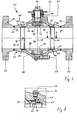
- the ball valve shown in Fig. 1 in a longitudinal section 20 has a housing 21, which consists of two to one another Approximated spherical shape complementary housing parts 22, 23rd consists.
- the two housing parts 22, 23 are by means of Screws 29 in detail not of interest here Way connected together.
- the housing parts 22, 23 have aligned flow paths 26, 27.
- At the opposite sides of the housing 21 are connected to the Housing parts 22, 23 pipe sections 71, 72 with connecting flanges 73, 74 welded, the installation of the Ball valve 20 in a pipe, not shown convey.
- a shut-off device 30 Within the housing 21 is a shut-off device 30 a Absperrkugel 31 with a through hole 32 between in the housing parts 22, 23 received seals 34, 35th arranged.
- a switching shaft 36 By means of a switching shaft 36 is the shut-off ball 31 about an axis of rotation 37 between the in Fig. 1st shown opening position 38, in which the through hole 32nd with the flow-through 26, 27 of the housing parts 22, 23rd is aligned, and one opposite the opening position 38 by 90 Degree pivoted closing position in which the flow paths 26, 27 are separated from each other, switchable and in each Intermediate position adjustable.
- the axis of rotation 37 of Switching shaft 36 is perpendicular to the through hole 32 of the shut-off ball 31.
- the Absperrkugel 31 is by means of on opposite one another Sides turned bearing journals 75, 76 in the Housing 21 recorded bearing bushes 77, 78 rotatably stored.
- the switching shaft 36 extends through a Housing attachment 79 continues and is in this in a known manner rotatably mounted and by means of a Stoffbuchsenan extract 39 against the Absperrkugel 31 receiving Housing interior sealed and not in here interesting manner rotatably with the shut-off ball 31st connected.
- the housing attachment 79 is provided with a connection plate 42 provided on which a switching drive 85th can be mounted, which in turn rotatably with the shift shaft 36 is connectable (Fig. 4).
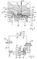
- each Seal 34, 35 has, as Figs. 2 and 3 show a preferably metallic sealing body with an on the Absperrkugel 31 pressable sealing surface 43, the spherical spherical shape of Absperrkugel 31 adapted is designed.
- the seals 34 and 35 are identical and designed Also, the seal against the housing parts 22 and 23rd is identical.
- the seal 35 is designed as a closed ring and has cylindrical support surfaces 61 on its outer periphery and 62, which are arranged parallel to each other.
- the Support surface is opposite to the support surface 62 radially to arranged outside so that the outer circumference of the Support surface 61 having wall portion of the seal 35th is greater than the outer circumference of the support surface 62nd having wall portion of the seal 35.
- the Seal 35 on its outer circumference a stepped Longitudinal cross section on.
- the seal 35 is over the Support surfaces 61 and 62 on opposite bearing surfaces 63 and 64 of the annular chamber 99 supported supported, wherein the cylindrical bearing surfaces 63 and 64 also parallel are arranged to each other.
- the seal 35 has a wall portion 51 with a Ring end face 53, which is perpendicular to the support surfaces 61 and 62 is arranged.
- the distance of this ring end face 53 of the sealing surface 43 of the seal 35 is such chosen that on at the outer surface of the shut-off ball 31 adjacent sealing surface 43 of the seal 35 an axial Switching space 48 between the annular end face 53 and the opposite annular end surface 54 of a wall portion 52nd of this seal 35 receiving housing part 23rd is trained.
- This annular switching space 48 allows limited axial displacement of the Seal 35 in the direction of the double arrow 65th
- switch room 48 opens a here perpendicular to fürströmweg 26 or perpendicular to the central longitudinal axis of the Housing part 23 arranged, cylindrical switching channel 45, wherein in the longitudinal cross section shown in FIG Inner surfaces of the switching channel 45 with the annular end faces 53 and 54 are aligned, the switch room 48 axially limit.
- the switching channel 45 is opposite to the axis of rotation 37 of Shift shaft 36 at an angle of here 90 degrees in Arranged clockwise offset.
- the switching channel 91 which is the limited axially movable Seal 34 is associated, which in turn in the annular chamber 98 of the housing part 22 is mounted, opposite the Rotary axis 37 of the switching shaft 36 at an angle from here Offset 90 degrees counterclockwise, so that both switching channels 45 and 91 are on the same side of the ball valve 20 extend.
- This arrangement of Switching channels 45 and 91 allows favorable space conditions for connection of hydraulic connection lines, the preferably to a common hydraulic channel 90 be merged (Fig. 4). Otherwise, the following conditions, the example of the switching channel 45 and the seal 35 are described in the same Way for the switching channel 91 and the seal 34th
- the switching room 48 can via the switching channel 45 with pressure (Arrow 46) are applied by preferably a in the switching channel 45 and the switching room 48 initiated hydraulic working fluid 47 with pressure (arrow 46) is charged.
- the switching channel opens 45 at its from the seal 35 facing away in a connection hole here with an internal thread for Connection of a line 45 (Fig. 4) is provided, the again switchable with pressure can be acted upon.
- the switching channel 45 and the switch chamber 48 are opposite to the Throughflow 25 with the help of designed as O-rings Ring seals 55, 56, 57, 58 sealed.
- the two ring seals 55 and 56 for sealing between the Support surface 63 and the bearing surface 61 between the Switching channel 45 and the sealing surface 43 of the seal 35th arranged and the two ring seals 57 and 58 are for Seal between the support surface 62 and the bearing surface 64 between the switching channel 45 and the of the Sealing surface 43 pointing away, frontal, annular Contact surface 67 of the seal 35 is arranged.
- the ring seals 55 and 56 are in axially spaced, parallel Ring grooves 44 of the seal 35 added, the one have trapezoidal cross-section and the outward are open.
- the ring seals 57 and 58 are also in axially spaced parallel, outwardly open Ring grooves 59 added, however, in contrast to the Ring grooves 44 in which the support surface 62 having Wall portion of the seal 35 opposite wall portion of the Housing part 32 are arranged.
- the immediately adjacent arranged to the switching channel 45 and the switch room 48 Ring seals 55 and 57 consist of one on the Working medium 47 tuned designed material while the ring seals 56 and 58 from one to the effervescent medium 28 matched designed material consist.
- the seal 35 has following the sealing surface 43rd an obliquely inward away from the Absperrkugel 31 extending work surface 66, which is opposite to the Sealing surface 43 slightly set back and in one is arranged at a shallower angle.
- This work surface 66 is directly with the medium to be blown 28 in Contact, when the flow channel 25 filled with medium or is flowed through.
- This effective projection surface 68 is in the embodiment shown the same size as an effective Projection surface 70 at the other end of the Seal 35 located contact surfaces, d. H.
- the contact surfaces 67 and 100 are also with the medium to be blown 28th directly in contact when the flow channel 25 with the is filled to be blown medium 28 or flows through it and when the seal 35 with its sealing surface 43 on the Absperrkugel 31 is present.
- the Projection surface 68 of the work surface 66 selected larger is called the projection surface 70 of the contact surfaces 67, 100. Because then one has to be smashed through Medium 28 pressure applied to the seal 35 from such pressure, that a resultant force is indicated on the seal which attempts the seal 35 from the shut-off ball 31 push away. This leads to a complete Pressure relief of the switch room 48 to the fact that the Seal 35 is lifted off the shut-off ball 31, so that then no more wear on the sealing surface 43 and on the opposite contact surfaces of Absperrkugel 31 more can occur.
- Fig. 4 is based on a circuit diagram an advantageous Embodiment of a switching arrangement important Components of the invention shown. It is 80 one Compressed air connection for connection to a not shown Compressed air pump. The compressed air generated by this can over the check valve 81 through the supply channel 87th be directed. This splits into one Working channel 88 and a working channel 93. In the Working channel 88, the compressed air via the check valve 82 are directed to a 3/2-way valve, wherein in the position shown in Fig. 4 of the 3/2-way valve 83 the Compressed air through this valve in the working channel 89th is passed, in turn, in a pressure booster 84th empties.
- this pressure booster 84 is the through the Compressed air mediated pressure in an outgoing hydraulic channel 90 reinforced, d. H. the pressure booster will open its input side fed with compressed air while on its output side the pressure via a hydraulic Medium is transmitted.
- the hydraulic channel 90 branches in two switching channels 45 and 91.
- the switching channel 45 opens into the switch room 48, which the seal 35th is assigned while the switching channel 91 in the Switching chamber 92 opens, which associated with the seal 34 is.
- the shut-off ball 31 is non-rotatable with the switching shaft 36 connected in turn rotatably with a drive element the sound drive 85 is connected, with the help of a Rotation of Absperrkugel 31 by 90 degrees from the open position in the closed position or vice versa but also in any intermediate positions is possible.
- the switching drive 85 is pneumatically controlled.
- compressed air can be supplied via the working channel 93, wherein the switching in the open position or in the Closed position achieved by means of a 5/2-way valve 86 can be.
- the compressed air via the channel 93 in a conduit 94 connected to the outlet of the valve which splits into channels 95 and 96, which allow switching of the switching drive 85.
- the compressed air is doing through the channel 97 in the Returned 5/2-way valve 86 and can be vented there become.
- the 3/2-way valve 83 switched to its second position, with the consequence of that in the compressed air chamber of the booster 84 and compressed in the working channel 89 Compressed air then be vented via the 3/2-way valve 83 can, so that the hydraulic channel 90 relieved of pressure becomes.
- the 5/2-way valve 86 switched to its second position, so that then the Compressed air via the working channel 93 in the previously as Vent channel serving channel 97 can pass to this way, a rotation-return of Absperrkugel 31 90 degrees with the help of the sound drive 85 to achieve.
- this position of the 5/2-way valve 86 is the outflowing Compressed air via the channels 95 and 96 in the channel 94th passed and can from there via the 5/2-way valve 86th be vented.
Landscapes
- Engineering & Computer Science (AREA)
- General Engineering & Computer Science (AREA)
- Mechanical Engineering (AREA)
- Taps Or Cocks (AREA)
- Fuel-Injection Apparatus (AREA)
- External Artificial Organs (AREA)
- Temperature-Responsive Valves (AREA)
- Check Valves (AREA)
- Pens And Brushes (AREA)
Applications Claiming Priority (2)
| Application Number | Priority Date | Filing Date | Title |
|---|---|---|---|
| DE10308793A DE10308793A1 (de) | 2003-02-27 | 2003-02-27 | Kugelhahn |
| DE10308793 | 2003-02-27 |
Publications (2)
| Publication Number | Publication Date |
|---|---|
| EP1452785A1 EP1452785A1 (de) | 2004-09-01 |
| EP1452785B1 true EP1452785B1 (de) | 2005-10-05 |
Family
ID=32748120
Family Applications (1)
| Application Number | Title | Priority Date | Filing Date |
|---|---|---|---|
| EP04003704A Expired - Lifetime EP1452785B1 (de) | 2003-02-27 | 2004-02-19 | Kugelhahn |
Country Status (5)
| Country | Link |
|---|---|
| US (1) | US7004451B2 (pl) |
| EP (1) | EP1452785B1 (pl) |
| AT (1) | ATE306034T1 (pl) |
| DE (2) | DE10308793A1 (pl) |
| PL (1) | PL206196B1 (pl) |
Families Citing this family (9)
| Publication number | Priority date | Publication date | Assignee | Title |
|---|---|---|---|---|
| CN102635703B (zh) * | 2012-03-29 | 2013-09-25 | 超达阀门集团股份有限公司 | 带有碟形弹簧复合体的球阀阀座结构 |
| ITMI20132031A1 (it) * | 2013-12-05 | 2015-06-06 | Ast Internat S R L | Assieme valvola |
| EP3040588B1 (en) * | 2014-12-31 | 2017-05-03 | Cameron International Corporation | Double piston effect lip seal seating assemblies |
| JP6529069B2 (ja) * | 2015-03-23 | 2019-06-12 | 株式会社Soken | バルブ装置 |
| CN106151659A (zh) * | 2015-03-31 | 2016-11-23 | 肖栋 | 一种自驱控制的活塞式阀座自密封阀门 |
| ES2779877T3 (es) * | 2016-02-18 | 2020-08-20 | Gasket Int Srl | Conjunto de sellado para válvulas de bola y válvula de bola que comprende dicho conjunto de sellado |
| EP3282156A1 (en) * | 2016-08-09 | 2018-02-14 | Cameron International Corporation | Ball valve system and method |
| CN106949259A (zh) * | 2017-05-18 | 2017-07-14 | 哈尔滨电机厂有限责任公司 | 水轮机进水球阀油压投入自退出l型金属密封 |
| CN113503375B (zh) * | 2021-07-30 | 2022-10-14 | 清华大学 | 一种压力自平衡双向密封阀座结构 |
Family Cites Families (7)
| Publication number | Priority date | Publication date | Assignee | Title |
|---|---|---|---|---|
| US3617025A (en) * | 1970-07-06 | 1971-11-02 | Grove Valve & Regulator Co | Ball valve with retractable seat rings |
| GB8800363D0 (en) * | 1988-01-08 | 1988-02-10 | Flexitallic International Valv | Ball valves |
| DE4414243B4 (de) * | 1994-04-23 | 2004-04-22 | Schmitz, Rolf, Dipl.-Ing. | Kugelhahn |
| DE19510709C2 (de) * | 1995-03-15 | 2003-12-11 | Rautenkranz Int Hermann | Absperrarmatur für Rohrleitungen mit zum Schalten druckentlastbaren Sitzringen |
| DE19701652C2 (de) | 1997-01-18 | 2001-03-08 | Argus Gmbh | Kugelhahn |
| DE19728562C2 (de) | 1997-07-04 | 2000-12-14 | Argus Gmbh | Regelbarer Kugelhahn |
| IT1321196B1 (it) * | 1999-01-26 | 2003-12-30 | Duk-Jo Jun | Dispositivo per l'apertura/chiusura di una valvola e relativo metodo |
-
2003
- 2003-02-27 DE DE10308793A patent/DE10308793A1/de not_active Withdrawn
-
2004
- 2004-02-17 PL PL365306A patent/PL206196B1/pl not_active IP Right Cessation
- 2004-02-19 EP EP04003704A patent/EP1452785B1/de not_active Expired - Lifetime
- 2004-02-19 AT AT04003704T patent/ATE306034T1/de not_active IP Right Cessation
- 2004-02-19 DE DE502004000078T patent/DE502004000078D1/de not_active Expired - Lifetime
- 2004-02-26 US US10/787,886 patent/US7004451B2/en not_active Expired - Lifetime
Also Published As
| Publication number | Publication date |
|---|---|
| US20040178380A1 (en) | 2004-09-16 |
| US7004451B2 (en) | 2006-02-28 |
| PL206196B1 (pl) | 2010-07-30 |
| PL365306A1 (pl) | 2004-09-06 |
| DE10308793A1 (de) | 2004-09-16 |
| EP1452785A1 (de) | 2004-09-01 |
| ATE306034T1 (de) | 2005-10-15 |
| DE502004000078D1 (de) | 2006-02-16 |
Similar Documents
| Publication | Publication Date | Title |
|---|---|---|
| EP3183477B1 (de) | Hydraulische steuerungsvorrichtung für ein automatikgetriebe | |
| WO2011107235A2 (de) | Mehrwegeventil | |
| DE60302382T2 (de) | Hochdruckventil | |
| EP1452785B1 (de) | Kugelhahn | |
| DE10234482B3 (de) | Vorrichtung zum Antrieb für Doppelsitzventile | |
| EP0495458A2 (de) | Rohrtrenner | |
| DE19837694B4 (de) | Coaxialventil mit Gegendruckrückentlastung | |
| DE102009012174A1 (de) | Drosselanordnung zur Verwendung in einer Fluiddruckvorrichtung | |
| DE102023117369B4 (de) | Kugelventil einer Kältemittelventileinrichtung für eine Klimaanlage | |
| EP4073407B1 (de) | Vorrichtung zum halten eines schafts eines hydraulikzylinders in stellung und verfahren zum entsperren und absperren eines sekundär-rückschlagventils der vorrichtung | |
| WO2009010077A1 (de) | Ventil für redundanzanwendungen | |
| DE4002755C2 (de) | Ventilanordnung | |
| DE20321369U1 (de) | Kugelhahn | |
| DE102004041776A1 (de) | Vorrichtung zum wahlweisen Aus- bzw. Einrücken einer Reibkupplung für Kraftfahrzeuge | |
| EP1703185B1 (de) | Coaxialventil | |
| EP1258662B1 (de) | Vorrichtung zum Absperren von von Fluiden durchströmten Rohrleitungen mittels eines kugelförmigen Verschlusskörper | |
| EP1340933B1 (de) | Hochdruckventil | |
| DE102009043568A1 (de) | Sicherheitsventil | |
| DE3620242C2 (pl) | ||
| AT379669B (de) | Absperrschieber mit im normalen betrieb unverschiebbarer spindel | |
| DE102011117086B4 (de) | UND-Ventil | |
| CH642728A5 (de) | Ventil. | |
| DE102013100004B3 (de) | Antriebseinrichtung für eine Flügeltür | |
| DE69212014T2 (de) | Manuell und pneumatisch betätigbare Absperrarmatur | |
| DE19654254C2 (de) | Mehrfach-Sitzventil |
Legal Events
| Date | Code | Title | Description |
|---|---|---|---|
| PUAI | Public reference made under article 153(3) epc to a published international application that has entered the european phase |
Free format text: ORIGINAL CODE: 0009012 |
|
| AK | Designated contracting states |
Kind code of ref document: A1 Designated state(s): AT BE BG CH CY CZ DE DK EE ES FI FR GB GR HU IE IT LI LU MC NL PT RO SE SI SK TR |
|
| AX | Request for extension of the european patent |
Extension state: AL LT LV MK |
|
| GRAP | Despatch of communication of intention to grant a patent |
Free format text: ORIGINAL CODE: EPIDOSNIGR1 |
|
| 17P | Request for examination filed |
Effective date: 20050224 |
|
| AKX | Designation fees paid |
Designated state(s): AT BE BG CH CY CZ DE DK EE ES FI FR GB GR HU IE IT LI LU MC NL PT RO SE SI SK TR |
|
| GRAS | Grant fee paid |
Free format text: ORIGINAL CODE: EPIDOSNIGR3 |
|
| GRAA | (expected) grant |
Free format text: ORIGINAL CODE: 0009210 |
|
| AK | Designated contracting states |
Kind code of ref document: B1 Designated state(s): AT BE BG CH CY CZ DE DK EE ES FI FR GB GR HU IE IT LI LU MC NL PT RO SE SI SK TR |
|
| PG25 | Lapsed in a contracting state [announced via postgrant information from national office to epo] |
Ref country code: SI Free format text: LAPSE BECAUSE OF FAILURE TO SUBMIT A TRANSLATION OF THE DESCRIPTION OR TO PAY THE FEE WITHIN THE PRESCRIBED TIME-LIMIT Effective date: 20051005 Ref country code: CZ Free format text: LAPSE BECAUSE OF FAILURE TO SUBMIT A TRANSLATION OF THE DESCRIPTION OR TO PAY THE FEE WITHIN THE PRESCRIBED TIME-LIMIT Effective date: 20051005 Ref country code: SK Free format text: LAPSE BECAUSE OF FAILURE TO SUBMIT A TRANSLATION OF THE DESCRIPTION OR TO PAY THE FEE WITHIN THE PRESCRIBED TIME-LIMIT Effective date: 20051005 Ref country code: IE Free format text: LAPSE BECAUSE OF FAILURE TO SUBMIT A TRANSLATION OF THE DESCRIPTION OR TO PAY THE FEE WITHIN THE PRESCRIBED TIME-LIMIT Effective date: 20051005 Ref country code: FI Free format text: LAPSE BECAUSE OF FAILURE TO SUBMIT A TRANSLATION OF THE DESCRIPTION OR TO PAY THE FEE WITHIN THE PRESCRIBED TIME-LIMIT Effective date: 20051005 Ref country code: RO Free format text: LAPSE BECAUSE OF FAILURE TO SUBMIT A TRANSLATION OF THE DESCRIPTION OR TO PAY THE FEE WITHIN THE PRESCRIBED TIME-LIMIT Effective date: 20051005 |
|
| REG | Reference to a national code |
Ref country code: GB Ref legal event code: FG4D Free format text: NOT ENGLISH |
|
| REG | Reference to a national code |
Ref country code: CH Ref legal event code: EP |
|
| GBT | Gb: translation of ep patent filed (gb section 77(6)(a)/1977) |
Effective date: 20051005 |
|
| REG | Reference to a national code |
Ref country code: IE Ref legal event code: FG4D Free format text: LANGUAGE OF EP DOCUMENT: GERMAN |
|
| REG | Reference to a national code |
Ref country code: CH Ref legal event code: NV Representative=s name: TROESCH SCHEIDEGGER WERNER AG |
|
| PG25 | Lapsed in a contracting state [announced via postgrant information from national office to epo] |
Ref country code: GR Free format text: LAPSE BECAUSE OF FAILURE TO SUBMIT A TRANSLATION OF THE DESCRIPTION OR TO PAY THE FEE WITHIN THE PRESCRIBED TIME-LIMIT Effective date: 20060105 Ref country code: DK Free format text: LAPSE BECAUSE OF FAILURE TO SUBMIT A TRANSLATION OF THE DESCRIPTION OR TO PAY THE FEE WITHIN THE PRESCRIBED TIME-LIMIT Effective date: 20060105 Ref country code: SE Free format text: LAPSE BECAUSE OF FAILURE TO SUBMIT A TRANSLATION OF THE DESCRIPTION OR TO PAY THE FEE WITHIN THE PRESCRIBED TIME-LIMIT Effective date: 20060105 Ref country code: BG Free format text: LAPSE BECAUSE OF FAILURE TO SUBMIT A TRANSLATION OF THE DESCRIPTION OR TO PAY THE FEE WITHIN THE PRESCRIBED TIME-LIMIT Effective date: 20060105 |
|
| PG25 | Lapsed in a contracting state [announced via postgrant information from national office to epo] |
Ref country code: ES Free format text: LAPSE BECAUSE OF FAILURE TO SUBMIT A TRANSLATION OF THE DESCRIPTION OR TO PAY THE FEE WITHIN THE PRESCRIBED TIME-LIMIT Effective date: 20060116 |
|
| REF | Corresponds to: |
Ref document number: 502004000078 Country of ref document: DE Date of ref document: 20060216 Kind code of ref document: P |
|
| PG25 | Lapsed in a contracting state [announced via postgrant information from national office to epo] |
Ref country code: MC Free format text: LAPSE BECAUSE OF NON-PAYMENT OF DUE FEES Effective date: 20060228 Ref country code: BE Free format text: LAPSE BECAUSE OF NON-PAYMENT OF DUE FEES Effective date: 20060228 Ref country code: LU Free format text: LAPSE BECAUSE OF NON-PAYMENT OF DUE FEES Effective date: 20060228 |
|
| PG25 | Lapsed in a contracting state [announced via postgrant information from national office to epo] |
Ref country code: PT Free format text: LAPSE BECAUSE OF FAILURE TO SUBMIT A TRANSLATION OF THE DESCRIPTION OR TO PAY THE FEE WITHIN THE PRESCRIBED TIME-LIMIT Effective date: 20060306 |
|
| PG25 | Lapsed in a contracting state [announced via postgrant information from national office to epo] |
Ref country code: HU Free format text: LAPSE BECAUSE OF FAILURE TO SUBMIT A TRANSLATION OF THE DESCRIPTION OR TO PAY THE FEE WITHIN THE PRESCRIBED TIME-LIMIT Effective date: 20060406 |
|
| REG | Reference to a national code |
Ref country code: IE Ref legal event code: FD4D |
|
| ET | Fr: translation filed | ||
| PLBE | No opposition filed within time limit |
Free format text: ORIGINAL CODE: 0009261 |
|
| STAA | Information on the status of an ep patent application or granted ep patent |
Free format text: STATUS: NO OPPOSITION FILED WITHIN TIME LIMIT |
|
| 26N | No opposition filed |
Effective date: 20060706 |
|
| BERE | Be: lapsed |
Owner name: FLOWSERVE FLOW CONTROL G.M.B.H. Effective date: 20060228 |
|
| PG25 | Lapsed in a contracting state [announced via postgrant information from national office to epo] |
Ref country code: EE Free format text: LAPSE BECAUSE OF FAILURE TO SUBMIT A TRANSLATION OF THE DESCRIPTION OR TO PAY THE FEE WITHIN THE PRESCRIBED TIME-LIMIT Effective date: 20051005 |
|
| PG25 | Lapsed in a contracting state [announced via postgrant information from national office to epo] |
Ref country code: TR Free format text: LAPSE BECAUSE OF FAILURE TO SUBMIT A TRANSLATION OF THE DESCRIPTION OR TO PAY THE FEE WITHIN THE PRESCRIBED TIME-LIMIT Effective date: 20051005 |
|
| PG25 | Lapsed in a contracting state [announced via postgrant information from national office to epo] |
Ref country code: CY Free format text: LAPSE BECAUSE OF FAILURE TO SUBMIT A TRANSLATION OF THE DESCRIPTION OR TO PAY THE FEE WITHIN THE PRESCRIBED TIME-LIMIT Effective date: 20051005 |
|
| PGFP | Annual fee paid to national office [announced via postgrant information from national office to epo] |
Ref country code: FR Payment date: 20100311 Year of fee payment: 7 Ref country code: IT Payment date: 20100225 Year of fee payment: 7 |
|
| PGFP | Annual fee paid to national office [announced via postgrant information from national office to epo] |
Ref country code: AT Payment date: 20100202 Year of fee payment: 7 Ref country code: GB Payment date: 20100210 Year of fee payment: 7 |
|
| PGFP | Annual fee paid to national office [announced via postgrant information from national office to epo] |
Ref country code: NL Payment date: 20100215 Year of fee payment: 7 |
|
| PGFP | Annual fee paid to national office [announced via postgrant information from national office to epo] |
Ref country code: CH Payment date: 20100427 Year of fee payment: 7 |
|
| REG | Reference to a national code |
Ref country code: NL Ref legal event code: V1 Effective date: 20110901 |
|
| REG | Reference to a national code |
Ref country code: CH Ref legal event code: PL |
|
| GBPC | Gb: european patent ceased through non-payment of renewal fee |
Effective date: 20110219 |
|
| PG25 | Lapsed in a contracting state [announced via postgrant information from national office to epo] |
Ref country code: CH Free format text: LAPSE BECAUSE OF NON-PAYMENT OF DUE FEES Effective date: 20110228 Ref country code: LI Free format text: LAPSE BECAUSE OF NON-PAYMENT OF DUE FEES Effective date: 20110228 |
|
| REG | Reference to a national code |
Ref country code: FR Ref legal event code: ST Effective date: 20111102 |
|
| PG25 | Lapsed in a contracting state [announced via postgrant information from national office to epo] |
Ref country code: AT Free format text: LAPSE BECAUSE OF NON-PAYMENT OF DUE FEES Effective date: 20110219 |
|
| PG25 | Lapsed in a contracting state [announced via postgrant information from national office to epo] |
Ref country code: NL Free format text: LAPSE BECAUSE OF NON-PAYMENT OF DUE FEES Effective date: 20110901 Ref country code: IT Free format text: LAPSE BECAUSE OF NON-PAYMENT OF DUE FEES Effective date: 20110219 |
|
| PG25 | Lapsed in a contracting state [announced via postgrant information from national office to epo] |
Ref country code: FR Free format text: LAPSE BECAUSE OF NON-PAYMENT OF DUE FEES Effective date: 20110228 |
|
| PG25 | Lapsed in a contracting state [announced via postgrant information from national office to epo] |
Ref country code: GB Free format text: LAPSE BECAUSE OF NON-PAYMENT OF DUE FEES Effective date: 20110219 |
|
| PGFP | Annual fee paid to national office [announced via postgrant information from national office to epo] |
Ref country code: DE Payment date: 20160218 Year of fee payment: 13 |
|
| REG | Reference to a national code |
Ref country code: DE Ref legal event code: R119 Ref document number: 502004000078 Country of ref document: DE |
|
| PG25 | Lapsed in a contracting state [announced via postgrant information from national office to epo] |
Ref country code: DE Free format text: LAPSE BECAUSE OF NON-PAYMENT OF DUE FEES Effective date: 20170901 |