EP1452734A2 - Hybrid compressor system - Google Patents
Hybrid compressor system Download PDFInfo
- Publication number
- EP1452734A2 EP1452734A2 EP04004384A EP04004384A EP1452734A2 EP 1452734 A2 EP1452734 A2 EP 1452734A2 EP 04004384 A EP04004384 A EP 04004384A EP 04004384 A EP04004384 A EP 04004384A EP 1452734 A2 EP1452734 A2 EP 1452734A2
- Authority
- EP
- European Patent Office
- Prior art keywords
- driving force
- compressor
- motor
- way clutch
- outer ring
- Prior art date
- Legal status (The legal status is an assumption and is not a legal conclusion. Google has not performed a legal analysis and makes no representation as to the accuracy of the status listed.)
- Withdrawn
Links
Images

Classifications
-
- F—MECHANICAL ENGINEERING; LIGHTING; HEATING; WEAPONS; BLASTING
- F04—POSITIVE - DISPLACEMENT MACHINES FOR LIQUIDS; PUMPS FOR LIQUIDS OR ELASTIC FLUIDS
- F04B—POSITIVE-DISPLACEMENT MACHINES FOR LIQUIDS; PUMPS
- F04B27/00—Multi-cylinder pumps specially adapted for elastic fluids and characterised by number or arrangement of cylinders
- F04B27/08—Multi-cylinder pumps specially adapted for elastic fluids and characterised by number or arrangement of cylinders having cylinders coaxial with, or parallel or inclined to, main shaft axis
- F04B27/0873—Component parts, e.g. sealings; Manufacturing or assembly thereof
- F04B27/0895—Component parts, e.g. sealings; Manufacturing or assembly thereof driving means
-
- B—PERFORMING OPERATIONS; TRANSPORTING
- B60—VEHICLES IN GENERAL
- B60H—ARRANGEMENTS OF HEATING, COOLING, VENTILATING OR OTHER AIR-TREATING DEVICES SPECIALLY ADAPTED FOR PASSENGER OR GOODS SPACES OF VEHICLES
- B60H1/00—Heating, cooling or ventilating devices
- B60H1/32—Cooling devices
- B60H1/3204—Cooling devices using compression
- B60H1/3222—Cooling devices using compression characterised by the compressor driving arrangements, e.g. clutches, transmissions or multiple drives
-
- F—MECHANICAL ENGINEERING; LIGHTING; HEATING; WEAPONS; BLASTING
- F04—POSITIVE - DISPLACEMENT MACHINES FOR LIQUIDS; PUMPS FOR LIQUIDS OR ELASTIC FLUIDS
- F04C—ROTARY-PISTON, OR OSCILLATING-PISTON, POSITIVE-DISPLACEMENT MACHINES FOR LIQUIDS; ROTARY-PISTON, OR OSCILLATING-PISTON, POSITIVE-DISPLACEMENT PUMPS
- F04C2240/00—Components
- F04C2240/45—Hybrid prime mover
Definitions
- the present invention relates to a hybrid compressor system mounted in a vehicle which stops a vehicle-driving power source during idling for selectively transmitting a driving force of the vehicle-driving power source and a driving force of a motor mounted on the vehicle to a compressor of a vehicle air conditioning device, thereby driving the compressor.
- a related hybrid compressor system it is proposed to transmit a driving force of an engine to a compressor by engaging or disengaging an electromagnetic clutch, and to transmit a driving force of a motor to the compressor by engaging or disengaging a one-way clutch.
- the one-way clutch is brought into a transmitting(connecting) state when the motor is driven, and is brought into an idling (disconnecting) state when the engine is driven.
- the one-way clutch is provided on an inner peripheral side of a pulley to which the driving force of the engine is transmitted and is disposed between bearings.
- the one-way clutch is disposed in a small space, a diameter of the one-way clutch is set small. Thus, there is a problem that when the compressor rotates at a high speed, seizure is prone to be generated.
- the present invention has been accomplished in view of the above problems, and the present invention provides a hybrid compressor system in which a configuration of the system is simplified, a size thereof is reduced, and a reliability of the system is enhanced.
- the system comprises a one-way clutch which selectively transmits the driving force of the auxiliary power source, and the one-way clutch is mounted on the motor.
- Fig. 1 is a partially cut-away side view of a hybrid compressor system according to an embodiment of the present invention
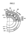
- Fig. 2 is a sectional view taken along the line II-II in Fig. 1.
- the hybrid compressor system is used in an idling stop vehicle.
- a compressor 1 is selectively driven by two driving sources, i.e., an engine E as a vehicle-driving power source and a motor M as an auxiliary power source mounted in the vehicle.
- the compressor 1 is of a variable-capacitance type and includes a compression mechanism which compresses a refrigerant by rotation of a rotation shaft 3.
- a housing 2 includes a cylinder block 2a having a plurality of cylinder bores 4, a front housing 2b which is connected to a front end surface of the cylinder block 2a to form a crank case 5 between the cylinder block 2a and the front housing 2b, and a rear housing 2c connected to a rear end surface of the cylinder block 2a through a valve plate 6.
- a suction chamber 7 and a discharge chamber 8 are formed in the rear housing 2c by a division wall.
- the suction chamber 7 is in communication with the cylinder bore 4 through a suction hole 9 having a valve mechanism
- the discharge chamber 8 is in communication with the cylinder bore 4 through a discharge hole 10 having a valve mechanism.
- the rotation shaft 3 is rotatably supported by an inner peripheral surface of a through hole 11 formed in a central portion of the cylinder block 2 and by an inner peripheral surface of a cylindrical support section 12 formed on a front end of the front housing 2b through bearings 13 and 14. A front end of the rotation shaft 3 projects from the support section 12 outside the housing 2.
- the compression mechanism is disposed in the crank case 5.
- the compression mechanism includes a rocking plate 15 which is non-rotatably and rockably mounted on the rotation shaft 3, and a piston 17 which is connected to the rocking plate 15 through a piston rod 16 and which reciprocates in the cylinder bore 4 by the rocking motion of the rocking plate 15. Therefore, if the rotation shaft 3 rotates, the piston 17 reciprocates in the cylinder bore 4 and with this motion, a refrigerant drawn into the cylinder bore 4 from the suction chamber 7 through the suction hole 9 is compressed, and is discharged into the discharge chamber 8 through the discharge hole 10.
- the rear housing 2c is provided with pressure control means 24 which is in communication with the crank case 5, the suction chamber 7, and the discharge chamber 8, and which controls pressure in these crank case 5, suction chamber 7, and discharge chamber 8.
- the inclination angle of the rocking plate 15 is adjusted by the pressure control means 24 and the discharge amount of the refrigerant is adjusted.
- An electromagnetic clutch 100 includes a rotor 110, an armature 120, and a coil section 130.
- the rotor 110 is formed into an annular shape, and is rotatably supported by an outer peripheral surface of the support section 12 of the front housing 2b of the compressor 1 through a bearing 111.
- a cross section of the rotor 110 is formed into a C-shape such that the rotor 110 opens rearward, and a V-shaped groove 112 is formed in the outer peripheral surface of the rotor 110.
- a V-belt EV is wound around the groove 112 and an outer peripheral surface of a drive pulley EP mounted on an output shaft of the engine E .
- the armature 120 includes a substantially disk-like hub 121 fitted into a tip end of the rotation shaft 3, a flexible member 122 fixed to the hub 121, and a metal clutch plate 123 mounted on the flexible member 122 such as to be opposed to a front end surface of the rotor 110.
- the coil section 130 has a coil 132 made of resin.
- the coil 132 is formed by molding in a stator 131 accommodated in the rotor 110.
- the coil section 130 is energized and dienergized upon reception of a signal from a clutch control circuit (not shown). If the coil section 130 is energized, a front end surface of the rotor 110 and the clutch plate 123 of the armature 120 are connected to each other, and the rotation shaft 3 is rotated by a driving force from the engine E .
- a pulley 200 is fixed to a front end surface of the hub 121.
- a belt MV is wound around an outer peripheral surface of the pulley 200 and an outer peripheral surface of an outer ring 330 of the one-way clutch 300 mounted on an output shaft of the motor M .
- the one-way clutch 300 comprises an inner ring 310 concentrically fixed to the output shaft of the motor through an annular mounting member 25, an outer ring 330 concentrically and rotatably disposed on an outer side of the inner ring 310 through a bearing 320, and interrupting means 340 (see Fig. 2) which brings the inner ring 310 and the outer ring 330 into connection with each other such that a force is transmitted therebetween, and which releases the connection by centrifugal force.
- a V-shaped groove 350 is formed in the outer peripheral surface of the outer ring 330.
- the belt MV is wound around the groove 350 and the outer peripheral surface of the pulley 200. That is, the outer ring 330 also functions as a pulley, and this simplifies the configuration and reduces the size of the system.
- the interrupting means 340 is provided in an annular gap G formed between the inner ring 310 and the outer ring 330. That is, the interrupting means 340 includes a plurality of rollers 360. The rollers 360 are arranged in the gap G at constant distances from one another in the circumferential direction and can move in the circumferential direction.
- the interrupting means 340 also includes spring seats 370 which are adjacent to the rollers 360 in the rotational direction (direction of an arrow R ) and which are fixed to the outer ring 330.
- the interrupting means 340 also includes springs 380 respectively mounted on the spring seats 370 for biasing the roller 360 in a direction opposite from the rotational direction.
- Notches 390 on which the rollers 360 slide are provided in an inner periphery of the outer ring 330.
- Each of the notches 390 is formed such that its depth increases toward the rotational direction R .
- the rollers 360 are pushed against the notches 390 and the outer peripheral surface of the inner ring 310 by the springs 370. If the motor M is driven, the outer ring 330 rotates in unison with the inner ring 310 by wedge effect between the notches 390 and the inner ring 310.
- each roller 360 pushes and compresses the spring 370 by a centrifugal force corresponding to the angular rotational speed and the rollers 360 enter the deep portions of the notches 390, and the rollers 360 are separated from the outer peripheral surface of the inner ring 310.
- the connection between the inner ring 310 and the outer ring 330 is released and thus, the outer ring 330 idles with respect to the inner ring 310, and the transmission of the driving force from the motor M to the pulley 200 of the compressor 1 is cut off.
- the hybrid compressor system is controlled by an ECU having a clutch control circuit, a motor control circuit, a discharge capacity control circuit and the like.
- the control operation will be explained based on running states of an idling stop vehicle.
- the motor M is provided with the one-way clutch 300, and the rotor 110 to which the driving force from the engine E is transmitted can be reduced in size in both radial direction and axial direction of the rotation shaft 3.
- the pulley 200 having the simple configuration can function as the transmitting mechanism of the driving force from the motor M added to the compressor 1, the transmitting mechanism of the driving force added to the compressor 1 is reduced in size and its configuration is simplified, and the cost is reduced.
- the motor M with the one-way clutch 300, it is possible to use the one-way clutch 300 whose large-diameter outer ring idle, in which seizure is less prone to be generated even at a high speed rotation, thus enhancing the reliability.
- the one-way clutch 300 is of centrifugal force type, there is a merit that its configuration is simple and its size is small as compared with a one-way clutch of another type.
- the outer ring 330 of the one-way clutch 300 also functions as the pulley, the configuration is further simplified, and the cost and the size are further reduced.
- the present invention can also be applied to a hybrid compressor system using a vehicle-driving power source other than engine.
Landscapes
- Engineering & Computer Science (AREA)
- Mechanical Engineering (AREA)
- Manufacturing & Machinery (AREA)
- General Engineering & Computer Science (AREA)
- Physics & Mathematics (AREA)
- Thermal Sciences (AREA)
- Compressors, Vaccum Pumps And Other Relevant Systems (AREA)
- Air-Conditioning For Vehicles (AREA)
Abstract
Description
Claims (3)
- A hybrid compressor system for selectively transmitting a driving force of a vehicle-driving power source (E) and a driving force of an auxiliary power source (M) to a compressor (1) of a vehicle air conditioning device, comprising:an one-way clutch (300) selectively transmitting the driving force of the auxiliary power source to the compressor, the one-way clutch being mounted on the auxiliary power source.
- The hybrid compressor system according to claim 1, wherein
the one-way clutch (300) includes:an inner ring (310) fixed to an output shaft of the motor (M):an outer ring (330) being concentrically and rotatably disposed on an outer side of the inner ring (310) ; andinterrupting means (340) connecting the inner ring (310) and the outer ring (330) such that the force is transmitted therebetween, and releasing the connection therebetween by a predetermined centrifugal force corresponding to the rotation of the outer ring. - The hybrid compressor system according to claim 2, wherein
the outer ring is a pulley; and
a belt (MV) for transmitting the driving force to the compressor is wound around the pulley.
Applications Claiming Priority (2)
| Application Number | Priority Date | Filing Date | Title |
|---|---|---|---|
| JP2003050689A JP2004256045A (en) | 2003-02-27 | 2003-02-27 | Hybrid compressor system |
| JP2003050689 | 2003-02-27 |
Publications (2)
| Publication Number | Publication Date |
|---|---|
| EP1452734A2 true EP1452734A2 (en) | 2004-09-01 |
| EP1452734A3 EP1452734A3 (en) | 2006-01-25 |
Family
ID=32767790
Family Applications (1)
| Application Number | Title | Priority Date | Filing Date |
|---|---|---|---|
| EP04004384A Withdrawn EP1452734A3 (en) | 2003-02-27 | 2004-02-26 | Hybrid compressor system |
Country Status (3)
| Country | Link |
|---|---|
| US (1) | US7104765B2 (en) |
| EP (1) | EP1452734A3 (en) |
| JP (1) | JP2004256045A (en) |
Families Citing this family (10)
| Publication number | Priority date | Publication date | Assignee | Title |
|---|---|---|---|---|
| US20080314059A1 (en) * | 2007-06-20 | 2008-12-25 | Thermo King Corporation | Double clutch drive system |
| US20090000836A1 (en) * | 2007-06-30 | 2009-01-01 | Paul Harriman Kydd | Balanced Belt or Chain Drive for Electric Hybrid Vehicle Conversion |
| US20100158702A1 (en) * | 2008-12-18 | 2010-06-24 | Bendix Commercial Vehicle Systems | Air compressor system |
| IT1393277B1 (en) * | 2009-03-17 | 2012-04-12 | Vhit Spa | ROTARY VACUUM PUMP WITH A DISMANTLING DEVICE FROM THE DRIVE MOTOR |
| US8491274B2 (en) * | 2009-09-21 | 2013-07-23 | Richard D Taylor | System for operating an air conditioning compressor from alternative sources |
| WO2012138500A1 (en) | 2011-04-04 | 2012-10-11 | Carrier Corporation | Transport refrigeration system and method for operating |
| US20150267948A1 (en) * | 2014-03-24 | 2015-09-24 | Richard D. Taylor | System and method for operating an air conditioning compressor from alternative sources |
| KR101588746B1 (en) * | 2014-09-05 | 2016-01-26 | 현대자동차 주식회사 | Hybrid compressor |
| US11577581B2 (en) | 2016-06-24 | 2023-02-14 | Cummins Inc. | Apparatus and system for controlling power to an air conditioning compressor for a vehicle |
| DE102020006374A1 (en) * | 2020-10-16 | 2021-04-15 | Daimler Ag | Air conditioning device for a motor vehicle and motor vehicle with such an air conditioning device |
Family Cites Families (16)
| Publication number | Priority date | Publication date | Assignee | Title |
|---|---|---|---|---|
| US107635A (en) * | 1870-09-20 | Improvement in rotary air-wheels for gas-carbureters | ||
| US5543802A (en) * | 1993-03-01 | 1996-08-06 | Motorola, Inc. | Position/navigation device and method |
| JPH07260507A (en) * | 1994-03-16 | 1995-10-13 | Mitsumi Electric Co Ltd | GPS receiver |
| US6321158B1 (en) * | 1994-06-24 | 2001-11-20 | Delorme Publishing Company | Integrated routing/mapping information |
| US6459987B1 (en) * | 1996-11-15 | 2002-10-01 | Garmin Corporation | Method and apparatus for backtracking a path |
| JP3555404B2 (en) | 1997-02-24 | 2004-08-18 | 株式会社デンソー | Control device of hybrid compressor for vehicle |
| US5867996A (en) * | 1997-02-24 | 1999-02-09 | Denso Corporation | Compressor control device for vehicle air conditioner |
| US6234769B1 (en) * | 1997-07-09 | 2001-05-22 | Denso Corporation | Hybrid type compressor driven by engine and electric motor |
| US6115655A (en) * | 1998-01-27 | 2000-09-05 | Keith; W. Curtis | Method for monitoring and reporting vehicular mileage |
| US6199010B1 (en) * | 1998-05-04 | 2001-03-06 | Lucent Technologies, Inc. | Wireless telecommunications system that provides navigational assistance to travelers |
| JP4067701B2 (en) * | 1999-06-10 | 2008-03-26 | カルソニックカンセイ株式会社 | Air conditioner for vehicles |
| JP3391750B2 (en) * | 1999-10-28 | 2003-03-31 | 株式会社デンソー | Vehicle accessory drive |
| US6354821B1 (en) * | 2000-11-22 | 2002-03-12 | Scroll Technologies | Scroll compressor with dual clutch capacity modulation |
| JP2002364535A (en) * | 2001-06-08 | 2002-12-18 | Toyota Industries Corp | Rotating device |
| JP2003166467A (en) * | 2001-11-29 | 2003-06-13 | Toyota Industries Corp | Rotating machine for vehicle |
| US6638027B2 (en) * | 2001-12-11 | 2003-10-28 | Visteon Global Technologies, Inc. | Hybrid compressor with bearing clutch assembly |
-
2003
- 2003-02-27 JP JP2003050689A patent/JP2004256045A/en not_active Withdrawn
-
2004
- 2004-02-26 EP EP04004384A patent/EP1452734A3/en not_active Withdrawn
- 2004-02-27 US US10/789,925 patent/US7104765B2/en not_active Expired - Fee Related
Also Published As
| Publication number | Publication date |
|---|---|
| US7104765B2 (en) | 2006-09-12 |
| US20040237556A1 (en) | 2004-12-02 |
| JP2004256045A (en) | 2004-09-16 |
| EP1452734A3 (en) | 2006-01-25 |
Similar Documents
| Publication | Publication Date | Title |
|---|---|---|
| US8371426B2 (en) | Power transmission mechanism | |
| US7104765B2 (en) | Hybrid compressor system | |
| JP3708499B2 (en) | Combined auxiliary machine control device for vehicle | |
| US6617727B2 (en) | Vehicular rotational apparatus | |
| JP4273800B2 (en) | Compressor with torque limiter | |
| JP3956460B2 (en) | Combined compression device | |
| US6821094B2 (en) | Hybrid power transmission system having first and second clutch mechanisms | |
| US6019693A (en) | Method for mounting two auxiliary machines to automobile and power transmission device | |
| JP4045633B2 (en) | Auxiliary drive system using starter motor | |
| US20120251347A1 (en) | Compressor with transmission | |
| EP0093045A1 (en) | Double acting drive mechanism | |
| US6213882B1 (en) | Power transmission mechanism and its assembly method | |
| EP1452777B1 (en) | Power transmission device | |
| JP2002242829A (en) | Variable displacement compressor | |
| EP1253319A2 (en) | Drive mechanism for swash plate compressor | |
| JP2004301008A (en) | Double pulley compressor and hybrid compressor system | |
| US7320576B2 (en) | Clutchless variable displacement refrigerant compressor with mechanism for reducing displacement work at increased driven speed during non-operation of refrigerating system including the compressor | |
| US20050124446A1 (en) | Positioning structure for power transmission mechanism | |
| JP2004299521A (en) | Hybrid compressor system | |
| JP2008057681A (en) | Belt transmission device | |
| JP2002081375A (en) | Hybrid compressor | |
| JP2000265948A (en) | Variable capacity compressor | |
| JP4553083B2 (en) | Vibration isolator for compressor for passenger compartment air conditioner | |
| JP2003139160A (en) | Motive power transmission device | |
| KR20240050689A (en) | Compressor and method for manufacturing pulley included therein |
Legal Events
| Date | Code | Title | Description |
|---|---|---|---|
| PUAI | Public reference made under article 153(3) epc to a published international application that has entered the european phase |
Free format text: ORIGINAL CODE: 0009012 |
|
| AK | Designated contracting states |
Kind code of ref document: A2 Designated state(s): AT BE BG CH CY CZ DE DK EE ES FI FR GB GR HU IE IT LI LU MC NL PT RO SE SI SK TR |
|
| AX | Request for extension of the european patent |
Extension state: AL LT LV MK |
|
| PUAL | Search report despatched |
Free format text: ORIGINAL CODE: 0009013 |
|
| AK | Designated contracting states |
Kind code of ref document: A3 Designated state(s): AT BE BG CH CY CZ DE DK EE ES FI FR GB GR HU IE IT LI LU MC NL PT RO SE SI SK TR |
|
| AX | Request for extension of the european patent |
Extension state: AL LT LV MK |
|
| 17P | Request for examination filed |
Effective date: 20060215 |
|
| AKX | Designation fees paid |
Designated state(s): DE FR GB |
|
| 17Q | First examination report despatched |
Effective date: 20090806 |
|
| STAA | Information on the status of an ep patent application or granted ep patent |
Free format text: STATUS: THE APPLICATION IS DEEMED TO BE WITHDRAWN |
|
| 18D | Application deemed to be withdrawn |
Effective date: 20091217 |