EP1452717A1 - Fuel injection valve - Google Patents
Fuel injection valve Download PDFInfo
- Publication number
- EP1452717A1 EP1452717A1 EP01274709A EP01274709A EP1452717A1 EP 1452717 A1 EP1452717 A1 EP 1452717A1 EP 01274709 A EP01274709 A EP 01274709A EP 01274709 A EP01274709 A EP 01274709A EP 1452717 A1 EP1452717 A1 EP 1452717A1
- Authority
- EP
- European Patent Office
- Prior art keywords
- valve
- guide
- fuel injection
- movable element
- injection valve
- Prior art date
- Legal status (The legal status is an assumption and is not a legal conclusion. Google has not performed a legal analysis and makes no representation as to the accuracy of the status listed.)
- Granted
Links
Images





Classifications
-
- F—MECHANICAL ENGINEERING; LIGHTING; HEATING; WEAPONS; BLASTING
- F02—COMBUSTION ENGINES; HOT-GAS OR COMBUSTION-PRODUCT ENGINE PLANTS
- F02M—SUPPLYING COMBUSTION ENGINES IN GENERAL WITH COMBUSTIBLE MIXTURES OR CONSTITUENTS THEREOF
- F02M21/00—Apparatus for supplying engines with non-liquid fuels, e.g. gaseous fuels stored in liquid form
- F02M21/02—Apparatus for supplying engines with non-liquid fuels, e.g. gaseous fuels stored in liquid form for gaseous fuels
- F02M21/0218—Details on the gaseous fuel supply system, e.g. tanks, valves, pipes, pumps, rails, injectors or mixers
- F02M21/0248—Injectors
- F02M21/0257—Details of the valve closing elements, e.g. valve seats, stems or arrangement of flow passages
- F02M21/026—Lift valves, i.e. stem operated valves
- F02M21/0263—Inwardly opening single or multi nozzle valves, e.g. needle valves
- F02M21/0266—Hollow stem valves; Piston valves; Stems having a spherical tip
-
- F—MECHANICAL ENGINEERING; LIGHTING; HEATING; WEAPONS; BLASTING
- F02—COMBUSTION ENGINES; HOT-GAS OR COMBUSTION-PRODUCT ENGINE PLANTS
- F02M—SUPPLYING COMBUSTION ENGINES IN GENERAL WITH COMBUSTIBLE MIXTURES OR CONSTITUENTS THEREOF
- F02M21/00—Apparatus for supplying engines with non-liquid fuels, e.g. gaseous fuels stored in liquid form
- F02M21/02—Apparatus for supplying engines with non-liquid fuels, e.g. gaseous fuels stored in liquid form for gaseous fuels
- F02M21/0218—Details on the gaseous fuel supply system, e.g. tanks, valves, pipes, pumps, rails, injectors or mixers
- F02M21/0248—Injectors
- F02M21/0251—Details of actuators therefor
- F02M21/0254—Electric actuators, e.g. solenoid or piezoelectric
-
- F—MECHANICAL ENGINEERING; LIGHTING; HEATING; WEAPONS; BLASTING
- F02—COMBUSTION ENGINES; HOT-GAS OR COMBUSTION-PRODUCT ENGINE PLANTS
- F02M—SUPPLYING COMBUSTION ENGINES IN GENERAL WITH COMBUSTIBLE MIXTURES OR CONSTITUENTS THEREOF
- F02M21/00—Apparatus for supplying engines with non-liquid fuels, e.g. gaseous fuels stored in liquid form
- F02M21/02—Apparatus for supplying engines with non-liquid fuels, e.g. gaseous fuels stored in liquid form for gaseous fuels
- F02M21/0218—Details on the gaseous fuel supply system, e.g. tanks, valves, pipes, pumps, rails, injectors or mixers
- F02M21/0296—Manufacturing or assembly; Materials, e.g. coatings
-
- F—MECHANICAL ENGINEERING; LIGHTING; HEATING; WEAPONS; BLASTING
- F02—COMBUSTION ENGINES; HOT-GAS OR COMBUSTION-PRODUCT ENGINE PLANTS
- F02M—SUPPLYING COMBUSTION ENGINES IN GENERAL WITH COMBUSTIBLE MIXTURES OR CONSTITUENTS THEREOF
- F02M51/00—Fuel-injection apparatus characterised by being operated electrically
- F02M51/06—Injectors peculiar thereto with means directly operating the valve needle
- F02M51/061—Injectors peculiar thereto with means directly operating the valve needle using electromagnetic operating means
- F02M51/0625—Injectors peculiar thereto with means directly operating the valve needle using electromagnetic operating means characterised by arrangement of mobile armatures
- F02M51/0664—Injectors peculiar thereto with means directly operating the valve needle using electromagnetic operating means characterised by arrangement of mobile armatures having a cylindrically or partly cylindrically shaped armature, e.g. entering the winding; having a plate-shaped or undulated armature entering the winding
- F02M51/0667—Injectors peculiar thereto with means directly operating the valve needle using electromagnetic operating means characterised by arrangement of mobile armatures having a cylindrically or partly cylindrically shaped armature, e.g. entering the winding; having a plate-shaped or undulated armature entering the winding the armature acting as a valve or having a short valve body attached thereto
-
- F—MECHANICAL ENGINEERING; LIGHTING; HEATING; WEAPONS; BLASTING
- F02—COMBUSTION ENGINES; HOT-GAS OR COMBUSTION-PRODUCT ENGINE PLANTS
- F02M—SUPPLYING COMBUSTION ENGINES IN GENERAL WITH COMBUSTIBLE MIXTURES OR CONSTITUENTS THEREOF
- F02M51/00—Fuel-injection apparatus characterised by being operated electrically
- F02M51/06—Injectors peculiar thereto with means directly operating the valve needle
- F02M51/061—Injectors peculiar thereto with means directly operating the valve needle using electromagnetic operating means
- F02M51/0625—Injectors peculiar thereto with means directly operating the valve needle using electromagnetic operating means characterised by arrangement of mobile armatures
- F02M51/0664—Injectors peculiar thereto with means directly operating the valve needle using electromagnetic operating means characterised by arrangement of mobile armatures having a cylindrically or partly cylindrically shaped armature, e.g. entering the winding; having a plate-shaped or undulated armature entering the winding
- F02M51/0671—Injectors peculiar thereto with means directly operating the valve needle using electromagnetic operating means characterised by arrangement of mobile armatures having a cylindrically or partly cylindrically shaped armature, e.g. entering the winding; having a plate-shaped or undulated armature entering the winding the armature having an elongated valve body attached thereto
-
- F—MECHANICAL ENGINEERING; LIGHTING; HEATING; WEAPONS; BLASTING
- F02—COMBUSTION ENGINES; HOT-GAS OR COMBUSTION-PRODUCT ENGINE PLANTS
- F02M—SUPPLYING COMBUSTION ENGINES IN GENERAL WITH COMBUSTIBLE MIXTURES OR CONSTITUENTS THEREOF
- F02M51/00—Fuel-injection apparatus characterised by being operated electrically
- F02M51/06—Injectors peculiar thereto with means directly operating the valve needle
- F02M51/061—Injectors peculiar thereto with means directly operating the valve needle using electromagnetic operating means
- F02M51/0625—Injectors peculiar thereto with means directly operating the valve needle using electromagnetic operating means characterised by arrangement of mobile armatures
- F02M51/0664—Injectors peculiar thereto with means directly operating the valve needle using electromagnetic operating means characterised by arrangement of mobile armatures having a cylindrically or partly cylindrically shaped armature, e.g. entering the winding; having a plate-shaped or undulated armature entering the winding
- F02M51/0671—Injectors peculiar thereto with means directly operating the valve needle using electromagnetic operating means characterised by arrangement of mobile armatures having a cylindrically or partly cylindrically shaped armature, e.g. entering the winding; having a plate-shaped or undulated armature entering the winding the armature having an elongated valve body attached thereto
- F02M51/0675—Injectors peculiar thereto with means directly operating the valve needle using electromagnetic operating means characterised by arrangement of mobile armatures having a cylindrically or partly cylindrically shaped armature, e.g. entering the winding; having a plate-shaped or undulated armature entering the winding the armature having an elongated valve body attached thereto the valve body having cylindrical guiding or metering portions, e.g. with fuel passages
-
- F—MECHANICAL ENGINEERING; LIGHTING; HEATING; WEAPONS; BLASTING
- F02—COMBUSTION ENGINES; HOT-GAS OR COMBUSTION-PRODUCT ENGINE PLANTS
- F02M—SUPPLYING COMBUSTION ENGINES IN GENERAL WITH COMBUSTIBLE MIXTURES OR CONSTITUENTS THEREOF
- F02M61/00—Fuel-injectors not provided for in groups F02M39/00 - F02M57/00 or F02M67/00
- F02M61/16—Details not provided for in, or of interest apart from, the apparatus of groups F02M61/02 - F02M61/14
- F02M61/166—Selection of particular materials
-
- F—MECHANICAL ENGINEERING; LIGHTING; HEATING; WEAPONS; BLASTING
- F02—COMBUSTION ENGINES; HOT-GAS OR COMBUSTION-PRODUCT ENGINE PLANTS
- F02M—SUPPLYING COMBUSTION ENGINES IN GENERAL WITH COMBUSTIBLE MIXTURES OR CONSTITUENTS THEREOF
- F02M61/00—Fuel-injectors not provided for in groups F02M39/00 - F02M57/00 or F02M67/00
- F02M61/16—Details not provided for in, or of interest apart from, the apparatus of groups F02M61/02 - F02M61/14
- F02M61/168—Assembling; Disassembling; Manufacturing; Adjusting
-
- F—MECHANICAL ENGINEERING; LIGHTING; HEATING; WEAPONS; BLASTING
- F02—COMBUSTION ENGINES; HOT-GAS OR COMBUSTION-PRODUCT ENGINE PLANTS
- F02M—SUPPLYING COMBUSTION ENGINES IN GENERAL WITH COMBUSTIBLE MIXTURES OR CONSTITUENTS THEREOF
- F02M69/00—Low-pressure fuel-injection apparatus ; Apparatus with both continuous and intermittent injection; Apparatus injecting different types of fuel
- F02M69/04—Injectors peculiar thereto
- F02M69/042—Positioning of injectors with respect to engine, e.g. in the air intake conduit
- F02M69/044—Positioning of injectors with respect to engine, e.g. in the air intake conduit for injecting into the intake conduit downstream of an air throttle valve
-
- F—MECHANICAL ENGINEERING; LIGHTING; HEATING; WEAPONS; BLASTING
- F02—COMBUSTION ENGINES; HOT-GAS OR COMBUSTION-PRODUCT ENGINE PLANTS
- F02D—CONTROLLING COMBUSTION ENGINES
- F02D19/00—Controlling engines characterised by their use of non-liquid fuels, pluralities of fuels, or non-fuel substances added to the combustible mixtures
- F02D19/02—Controlling engines characterised by their use of non-liquid fuels, pluralities of fuels, or non-fuel substances added to the combustible mixtures peculiar to engines working with gaseous fuels
- F02D19/026—Measuring or estimating parameters related to the fuel supply system
- F02D19/027—Determining the fuel pressure, temperature or volume flow, the fuel tank fill level or a valve position
-
- F—MECHANICAL ENGINEERING; LIGHTING; HEATING; WEAPONS; BLASTING
- F02—COMBUSTION ENGINES; HOT-GAS OR COMBUSTION-PRODUCT ENGINE PLANTS
- F02M—SUPPLYING COMBUSTION ENGINES IN GENERAL WITH COMBUSTIBLE MIXTURES OR CONSTITUENTS THEREOF
- F02M2200/00—Details of fuel-injection apparatus, not otherwise provided for
- F02M2200/50—Arrangements of springs for valves used in fuel injectors or fuel injection pumps
- F02M2200/505—Adjusting spring tension by sliding spring seats
-
- Y—GENERAL TAGGING OF NEW TECHNOLOGICAL DEVELOPMENTS; GENERAL TAGGING OF CROSS-SECTIONAL TECHNOLOGIES SPANNING OVER SEVERAL SECTIONS OF THE IPC; TECHNICAL SUBJECTS COVERED BY FORMER USPC CROSS-REFERENCE ART COLLECTIONS [XRACs] AND DIGESTS
- Y02—TECHNOLOGIES OR APPLICATIONS FOR MITIGATION OR ADAPTATION AGAINST CLIMATE CHANGE
- Y02T—CLIMATE CHANGE MITIGATION TECHNOLOGIES RELATED TO TRANSPORTATION
- Y02T10/00—Road transport of goods or passengers
- Y02T10/10—Internal combustion engine [ICE] based vehicles
- Y02T10/30—Use of alternative fuels, e.g. biofuels
Definitions
- the present invention relates to an electromagnetically driven type fuel injection valve used for internal combustion engine.
- An electromagnetic type fuel injection valve driven by electric signals from an engine control unit has been widely known in the field of internal combustion engines of automobiles.
- a valve guide guides the sliding of the movable element.
- liquid membranes are formed on the surfaces of the impact parts and sliding parts since the fuel is a liquid. Since the liquid membranes have functions of impact absorption and lubrication, they make possible to reduce the frictional wear and deformation of the parts of the injection valve.
- the Japanese Application Patent Laid-open Publication No. Hei 08(1996)-506877 describes the following electromagnetically driven fuel injection valve. That is, the surfaces of the parts subject to wear and the surfaces of the parts subject to impact in movable elements and nozzle body etc. are provided with wear-proof coating of chromium, molybdenum and nickel, or are nitrided by plasma nitriding method or gas nitriding method, thereby hardening those surfaces.
- CNG natural gas
- the aforementioned liquid membrane cannot be formed on the impact parts or sliding parts, since the fuel is gaseous. Therefore, in case of using the CNG type injection valve, it is required taking measures for greater impact-proof and wear -proof than as usual.
- the present invention is to provide a fuel injection valve that can improve impact-proof and wear-proof of the component parts of the fuel injection valve for an internal combustion engine using a gasified fuel such as CNG.
- the present invention has been created based on the understanding that the conventional liquid fuel type injection system is not sufficient to meet the requirements of CNG type fuel injection valves. It proposes the following means:
- the nitrided valve guide and a guide holder made of non-nitrided metallic material are arranged in layers on the receiving surface inside the nozzle body (where the guide holder is placed on top of the valve guide).
- Plastic deformation is applied to the outer edge of the guide holder by pressure from above in the nozzle body, whereby the guide holder is fixed onto the inner circumferential surface of the nozzle body by pressure bonding (joining method which firmly fixes something to the other thing with pressure and plastic deformation).
- the valve guide is fixed in that place by this guide holder.
- Fig. 1 is a vertical cross sectional view of a fuel injection valve as the embodiment of the present invention.
- Fig. 2 is a view of the configuration of an engine system using the aforementioned fuel injection valve.
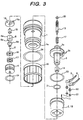
- Fig. 3 is a perspective representing the analyzed component parts.
- a CNG injector is illustrated as the best embodiment. Referring to Fig. 2, the configuration of the engine system for CNG is explained.
- the fuel injection valve 100 for CNG is provided at an intake pipe 101.
- CNG is stored in a tank 102 under a high pressure.
- the pressure of the CNG flowing through a high-pressure pipe 103 is regulated (reduced) by a pressure regulator 104 and the CNG is supplied to an injector 100 through a low-pressure pipe 105.
- the injector 100 is controlled the opening and closing of its valve through a drive unit 107 by electrical signals from an EMC 106 (engine control module; engine control unit).
- the EMC 106 detects the engine operation state according to the signals from a temperature sensor of engine cooling water (not illustrated), an intake pipe pressure sensor 112 and an oxygen sensor arranged on an air flow meter or an exhaust pipe etc..
- the opening time of the CNG injection valve is decided based on these detection signals.
- Numeral 109 denotes a catalyst for CNG.
- the low-pressure pipe 105 is provided with a pressure sensor 112 and an intake air temperature sensor 113.
- the ECM 106 takes these signals in, and calculates and controls the valve opening time of the fuel injection valve 100 in response to the engine operation state.
- the fuel injection valve comprises a casing (yoke) 1, an electromagnetic coil 2, a stationary core 3, a nozzle 4, a movable element 6 (plunger) with a valve body 5, a return spring 7, and a plastic mold 9 with connector pins 8.
- the aforementioned stationary core 3 and electromagnetic coil 2 are arranged inside the casing (the body of an injection valve), and the terminals 11 of the electromagnetic coil 2 are electrically connected with the connector pins 8.
- the electromagnetic coil 2 wound on the bobbin 10 is covered with an external plastic mold 12.
- the stationary core 3 has a hollow cylindrical form, and a flange 3a for covering the upper surface of the external plastic mold of the electromagnetic coil 2 is provided at the outer periphery.
- the terminals 11 are connected via terminal through holes 3b provided at the flange 3a.
- An adjust screw 13 for adjusting the weight of the return spring 7 is provided inside of the top of the stationary core 3.
- An annular concave 3a with the inner diameter portion partially increased is formed on the inner circumferential surface of one end (bottom end) of the stationary core 3.
- a nonmagnetic sleeve-shaped guide (hereinafter referred to as "guide sleeve") 14 for guiding the movement of the movable element 6 is counterlocked into the concave 3a by press fitting or bonding with pressure and plastic deformation (the so called pressure bonding).
- the guide sleeve 14 can be inserted and fixed on the inner circumferential surface of the stationary core 3.
- the guide sleeve 14 is made of a nonmagnetic material having a high hardness of Hv 350 or more.
- JIS SUS 303 or SUS 304 is used as the material, and its surface is provided with wear-proof coating, e.g., Ni-P plating.
- the casing 1 and stationary core 3 are made up of 13Cr based magnetic stainless steel, and the movable element 6 is made of a martensitic stainless steel material such as JIS SUS420J.
- the movable element 6 is connected integrally with the valve body 5 (ball).
- the valve body 5 is made of JIS SUS 440C.
- the movable element 6 is comprised of a valve rod 6b and a hollow cylindrical anchor 6a (also called as a movable core or a plunger) configured integrally.
- the anchor has a larger diameter than the valve rod 6b and its top portion opened.
- a cylindrical guide 15 on the movable element side is fixed inside of the anchor 6a through the open of top portion of the anchor 6a by press fitting or bonding with plastic deformation.
- the guide 15 is partly protruded from the anchor 6a.
- the protrusion of the guide 15 is inserted into the guide sleeve 14 so that sliding of the outer periphery of the protrusion is guided along the inner periphery of the guide sleeve 14.
- the guide 15 is made of a nonmagnetic member of high hardness to ensure wear resistance, similarly to the guide sleeve 14, and is provided with hard coating such as Ni-P plating.
- WCC coating titanium coating or chromium-nitrogen coating may be used for the coating of the guide sleeve 14 and guide 15.
- a curve surface with radius (radius curve profile) 6c of 0.8 mm or more is formed on the boundary (boundary edge) of the outer periphery between the rod 6b and anchor 6a constituting the movable element 6.
- the size of this radius 6c is more than twice as large as that of the conventional gasoline type because of the following reason.
- the liquid membrane is not formed on the surface of the impact parts. Hence it causes a big impact as a result of the impact between the movable element and valve seat at the time of the valve opening-closing motion. If the radius is small, concentrated stress will occur on the boundary edge due to the impact at the time of the valve opening-closing motion, so sufficient durability cannot necessarily be ensured.
- the inventors of the present invention has found out through durability test that, in order to distribute the stress due to impact for ensuring durability, the aforementioned boundary edge 6c should preferably have a radius of 8 mm or more, more preferably a radius of approximately 10 mm. This consideration is incorporated in the present embodiment.
- the movable element 6 of the present embodiment has an overall length of the movable element 6 of about 17 mm, an outer diameter of the anchor 6a of about 6.6 mm, a length of the anchor 6a of 4.65 mm, an outer diameter of the valve rod 6b of about 2.3 mm and an outer diameter of the valve body 5 of about 4.0 mm.
- the side feed method instead of the top feed method is used as a fuel feed method.
- the fuel flows so as to cross the passage (between the casing 1 and magnetic coil external mold 10) inside the injection valve body through the inlet 30 and outlet 33 arranged on the body side surface of the fuel injection valve (side of the casing 1).
- Part of the fuel goes to an injection hole 41 through the passage 32 around the movable element when the valve opens.
- a fuel passage hole (orifice) need not be provided at the anchor, as in the case of top feed method (where fuel passes through into the stationary core of the fuel injection valve from above).
- the structure is suitable for CNG injector.
- the material of the movable element 6 itself is improved in order to enhance resistance to wear and impact; for example, nitriding is provided subsequent to quenching, whereby hardiness is upgraded. Further, to remove the stress in quenching, burnishing is carried out to the movable element.
- the nozzle body 4, stopper 16 and valve guide 17, in addition to the movable element 6, are provided with quenching, nitriding and burnishing, using martensitic stainless steel (e.g. JIS SUS 420J). Nitriding is applied also to the valve body 5.
- the impact load given to the movable element and valve seat at the time of valve opening and closing is 85 kg/cm 2 , for example.
- the depth of the occurrence of the maximum stress at this time is 26 ⁇ m, as shown in Fig. 7 (b).
- the critical Vickers hardness is Hv 670 ⁇ m, as shown by the solid line in Fig. 7 (a).
- the solid line A is a graph, obtained from raw data, representing the relationship between the depth of the occurrence of the maximum stress and critical Vickers hardness.
- the depth of the occurrence of the maximum stress is set at 30 ⁇ m as a result of considering a margin of safety based on the aforementioned experiment data.
- the graph in this case is represented by a solid line B in Fig. 7 (a).
- the hardness of the impact parts is HV 800 or more at a depth of 50 ⁇ m from the top surface, with a margin of safety taken into account. Based on this finding, the movable element 6, nozzle body 4, stopper 16 and valve guide 17 are provided with nitriding in such a way that the aforementioned hardness conditions are met.
- the hardness on the top surface is about HV 1200, for example.
- Each nitriding lamellas formed on the surfaces of the movable element 6, valve body 5, nozzle body 4, stopper 16 and valve guide 17 are provided by low-temperature nitriding at a temperature of 350 through 480°C. This is because of the following reasons. As described above, if the normal nitriding temperature of 500 through 550°C is adopted in the case of a chromium-containing impact-proof material such as martensitic stainless steel, much chromium is precipitated as a nitride from the base material. As a result, the impact resistance (oxidation resistance) of the base material is reduced.
- the nitriding lamella is produced by nitriding treatment at a low temperature of 350 through 480°C to reduce generation of the nitride product by chromium.
- plasma nitriding by direct current glow discharge is used for the nitriding treatment.
- the nozzle body 4 and stopper 16 are attached in the installation hole 1a of the nozzle body 4 provided at the center bottom end of the casing 1.
- This installation hole 1a has a step-shaped surface 1b as a receiving surface of a stopper.
- the stopper 16 sandwiched between the step-shaped surface 1b and the nozzle body 4. Part of the nozzle body is protruded from the installation hole 1a and pressure is given to the edge of the installation hole 1a, whereby the casing 1 and nozzle body 4 are joined with pressure-bonding.
- a valve seat 4c is formed on the inner bottom of the nozzle body 4, and the fuel injection hole 41 (orifice) is made downstream of the valve seat 4c.
- the nozzle body 4 incorporates a valve guide 17 and a guide holder 18 for holding the valve guide in two layers.
- the valve guide 17 and guide holder 18 are formed in the shape of an annular-chip.
- Fuel passages 17a and 18a are provided on the outer periphery of the valve guide 17 and guide holder 18.
- the valve guide 17 is made of martensitic stainless steel of JIS SUS 420J etc.. Similarly to the movable element, it is treated with quenching, nitriding and burnishing in order to increase initial hardness.
- the guide holder 8 is made of a sintered metal, which is not provided with nitriding.
- the edge of outer periphery of the valve guide 17 was locally pressed, whereby the valve guide 17 was pressure-bonded to the inner periphery of the nozzle body 4 by plastic deformation.
- the hardness increases, with the result that pressure bonding with plastic deformation is difficult.
- a guide holder 18 not provided with nitriding is placed on top of the valve guide 17, and the edge of outer periphery of the guide holder 18 is locally pressed so as to cause plastic deformation, whereby the guide holder 18 is pressure-bonded onto the inner periphery of the nozzle body 4. In this manner, the valve guide 17 is held therein by pressure from the guide holder 18.
- Fig. 4 (a) shows the top surface view of the valve guide 17.
- Fig. 4 (b) is a vertical cross sectional view taken on a line corresponding to A-O-A' of Fig. 4 (a).
- Fig. 5 (a) shows the top surface view of the guide holder 18.
- Fig. 5 (b) is a vertical cross sectional view taken on a line corresponding to A-O-A' of Fig. 5 (a).
- valve guide 17 and the guide holder 18 are respectively provided with a plurality of protrusions 17b and 18b (four protrusions in the present embodiment) each protruding in the direction of outer diameter, and these protrusions are arranged at even intervals.
- the grooves 17a and 18a between these protrusions form part of the fuel passage.
- each protrusion 18b of the guide holder 18 has the length in the circumferential direction longer than each protrusion 17b of the valve guide 17 (L 2 > L 1 ).
- the both sides of the protrusion 18b of the guide holder 18 in the circumferential direction protrude more than the both sides of the protrusion 17b of the valve guide 17, as shown in Fig. 5.
- Each Plastic deformation by the aforementioned pressure ranges over the both sides of the protrusion 18b of the guide holder 18, so the plastic deformation reaches both sides of the protrusion 17b of the valve guide 17 in the circumferential direction.
- valve guide 17 is also held by the guide holder 18 in the circumferential direction, hence the valve guide 17 is prevented from moving in the circumferential direction.
- the movable element 6 is provided with a shoulder 6d (stopper on the movable side) that is caught with the stopper 16 when the movable element is moved by electromagnetic attraction (when the valve opens).
- valve body 5 provided at the movable element 6 is guided to the valve seat 4c through the valve guide 17.
- a return spring 7 is located between the guide element 15 on the movable element 6 side and the adjust screw 13.
- the movable element 6 and the valve body 5 are given the force of the return spring 7 toward the valve seat 4c.
- the valve body 5 is pressed by the valve seat 4c, and the valve is kept closed.
- the movable element 6, the movable guide 15 and the valve body 5 are integrally assembled in advance, and the guide sleeve 14 is press-fitted on the inner periphery of the stationary core 3.
- the valve guide 17 and the guide holder 18 are provided into the nozzle body 4.
- Part of the movable element 6, together with the valve body 5, is inserted into the nozzle body 4, and is set in position.
- the nozzle body 4 together with the stopper 16 and movable element 6 is provided with the installation hole 1a located on the bottom end of the casing 1. And the edge of the installation hole 1a is locally deformed by pressure, whereby the casing 1 and nozzle body 4 are bonded together with pressure and plastic deformation.
- the seal ring 24 is mounted in the groove on the outer periphery of the nozzle body 4.
- the electromagnetic coil 2 covered with plastic mold 10, the stationary core 3, the spring 7 and the adjust screw 13 are mounted together with seal rings 20, 21, 22 and 23.
- the terminals 11 of the electromagnetic coil are drawn into the through-holes 3b arranged at the flange of the stationary core 3 through the O-ring 22 and plug 30. After the connector pin 8 has been connected to the terminal 11, the connector mold 9 is formed.
- the seal ring 24 and filter 25 are mounted on the outer periphery of the casing 1.
- the valve guide and the guide holder are provided with a plurality of protrusions protruding in the direction of outer diameter, and these protrusions are arranged at even intervals.
- the groove between these protrusions serves as part of the fuel passage.
- each protrusion of the guide holder has the length in the circumferential direction longer than each protrusion of the valve guide.
- the both sides of the protrusion of the guide holder in the circumferential direction protrude more than the both sides of the protrusion of the valve guide.
- Each Plastic deformation by the aforementioned pressure ranges over the both sides of the protrusion of the guide holder, so the plastic deformation reaches both sides of the protrusion of the valve guide in the circumferential direction.
- a fuel injection valve for internal combustion engine comprises a magnet; a movable element with the valve body opened or closed by this magnet; and a return spring for pressing the valve body in the closing direction of the valve, wherein, when this magnet is energized, the movable element is attracted to the stationary core side by magnetism.
- the fuel injection valve is designed according to the side feed system, wherein the fuel flows so as to cross the passage inside the injection valve body through the inlet and outlet arranged on the side of the body of the fuel injection valve, and part of the fuel is fed into an injection hole by passing around the movable element when the valve opens.
- the aforementioned movable element is composed of a valve rod integrally connected with a hollow anchor having a larger diameter than the valve rod, and a radius of 0.8 mm or more is formed on the boundary between the outer peripheries of the valve rod and anchor.
- nitriding lamellas are formed on the surfaces of one or both of the impact portions between the valve body 5 and valve seat 4c (nozzle body 4), between the valve body 5 and its valve guide 17, and between the stopper 16 and movable element 6; and the sliding section between the movable element 6 and stationary core 3.
- hard coating is provided on the surfaces of the aforementioned nitriding lamellas.
- This hard coating includes CrN coating, for example.
- This coating is provided by activated reaction evaporation (ARE) according to physical vapor deposition (PDV) method characterized by excellent adhesion with the base material, subsequent to plasma nitriding.
- the surface reformed layer of the parts subjected to wear and impact is formed of the nitriding lamella and chromium nickel coating by low temperature nitriding process.
- This arrangement further improves the durability of the CNG-compatible fuel injection valve (resistance to impact, wear and shock).
- a film of about 2 ⁇ m was formed in the formation process using a nitrogen gas as a reaction gas, and chromium Cr as a evaporation substance under a gas pressure of up to 0.13 Pa, with an electron beam power of 5 kW and 140 mA, at a substrate applied voltage of d.c. - 400V and a substrate temperature of up to 400°C, wherein coating process continued for one hour.
- the hard coating formed on the surface of the nitriding lamella is Ni-P plating.
- the fuel injection valve has been descried as a CNG-compatible fuel injection valve.
- the above description can also be applied to a gasoline engine-compatible fuel injection valve.
- the present invention described above improves the shock, wear and impact resistance of the component parts of a fuel injection valve for internal combustion engine using such a gasified fuel as CNG, and provides a fuel injection valve characterized by long-term service life.
Landscapes
- Engineering & Computer Science (AREA)
- Chemical & Material Sciences (AREA)
- Combustion & Propulsion (AREA)
- General Engineering & Computer Science (AREA)
- Mechanical Engineering (AREA)
- General Chemical & Material Sciences (AREA)
- Oil, Petroleum & Natural Gas (AREA)
- Chemical Kinetics & Catalysis (AREA)
- Physics & Mathematics (AREA)
- Electromagnetism (AREA)
- Analytical Chemistry (AREA)
- Manufacturing & Machinery (AREA)
- Fuel-Injection Apparatus (AREA)
Abstract
Description
Claims (9)
- A fuel injection valve comprising:wherein said movable element makes reciprocal motion between said valve seat and said stationary core by the magnetism of said electromagnetic coil and the force of said sleeve;a stationary core;an electromagnetic coil located concentrically with said stationary core;a casing, made of a magnetic material, incorporating said stationary core and electromagnetic coil;a movable element with a valve body;a stopper for said movable element;a valve seat arranged on the opposite side of said stopper in state of locating said movable element between said valve seat and said stopper ; anda spring , engaged with one end of said movable element, for pressing said movable element against said valve seat;
said fuel injection valve further characterized in that a nitriding lamella with impact-proof and wear-proof is formed on the surface of at least one of the wear portions where are also impact portions between the valve body and said valve seat, between said valve body and a valve guide thereof, and between said stopper and a movable element; and where are the sliding section between said movable element and said stationary core. - The fuel injection valve according to Claim 1; wherein said nitriding lamella is formed of a low-temperature nitriding lamella having been nitrided at a temperature of 350 through 480°C.
- The fuel injection valve according to Claim 1 wherein said nitriding lamella has the dept of at least 30 µm and the hardness is at least Hv 800 even at the depth of 30 µm.
- The fuel injection valve according to Claim 1 wherein said nitriding lamella is formed on at least one of a nozzle body equipped with said valve seat, said valve guide, said valve body, said movable element integral with said valve body, and said stopper for determining the stroke of said valve body.
- The fuel injection valve according to Claim 1 wherein a hard coating is formed on the surface of said nitriding lamella.
- An electromagnetic fuel injection valve for an internal combustion engine, wherein the inner circumferential surface of a stationary core constituting part of magnetic circuit is provided with a guide sleeve for guiding the sliding motion of a movable element with a valve body, and said guide sleeve is made of a nonmagnetic member of high hardness, and the surface of said guide sleeve is provided with lamella having a wear-proof.
- The fuel injection valve according to Claim 6, wherein a guide on the movable side whose sliding movement is guided by said guide sleeve is provided on one end of said movable element, and said guide is also composed of a nonmagnetic member of high hardness, and the surface of said guide is provided with lamella having a wear-proof.
- A fuel injection valve for internal combustion engine characterized in that a valve guide in the shape of an annular chip valve guide and its guide holder are incorporated in the nozzle body having a fuel injection hole in layers; said valve guide is made of a metallic material whose surface is nitrided; said guide holder is made of metallic material not provided with nitriding treatment; and the outer edge of said guide holder is subjected to plastic deformation in the nozzle body by the pressure from above, whereby said guide holder is bonded with pressure and plastic deformation on the inner periphery of the nozzle body, and said valve guide is fixed by said guide holder.
- The fuel injection valve of any one of Claims 1 through 8 characterized in that said fuel injection valve is used in a CNG-type internal combustion engine.
Applications Claiming Priority (1)
| Application Number | Priority Date | Filing Date | Title |
|---|---|---|---|
| PCT/JP2001/010056 WO2003042526A1 (en) | 2001-11-16 | 2001-11-16 | Fuel injection valve |
Publications (3)
| Publication Number | Publication Date |
|---|---|
| EP1452717A1 true EP1452717A1 (en) | 2004-09-01 |
| EP1452717A4 EP1452717A4 (en) | 2004-12-29 |
| EP1452717B1 EP1452717B1 (en) | 2007-03-28 |
Family
ID=11737946
Family Applications (1)
| Application Number | Title | Priority Date | Filing Date |
|---|---|---|---|
| EP01274709A Expired - Lifetime EP1452717B1 (en) | 2001-11-16 | 2001-11-16 | Fuel injection valve |
Country Status (5)
| Country | Link |
|---|---|
| US (1) | US20050067512A1 (en) |
| EP (1) | EP1452717B1 (en) |
| JP (1) | JP4011547B2 (en) |
| DE (1) | DE60127594T2 (en) |
| WO (1) | WO2003042526A1 (en) |
Cited By (5)
| Publication number | Priority date | Publication date | Assignee | Title |
|---|---|---|---|---|
| WO2008040581A1 (en) * | 2006-10-04 | 2008-04-10 | A.E.B. S.R.L. | Alternative fuel injector for dual fuel systems |
| WO2009152831A1 (en) * | 2008-06-18 | 2009-12-23 | Fraunhofer-Gesellschaft zur Förderung der angewandten Forschung e.V. | Components comprising a surface coating for gas injection systems (cng+lpg) of internal combustion engines |
| CN104363889A (en) * | 2012-01-27 | 2015-02-18 | 斯特布尔药业有限责任公司 | Improved injections |
| WO2016034339A1 (en) * | 2014-09-02 | 2016-03-10 | Robert Bosch Gmbh | Valve and method for producing a valve |
| WO2016050506A1 (en) * | 2014-10-02 | 2016-04-07 | Continental Automotive Gmbh | Fuel injection valve and method for producing same |
Families Citing this family (19)
| Publication number | Priority date | Publication date | Assignee | Title |
|---|---|---|---|---|
| US7673847B2 (en) * | 2005-09-21 | 2010-03-09 | Aisan Kogyo Kabushiki Kaisha | Fluid control valve for supplying gas to a fuel cell in a vehicle |
| DE102006027614B4 (en) * | 2006-06-13 | 2009-02-05 | L'orange Gmbh | Injection injector for internal combustion engines |
| DE102006052817A1 (en) * | 2006-11-09 | 2008-05-15 | Robert Bosch Gmbh | Fuel injection valve for e.g. direct injection of fuel into combustion chamber of internal combustion engine, has valve seat body and closing body provided with rigidity-reducing element that is designed as recess i.e. circulating groove |
| US20090087673A1 (en) * | 2007-09-28 | 2009-04-02 | Taylor Steven C | Method for coating fuel system components |
| JP4420102B2 (en) * | 2007-10-30 | 2010-02-24 | 株式会社デンソー | Injector |
| JP4492696B2 (en) * | 2007-12-25 | 2010-06-30 | 株式会社デンソー | Fuel injection valve |
| JP5142859B2 (en) * | 2008-07-07 | 2013-02-13 | 株式会社ケーヒン | Electromagnetic fuel injection valve |
| US7886718B2 (en) * | 2008-09-26 | 2011-02-15 | Caterpillar Inc. | Fuel injector having integral body guide and nozzle case for pressure containment |
| JP5623784B2 (en) * | 2010-05-14 | 2014-11-12 | 株式会社ケーヒン | Electromagnetic fuel injection valve |
| JP5862941B2 (en) * | 2011-11-08 | 2016-02-16 | 株式会社デンソー | Fuel injection valve |
| JP5822269B2 (en) * | 2011-11-11 | 2015-11-24 | 株式会社ケーヒン | Electromagnetic fuel injection valve |
| CN102493895A (en) * | 2011-12-27 | 2012-06-13 | 北京爱尼机电有限公司 | Compressed natural gas ejector |
| RU2554169C1 (en) * | 2014-04-02 | 2015-06-27 | Алексей Михайлович Харченков | Gaseous fuel supply injector |
| DK178427B1 (en) * | 2015-04-29 | 2016-02-22 | Hans Jensen Lubricators As | Lubricant injector for large slow-running two-stroke engine and production method |
| DK179001B1 (en) * | 2016-03-09 | 2017-08-07 | Man Diesel & Turbo Filial Af Man Diesel & Turbo Se Tyskland | Engine device of an internal combustion engine |
| WO2021154360A1 (en) * | 2020-01-30 | 2021-08-05 | Cummins Inc. | Two-stage gas nitriding process for improved wear and erosion resistance |
| CN115735054B (en) * | 2020-06-24 | 2025-12-09 | 贺尔碧格维恩有限公司 | Electromagnetic valve |
| JP7724495B2 (en) * | 2021-07-27 | 2025-08-18 | 三菱重工エンジン&ターボチャージャ株式会社 | Solenoid device and solenoid valve of fuel injection device |
| FR3164254A1 (en) * | 2024-07-03 | 2026-01-09 | Phinia Delphi Luxembourg Sarl | INJECTOR FOR ALTERNATIVE FUEL |
Family Cites Families (13)
| Publication number | Priority date | Publication date | Assignee | Title |
|---|---|---|---|---|
| US4231525A (en) * | 1979-05-10 | 1980-11-04 | General Motors Corporation | Electromagnetic fuel injector with selectively hardened armature |
| US4311280A (en) * | 1980-07-21 | 1982-01-19 | General Motors Corporation | Electromagnetic fuel injector with adjustable armature spring |
| DE3878599T2 (en) * | 1987-06-26 | 1993-09-23 | Hitachi Automotive Eng | ELECTROMAGNETIC FUEL INJECTION VALVE. |
| US5514064A (en) * | 1987-08-20 | 1996-05-07 | Della Torre; Renato | Process and means for making metal inking rolls |
| JP2708470B2 (en) * | 1988-06-08 | 1998-02-04 | 株式会社日立製作所 | Electromagnetic fuel injection valve |
| JP3052525B2 (en) * | 1992-01-30 | 2000-06-12 | 株式会社日立製作所 | Processing method of electromagnetic fuel injection valve |
| JPH0754732A (en) * | 1993-08-18 | 1995-02-28 | Yamaha Motor Co Ltd | Valve body support structure for fuel injection valve |
| JPH07197352A (en) * | 1993-12-29 | 1995-08-01 | Daido Hoxan Inc | Corrosion-resistant dent for loom |
| DE4421937C1 (en) * | 1994-06-23 | 1995-12-21 | Bosch Gmbh Robert | Method for treating at least one part made of soft magnetic wear-resistant part and its use |
| DE19526387C2 (en) * | 1994-07-19 | 1998-12-10 | Sumitomo Metal Mining Co | Double-coated composite steel article and method for its production |
| JP3352889B2 (en) * | 1996-10-16 | 2002-12-03 | 山陽特殊製鋼株式会社 | Hot tool steel with excellent nitriding properties |
| JP2001050133A (en) * | 1999-08-06 | 2001-02-23 | Hitachi Ltd | Electronic fuel injection valve |
| US6758421B1 (en) * | 2000-03-31 | 2004-07-06 | Siemens Automotive Corporation | Double concentric inlet tube for setting armature/needle lift and method of manufacturing same |
-
2001
- 2001-11-16 DE DE60127594T patent/DE60127594T2/en not_active Expired - Fee Related
- 2001-11-16 EP EP01274709A patent/EP1452717B1/en not_active Expired - Lifetime
- 2001-11-16 JP JP2003544326A patent/JP4011547B2/en not_active Expired - Fee Related
- 2001-11-16 WO PCT/JP2001/010056 patent/WO2003042526A1/en not_active Ceased
- 2001-11-16 US US10/495,566 patent/US20050067512A1/en not_active Abandoned
Cited By (10)
| Publication number | Priority date | Publication date | Assignee | Title |
|---|---|---|---|---|
| WO2008040581A1 (en) * | 2006-10-04 | 2008-04-10 | A.E.B. S.R.L. | Alternative fuel injector for dual fuel systems |
| CN101542104B (en) * | 2006-10-04 | 2012-11-07 | A.E.B.有限公司 | Optional fuel injectors for dual fuel systems |
| AU2007304380B2 (en) * | 2006-10-04 | 2013-08-15 | A.E.B. S.R.L. | Alternative fuel injector for dual fuel systems |
| WO2009152831A1 (en) * | 2008-06-18 | 2009-12-23 | Fraunhofer-Gesellschaft zur Förderung der angewandten Forschung e.V. | Components comprising a surface coating for gas injection systems (cng+lpg) of internal combustion engines |
| CN104363889A (en) * | 2012-01-27 | 2015-02-18 | 斯特布尔药业有限责任公司 | Improved injections |
| WO2016034339A1 (en) * | 2014-09-02 | 2016-03-10 | Robert Bosch Gmbh | Valve and method for producing a valve |
| CN106662057A (en) * | 2014-09-02 | 2017-05-10 | 罗伯特·博世有限公司 | Valve and method for producing a valve |
| US10415526B2 (en) | 2014-09-02 | 2019-09-17 | Robert Bosch Gmbh | Valve and method for producing a valve |
| US11060494B2 (en) | 2014-09-02 | 2021-07-13 | Robert Bosch Gmbh | Valve and method for producing a valve |
| WO2016050506A1 (en) * | 2014-10-02 | 2016-04-07 | Continental Automotive Gmbh | Fuel injection valve and method for producing same |
Also Published As
| Publication number | Publication date |
|---|---|
| WO2003042526A1 (en) | 2003-05-22 |
| US20050067512A1 (en) | 2005-03-31 |
| JP4011547B2 (en) | 2007-11-21 |
| EP1452717B1 (en) | 2007-03-28 |
| JPWO2003042526A1 (en) | 2005-03-10 |
| DE60127594D1 (en) | 2007-05-10 |
| EP1452717A4 (en) | 2004-12-29 |
| DE60127594T2 (en) | 2008-01-24 |
Similar Documents
| Publication | Publication Date | Title |
|---|---|---|
| EP1452717B1 (en) | Fuel injection valve | |
| US7481378B2 (en) | Polymeric bodied fuel injector | |
| US8113177B2 (en) | Electromagnetic fuel injector and method for assembling the same | |
| US7506826B2 (en) | Injection valve with a corrosion-inhibiting, wear-resistant coating and method for the production thereof | |
| JP5239965B2 (en) | Fuel injection valve | |
| US6336621B1 (en) | Electromagnetic fuel injection valve | |
| US20120204839A1 (en) | Electromagnetic fuel injection valve | |
| US20070228193A1 (en) | Fuel injector | |
| US6752374B2 (en) | Electromagnetic valve and method of manufacturing same | |
| JP2002106740A (en) | Solenoid valve and high-pressure pump using the same | |
| JP2017141840A (en) | Fuel injection valve | |
| JP2018087548A (en) | High pressure fuel supply pump | |
| US20040026541A1 (en) | Fuel injection valve | |
| US8616473B2 (en) | High flow compressed natural gas injector for automotive applications | |
| JP2007182903A (en) | Fuel injection valve | |
| JP4070525B2 (en) | Solenoid valve and manufacturing method thereof | |
| JP2002349745A (en) | solenoid valve |
Legal Events
| Date | Code | Title | Description |
|---|---|---|---|
| PUAI | Public reference made under article 153(3) epc to a published international application that has entered the european phase |
Free format text: ORIGINAL CODE: 0009012 |
|
| 17P | Request for examination filed |
Effective date: 20040607 |
|
| AK | Designated contracting states |
Kind code of ref document: A1 Designated state(s): AT BE CH CY DE DK ES FI FR GB GR IE IT LI LU MC NL PT SE TR |
|
| A4 | Supplementary search report drawn up and despatched |
Effective date: 20041115 |
|
| RIC1 | Information provided on ipc code assigned before grant |
Ipc: 7F 02M 51/06 B Ipc: 7F 02M 61/04 B Ipc: 7F 02M 61/12 B Ipc: 7C 23C 8/38 B Ipc: 7F 02M 21/02 A Ipc: 7F 02M 51/08 B Ipc: 7F 02M 61/16 B |
|
| 17Q | First examination report despatched |
Effective date: 20041220 |
|
| GRAP | Despatch of communication of intention to grant a patent |
Free format text: ORIGINAL CODE: EPIDOSNIGR1 |
|
| GRAS | Grant fee paid |
Free format text: ORIGINAL CODE: EPIDOSNIGR3 |
|
| GRAA | (expected) grant |
Free format text: ORIGINAL CODE: 0009210 |
|
| RAP1 | Party data changed (applicant data changed or rights of an application transferred) |
Owner name: HITACHI CAR ENGINEERING CO., LTD. Owner name: HITACHI, LTD. |
|
| AK | Designated contracting states |
Kind code of ref document: B1 Designated state(s): DE |
|
| REF | Corresponds to: |
Ref document number: 60127594 Country of ref document: DE Date of ref document: 20070510 Kind code of ref document: P |
|
| PLBE | No opposition filed within time limit |
Free format text: ORIGINAL CODE: 0009261 |
|
| STAA | Information on the status of an ep patent application or granted ep patent |
Free format text: STATUS: NO OPPOSITION FILED WITHIN TIME LIMIT |
|
| 26N | No opposition filed |
Effective date: 20080102 |
|
| PGFP | Annual fee paid to national office [announced via postgrant information from national office to epo] |
Ref country code: DE Payment date: 20081126 Year of fee payment: 8 |
|
| PG25 | Lapsed in a contracting state [announced via postgrant information from national office to epo] |
Ref country code: DE Free format text: LAPSE BECAUSE OF NON-PAYMENT OF DUE FEES Effective date: 20100601 |