EP1452511A1 - Honeycomb structure body and method for manufacturing the same - Google Patents
Honeycomb structure body and method for manufacturing the same Download PDFInfo
- Publication number
- EP1452511A1 EP1452511A1 EP02783763A EP02783763A EP1452511A1 EP 1452511 A1 EP1452511 A1 EP 1452511A1 EP 02783763 A EP02783763 A EP 02783763A EP 02783763 A EP02783763 A EP 02783763A EP 1452511 A1 EP1452511 A1 EP 1452511A1
- Authority
- EP
- European Patent Office
- Prior art keywords
- honeycomb
- layer
- cement
- undercoat
- segment
- Prior art date
- Legal status (The legal status is an assumption and is not a legal conclusion. Google has not performed a legal analysis and makes no representation as to the accuracy of the status listed.)
- Granted
Links
Images


Classifications
-
- C—CHEMISTRY; METALLURGY
- C04—CEMENTS; CONCRETE; ARTIFICIAL STONE; CERAMICS; REFRACTORIES
- C04B—LIME, MAGNESIA; SLAG; CEMENTS; COMPOSITIONS THEREOF, e.g. MORTARS, CONCRETE OR LIKE BUILDING MATERIALS; ARTIFICIAL STONE; CERAMICS; REFRACTORIES; TREATMENT OF NATURAL STONE
- C04B28/00—Compositions of mortars, concrete or artificial stone, containing inorganic binders or the reaction product of an inorganic and an organic binder, e.g. polycarboxylate cements
- C04B28/24—Compositions of mortars, concrete or artificial stone, containing inorganic binders or the reaction product of an inorganic and an organic binder, e.g. polycarboxylate cements containing alkyl, ammonium or metal silicates; containing silica sols
-
- B—PERFORMING OPERATIONS; TRANSPORTING
- B01—PHYSICAL OR CHEMICAL PROCESSES OR APPARATUS IN GENERAL
- B01D—SEPARATION
- B01D46/00—Filters or filtering processes specially modified for separating dispersed particles from gases or vapours
- B01D46/0001—Making filtering elements
-
- B—PERFORMING OPERATIONS; TRANSPORTING
- B01—PHYSICAL OR CHEMICAL PROCESSES OR APPARATUS IN GENERAL
- B01D—SEPARATION
- B01D46/00—Filters or filtering processes specially modified for separating dispersed particles from gases or vapours
- B01D46/24—Particle separators, e.g. dust precipitators, using rigid hollow filter bodies
- B01D46/2403—Particle separators, e.g. dust precipitators, using rigid hollow filter bodies characterised by the physical shape or structure of the filtering element
- B01D46/2418—Honeycomb filters
- B01D46/2425—Honeycomb filters characterized by parameters related to the physical properties of the honeycomb structure material
- B01D46/2429—Honeycomb filters characterized by parameters related to the physical properties of the honeycomb structure material of the honeycomb walls or cells
-
- B—PERFORMING OPERATIONS; TRANSPORTING
- B01—PHYSICAL OR CHEMICAL PROCESSES OR APPARATUS IN GENERAL
- B01D—SEPARATION
- B01D46/00—Filters or filtering processes specially modified for separating dispersed particles from gases or vapours
- B01D46/24—Particle separators, e.g. dust precipitators, using rigid hollow filter bodies
- B01D46/2403—Particle separators, e.g. dust precipitators, using rigid hollow filter bodies characterised by the physical shape or structure of the filtering element
- B01D46/2418—Honeycomb filters
- B01D46/2425—Honeycomb filters characterized by parameters related to the physical properties of the honeycomb structure material
- B01D46/2448—Honeycomb filters characterized by parameters related to the physical properties of the honeycomb structure material of the adhesive layers, i.e. joints between segments
-
- B—PERFORMING OPERATIONS; TRANSPORTING
- B01—PHYSICAL OR CHEMICAL PROCESSES OR APPARATUS IN GENERAL
- B01D—SEPARATION
- B01D46/00—Filters or filtering processes specially modified for separating dispersed particles from gases or vapours
- B01D46/24—Particle separators, e.g. dust precipitators, using rigid hollow filter bodies
- B01D46/2403—Particle separators, e.g. dust precipitators, using rigid hollow filter bodies characterised by the physical shape or structure of the filtering element
- B01D46/2418—Honeycomb filters
- B01D46/2425—Honeycomb filters characterized by parameters related to the physical properties of the honeycomb structure material
- B01D46/24494—Thermal expansion coefficient, heat capacity or thermal conductivity
-
- B—PERFORMING OPERATIONS; TRANSPORTING
- B01—PHYSICAL OR CHEMICAL PROCESSES OR APPARATUS IN GENERAL
- B01D—SEPARATION
- B01D46/00—Filters or filtering processes specially modified for separating dispersed particles from gases or vapours
- B01D46/24—Particle separators, e.g. dust precipitators, using rigid hollow filter bodies
- B01D46/2403—Particle separators, e.g. dust precipitators, using rigid hollow filter bodies characterised by the physical shape or structure of the filtering element
- B01D46/2418—Honeycomb filters
- B01D46/2451—Honeycomb filters characterized by the geometrical structure, shape, pattern or configuration or parameters related to the geometry of the structure
- B01D46/2478—Structures comprising honeycomb segments
-
- B—PERFORMING OPERATIONS; TRANSPORTING
- B01—PHYSICAL OR CHEMICAL PROCESSES OR APPARATUS IN GENERAL
- B01D—SEPARATION
- B01D53/00—Separation of gases or vapours; Recovering vapours of volatile solvents from gases; Chemical or biological purification of waste gases, e.g. engine exhaust gases, smoke, fumes, flue gases, aerosols
- B01D53/34—Chemical or biological purification of waste gases
- B01D53/74—General processes for purification of waste gases; Apparatus or devices specially adapted therefor
- B01D53/86—Catalytic processes
- B01D53/88—Handling or mounting catalysts
- B01D53/885—Devices in general for catalytic purification of waste gases
-
- B—PERFORMING OPERATIONS; TRANSPORTING
- B01—PHYSICAL OR CHEMICAL PROCESSES OR APPARATUS IN GENERAL
- B01D—SEPARATION
- B01D53/00—Separation of gases or vapours; Recovering vapours of volatile solvents from gases; Chemical or biological purification of waste gases, e.g. engine exhaust gases, smoke, fumes, flue gases, aerosols
- B01D53/34—Chemical or biological purification of waste gases
- B01D53/92—Chemical or biological purification of waste gases of engine exhaust gases
- B01D53/94—Chemical or biological purification of waste gases of engine exhaust gases by catalytic processes
-
- B—PERFORMING OPERATIONS; TRANSPORTING
- B01—PHYSICAL OR CHEMICAL PROCESSES OR APPARATUS IN GENERAL
- B01J—CHEMICAL OR PHYSICAL PROCESSES, e.g. CATALYSIS OR COLLOID CHEMISTRY; THEIR RELEVANT APPARATUS
- B01J35/00—Catalysts, in general, characterised by their form or physical properties
- B01J35/50—Catalysts, in general, characterised by their form or physical properties characterised by their shape or configuration
- B01J35/56—Foraminous structures having flow-through passages or channels, e.g. grids or three-dimensional [3D] monoliths
- B01J35/57—Honeycombs
-
- B—PERFORMING OPERATIONS; TRANSPORTING
- B01—PHYSICAL OR CHEMICAL PROCESSES OR APPARATUS IN GENERAL
- B01J—CHEMICAL OR PHYSICAL PROCESSES, e.g. CATALYSIS OR COLLOID CHEMISTRY; THEIR RELEVANT APPARATUS
- B01J37/00—Processes, in general, for preparing catalysts; Processes, in general, for activation of catalysts
- B01J37/02—Impregnation, coating or precipitation
- B01J37/024—Multiple impregnation or coating
- B01J37/0244—Coatings comprising several layers
-
- B—PERFORMING OPERATIONS; TRANSPORTING
- B28—WORKING CEMENT, CLAY, OR STONE
- B28B—SHAPING CLAY OR OTHER CERAMIC COMPOSITIONS; SHAPING SLAG; SHAPING MIXTURES CONTAINING CEMENTITIOUS MATERIAL, e.g. PLASTER
- B28B1/00—Producing shaped prefabricated articles from the material
- B28B1/002—Producing shaped prefabricated articles from the material assembled from preformed elements
-
- C—CHEMISTRY; METALLURGY
- C04—CEMENTS; CONCRETE; ARTIFICIAL STONE; CERAMICS; REFRACTORIES
- C04B—LIME, MAGNESIA; SLAG; CEMENTS; COMPOSITIONS THEREOF, e.g. MORTARS, CONCRETE OR LIKE BUILDING MATERIALS; ARTIFICIAL STONE; CERAMICS; REFRACTORIES; TREATMENT OF NATURAL STONE
- C04B35/00—Shaped ceramic products characterised by their composition; Ceramics compositions; Processing powders of inorganic compounds preparatory to the manufacturing of ceramic products
- C04B35/515—Shaped ceramic products characterised by their composition; Ceramics compositions; Processing powders of inorganic compounds preparatory to the manufacturing of ceramic products based on non-oxide ceramics
- C04B35/56—Shaped ceramic products characterised by their composition; Ceramics compositions; Processing powders of inorganic compounds preparatory to the manufacturing of ceramic products based on non-oxide ceramics based on carbides or oxycarbides
- C04B35/565—Shaped ceramic products characterised by their composition; Ceramics compositions; Processing powders of inorganic compounds preparatory to the manufacturing of ceramic products based on non-oxide ceramics based on carbides or oxycarbides based on silicon carbide
-
- C—CHEMISTRY; METALLURGY
- C04—CEMENTS; CONCRETE; ARTIFICIAL STONE; CERAMICS; REFRACTORIES
- C04B—LIME, MAGNESIA; SLAG; CEMENTS; COMPOSITIONS THEREOF, e.g. MORTARS, CONCRETE OR LIKE BUILDING MATERIALS; ARTIFICIAL STONE; CERAMICS; REFRACTORIES; TREATMENT OF NATURAL STONE
- C04B35/00—Shaped ceramic products characterised by their composition; Ceramics compositions; Processing powders of inorganic compounds preparatory to the manufacturing of ceramic products
- C04B35/622—Forming processes; Processing powders of inorganic compounds preparatory to the manufacturing of ceramic products
- C04B35/626—Preparing or treating the powders individually or as batches ; preparing or treating macroscopic reinforcing agents for ceramic products, e.g. fibres; mechanical aspects section B
- C04B35/62605—Treating the starting powders individually or as mixtures
- C04B35/62625—Wet mixtures
-
- C—CHEMISTRY; METALLURGY
- C04—CEMENTS; CONCRETE; ARTIFICIAL STONE; CERAMICS; REFRACTORIES
- C04B—LIME, MAGNESIA; SLAG; CEMENTS; COMPOSITIONS THEREOF, e.g. MORTARS, CONCRETE OR LIKE BUILDING MATERIALS; ARTIFICIAL STONE; CERAMICS; REFRACTORIES; TREATMENT OF NATURAL STONE
- C04B35/00—Shaped ceramic products characterised by their composition; Ceramics compositions; Processing powders of inorganic compounds preparatory to the manufacturing of ceramic products
- C04B35/71—Ceramic products containing macroscopic reinforcing agents
- C04B35/78—Ceramic products containing macroscopic reinforcing agents containing non-metallic materials
- C04B35/80—Fibres, filaments, whiskers, platelets, or the like
-
- C—CHEMISTRY; METALLURGY
- C04—CEMENTS; CONCRETE; ARTIFICIAL STONE; CERAMICS; REFRACTORIES
- C04B—LIME, MAGNESIA; SLAG; CEMENTS; COMPOSITIONS THEREOF, e.g. MORTARS, CONCRETE OR LIKE BUILDING MATERIALS; ARTIFICIAL STONE; CERAMICS; REFRACTORIES; TREATMENT OF NATURAL STONE
- C04B37/00—Joining burned ceramic articles with other burned ceramic articles or other articles by heating
- C04B37/003—Joining burned ceramic articles with other burned ceramic articles or other articles by heating by means of an interlayer consisting of a combination of materials selected from glass, or ceramic material with metals, metal oxides or metal salts
- C04B37/005—Joining burned ceramic articles with other burned ceramic articles or other articles by heating by means of an interlayer consisting of a combination of materials selected from glass, or ceramic material with metals, metal oxides or metal salts consisting of glass or ceramic material
-
- C—CHEMISTRY; METALLURGY
- C04—CEMENTS; CONCRETE; ARTIFICIAL STONE; CERAMICS; REFRACTORIES
- C04B—LIME, MAGNESIA; SLAG; CEMENTS; COMPOSITIONS THEREOF, e.g. MORTARS, CONCRETE OR LIKE BUILDING MATERIALS; ARTIFICIAL STONE; CERAMICS; REFRACTORIES; TREATMENT OF NATURAL STONE
- C04B38/00—Porous mortars, concrete, artificial stone or ceramic ware; Preparation thereof
- C04B38/0006—Honeycomb structures
-
- F—MECHANICAL ENGINEERING; LIGHTING; HEATING; WEAPONS; BLASTING
- F01—MACHINES OR ENGINES IN GENERAL; ENGINE PLANTS IN GENERAL; STEAM ENGINES
- F01N—GAS-FLOW SILENCERS OR EXHAUST APPARATUS FOR MACHINES OR ENGINES IN GENERAL; GAS-FLOW SILENCERS OR EXHAUST APPARATUS FOR INTERNAL-COMBUSTION ENGINES
- F01N3/00—Exhaust or silencing apparatus having means for purifying, rendering innocuous, or otherwise treating exhaust
- F01N3/02—Exhaust or silencing apparatus having means for purifying, rendering innocuous, or otherwise treating exhaust for cooling, or for removing solid constituents of, exhaust
- F01N3/021—Exhaust or silencing apparatus having means for purifying, rendering innocuous, or otherwise treating exhaust for cooling, or for removing solid constituents of, exhaust by means of filters
- F01N3/0211—Arrangements for mounting filtering elements in housing, e.g. with means for compensating thermal expansion or vibration
-
- F—MECHANICAL ENGINEERING; LIGHTING; HEATING; WEAPONS; BLASTING
- F01—MACHINES OR ENGINES IN GENERAL; ENGINE PLANTS IN GENERAL; STEAM ENGINES
- F01N—GAS-FLOW SILENCERS OR EXHAUST APPARATUS FOR MACHINES OR ENGINES IN GENERAL; GAS-FLOW SILENCERS OR EXHAUST APPARATUS FOR INTERNAL-COMBUSTION ENGINES
- F01N3/00—Exhaust or silencing apparatus having means for purifying, rendering innocuous, or otherwise treating exhaust
- F01N3/02—Exhaust or silencing apparatus having means for purifying, rendering innocuous, or otherwise treating exhaust for cooling, or for removing solid constituents of, exhaust
- F01N3/021—Exhaust or silencing apparatus having means for purifying, rendering innocuous, or otherwise treating exhaust for cooling, or for removing solid constituents of, exhaust by means of filters
- F01N3/022—Exhaust or silencing apparatus having means for purifying, rendering innocuous, or otherwise treating exhaust for cooling, or for removing solid constituents of, exhaust by means of filters characterised by specially adapted filtering structure, e.g. honeycomb, mesh or fibrous
- F01N3/0222—Exhaust or silencing apparatus having means for purifying, rendering innocuous, or otherwise treating exhaust for cooling, or for removing solid constituents of, exhaust by means of filters characterised by specially adapted filtering structure, e.g. honeycomb, mesh or fibrous the structure being monolithic, e.g. honeycombs
-
- F—MECHANICAL ENGINEERING; LIGHTING; HEATING; WEAPONS; BLASTING
- F01—MACHINES OR ENGINES IN GENERAL; ENGINE PLANTS IN GENERAL; STEAM ENGINES
- F01N—GAS-FLOW SILENCERS OR EXHAUST APPARATUS FOR MACHINES OR ENGINES IN GENERAL; GAS-FLOW SILENCERS OR EXHAUST APPARATUS FOR INTERNAL-COMBUSTION ENGINES
- F01N3/00—Exhaust or silencing apparatus having means for purifying, rendering innocuous, or otherwise treating exhaust
- F01N3/02—Exhaust or silencing apparatus having means for purifying, rendering innocuous, or otherwise treating exhaust for cooling, or for removing solid constituents of, exhaust
- F01N3/021—Exhaust or silencing apparatus having means for purifying, rendering innocuous, or otherwise treating exhaust for cooling, or for removing solid constituents of, exhaust by means of filters
- F01N3/033—Exhaust or silencing apparatus having means for purifying, rendering innocuous, or otherwise treating exhaust for cooling, or for removing solid constituents of, exhaust by means of filters in combination with other devices
- F01N3/035—Exhaust or silencing apparatus having means for purifying, rendering innocuous, or otherwise treating exhaust for cooling, or for removing solid constituents of, exhaust by means of filters in combination with other devices with catalytic reactors
-
- F—MECHANICAL ENGINEERING; LIGHTING; HEATING; WEAPONS; BLASTING
- F01—MACHINES OR ENGINES IN GENERAL; ENGINE PLANTS IN GENERAL; STEAM ENGINES
- F01N—GAS-FLOW SILENCERS OR EXHAUST APPARATUS FOR MACHINES OR ENGINES IN GENERAL; GAS-FLOW SILENCERS OR EXHAUST APPARATUS FOR INTERNAL-COMBUSTION ENGINES
- F01N3/00—Exhaust or silencing apparatus having means for purifying, rendering innocuous, or otherwise treating exhaust
- F01N3/08—Exhaust or silencing apparatus having means for purifying, rendering innocuous, or otherwise treating exhaust for rendering innocuous
- F01N3/10—Exhaust or silencing apparatus having means for purifying, rendering innocuous, or otherwise treating exhaust for rendering innocuous by thermal or catalytic conversion of noxious components of exhaust
- F01N3/24—Exhaust or silencing apparatus having means for purifying, rendering innocuous, or otherwise treating exhaust for rendering innocuous by thermal or catalytic conversion of noxious components of exhaust characterised by constructional aspects of converting apparatus
- F01N3/28—Construction of catalytic reactors
- F01N3/2803—Construction of catalytic reactors characterised by structure, by material or by manufacturing of catalyst support
-
- B—PERFORMING OPERATIONS; TRANSPORTING
- B01—PHYSICAL OR CHEMICAL PROCESSES OR APPARATUS IN GENERAL
- B01D—SEPARATION
- B01D46/00—Filters or filtering processes specially modified for separating dispersed particles from gases or vapours
- B01D46/24—Particle separators, e.g. dust precipitators, using rigid hollow filter bodies
- B01D46/2403—Particle separators, e.g. dust precipitators, using rigid hollow filter bodies characterised by the physical shape or structure of the filtering element
- B01D46/2418—Honeycomb filters
- B01D46/2498—The honeycomb filter being defined by mathematical relationships
-
- B—PERFORMING OPERATIONS; TRANSPORTING
- B32—LAYERED PRODUCTS
- B32B—LAYERED PRODUCTS, i.e. PRODUCTS BUILT-UP OF STRATA OF FLAT OR NON-FLAT, e.g. CELLULAR OR HONEYCOMB, FORM
- B32B2315/00—Other materials containing non-metallic inorganic compounds not provided for in groups B32B2311/00 - B32B2313/04
- B32B2315/02—Ceramics
-
- C—CHEMISTRY; METALLURGY
- C04—CEMENTS; CONCRETE; ARTIFICIAL STONE; CERAMICS; REFRACTORIES
- C04B—LIME, MAGNESIA; SLAG; CEMENTS; COMPOSITIONS THEREOF, e.g. MORTARS, CONCRETE OR LIKE BUILDING MATERIALS; ARTIFICIAL STONE; CERAMICS; REFRACTORIES; TREATMENT OF NATURAL STONE
- C04B2111/00—Mortars, concrete or artificial stone or mixtures to prepare them, characterised by specific function, property or use
- C04B2111/00474—Uses not provided for elsewhere in C04B2111/00
- C04B2111/00793—Uses not provided for elsewhere in C04B2111/00 as filters or diaphragms
-
- C—CHEMISTRY; METALLURGY
- C04—CEMENTS; CONCRETE; ARTIFICIAL STONE; CERAMICS; REFRACTORIES
- C04B—LIME, MAGNESIA; SLAG; CEMENTS; COMPOSITIONS THEREOF, e.g. MORTARS, CONCRETE OR LIKE BUILDING MATERIALS; ARTIFICIAL STONE; CERAMICS; REFRACTORIES; TREATMENT OF NATURAL STONE
- C04B2235/00—Aspects relating to ceramic starting mixtures or sintered ceramic products
- C04B2235/02—Composition of constituents of the starting material or of secondary phases of the final product
- C04B2235/30—Constituents and secondary phases not being of a fibrous nature
- C04B2235/34—Non-metal oxides, non-metal mixed oxides, or salts thereof that form the non-metal oxides upon heating, e.g. carbonates, nitrates, (oxy)hydroxides, chlorides
- C04B2235/3418—Silicon oxide, silicic acids or oxide forming salts thereof, e.g. silica sol, fused silica, silica fume, cristobalite, quartz or flint
-
- C—CHEMISTRY; METALLURGY
- C04—CEMENTS; CONCRETE; ARTIFICIAL STONE; CERAMICS; REFRACTORIES
- C04B—LIME, MAGNESIA; SLAG; CEMENTS; COMPOSITIONS THEREOF, e.g. MORTARS, CONCRETE OR LIKE BUILDING MATERIALS; ARTIFICIAL STONE; CERAMICS; REFRACTORIES; TREATMENT OF NATURAL STONE
- C04B2235/00—Aspects relating to ceramic starting mixtures or sintered ceramic products
- C04B2235/02—Composition of constituents of the starting material or of secondary phases of the final product
- C04B2235/30—Constituents and secondary phases not being of a fibrous nature
- C04B2235/38—Non-oxide ceramic constituents or additives
- C04B2235/3817—Carbides
- C04B2235/3826—Silicon carbides
-
- C—CHEMISTRY; METALLURGY
- C04—CEMENTS; CONCRETE; ARTIFICIAL STONE; CERAMICS; REFRACTORIES
- C04B—LIME, MAGNESIA; SLAG; CEMENTS; COMPOSITIONS THEREOF, e.g. MORTARS, CONCRETE OR LIKE BUILDING MATERIALS; ARTIFICIAL STONE; CERAMICS; REFRACTORIES; TREATMENT OF NATURAL STONE
- C04B2235/00—Aspects relating to ceramic starting mixtures or sintered ceramic products
- C04B2235/02—Composition of constituents of the starting material or of secondary phases of the final product
- C04B2235/30—Constituents and secondary phases not being of a fibrous nature
- C04B2235/42—Non metallic elements added as constituents or additives, e.g. sulfur, phosphor, selenium or tellurium
- C04B2235/428—Silicon
-
- C—CHEMISTRY; METALLURGY
- C04—CEMENTS; CONCRETE; ARTIFICIAL STONE; CERAMICS; REFRACTORIES
- C04B—LIME, MAGNESIA; SLAG; CEMENTS; COMPOSITIONS THEREOF, e.g. MORTARS, CONCRETE OR LIKE BUILDING MATERIALS; ARTIFICIAL STONE; CERAMICS; REFRACTORIES; TREATMENT OF NATURAL STONE
- C04B2235/00—Aspects relating to ceramic starting mixtures or sintered ceramic products
- C04B2235/02—Composition of constituents of the starting material or of secondary phases of the final product
- C04B2235/50—Constituents or additives of the starting mixture chosen for their shape or used because of their shape or their physical appearance
- C04B2235/52—Constituents or additives characterised by their shapes
- C04B2235/5208—Fibers
- C04B2235/5216—Inorganic
-
- C—CHEMISTRY; METALLURGY
- C04—CEMENTS; CONCRETE; ARTIFICIAL STONE; CERAMICS; REFRACTORIES
- C04B—LIME, MAGNESIA; SLAG; CEMENTS; COMPOSITIONS THEREOF, e.g. MORTARS, CONCRETE OR LIKE BUILDING MATERIALS; ARTIFICIAL STONE; CERAMICS; REFRACTORIES; TREATMENT OF NATURAL STONE
- C04B2235/00—Aspects relating to ceramic starting mixtures or sintered ceramic products
- C04B2235/70—Aspects relating to sintered or melt-casted ceramic products
- C04B2235/80—Phases present in the sintered or melt-cast ceramic products other than the main phase
-
- C—CHEMISTRY; METALLURGY
- C04—CEMENTS; CONCRETE; ARTIFICIAL STONE; CERAMICS; REFRACTORIES
- C04B—LIME, MAGNESIA; SLAG; CEMENTS; COMPOSITIONS THEREOF, e.g. MORTARS, CONCRETE OR LIKE BUILDING MATERIALS; ARTIFICIAL STONE; CERAMICS; REFRACTORIES; TREATMENT OF NATURAL STONE
- C04B2235/00—Aspects relating to ceramic starting mixtures or sintered ceramic products
- C04B2235/70—Aspects relating to sintered or melt-casted ceramic products
- C04B2235/96—Properties of ceramic products, e.g. mechanical properties such as strength, toughness, wear resistance
- C04B2235/9607—Thermal properties, e.g. thermal expansion coefficient
-
- C—CHEMISTRY; METALLURGY
- C04—CEMENTS; CONCRETE; ARTIFICIAL STONE; CERAMICS; REFRACTORIES
- C04B—LIME, MAGNESIA; SLAG; CEMENTS; COMPOSITIONS THEREOF, e.g. MORTARS, CONCRETE OR LIKE BUILDING MATERIALS; ARTIFICIAL STONE; CERAMICS; REFRACTORIES; TREATMENT OF NATURAL STONE
- C04B2237/00—Aspects relating to ceramic laminates or to joining of ceramic articles with other articles by heating
- C04B2237/02—Aspects relating to interlayers, e.g. used to join ceramic articles with other articles by heating
- C04B2237/04—Ceramic interlayers
- C04B2237/08—Non-oxidic interlayers
- C04B2237/083—Carbide interlayers, e.g. silicon carbide interlayers
-
- C—CHEMISTRY; METALLURGY
- C04—CEMENTS; CONCRETE; ARTIFICIAL STONE; CERAMICS; REFRACTORIES
- C04B—LIME, MAGNESIA; SLAG; CEMENTS; COMPOSITIONS THEREOF, e.g. MORTARS, CONCRETE OR LIKE BUILDING MATERIALS; ARTIFICIAL STONE; CERAMICS; REFRACTORIES; TREATMENT OF NATURAL STONE
- C04B2237/00—Aspects relating to ceramic laminates or to joining of ceramic articles with other articles by heating
- C04B2237/30—Composition of layers of ceramic laminates or of ceramic or metallic articles to be joined by heating, e.g. Si substrates
- C04B2237/32—Ceramic
- C04B2237/36—Non-oxidic
- C04B2237/365—Silicon carbide
-
- C—CHEMISTRY; METALLURGY
- C04—CEMENTS; CONCRETE; ARTIFICIAL STONE; CERAMICS; REFRACTORIES
- C04B—LIME, MAGNESIA; SLAG; CEMENTS; COMPOSITIONS THEREOF, e.g. MORTARS, CONCRETE OR LIKE BUILDING MATERIALS; ARTIFICIAL STONE; CERAMICS; REFRACTORIES; TREATMENT OF NATURAL STONE
- C04B2237/00—Aspects relating to ceramic laminates or to joining of ceramic articles with other articles by heating
- C04B2237/50—Processing aspects relating to ceramic laminates or to the joining of ceramic articles with other articles by heating
- C04B2237/72—Forming laminates or joined articles comprising at least two interlayers directly next to each other
-
- F—MECHANICAL ENGINEERING; LIGHTING; HEATING; WEAPONS; BLASTING
- F01—MACHINES OR ENGINES IN GENERAL; ENGINE PLANTS IN GENERAL; STEAM ENGINES
- F01N—GAS-FLOW SILENCERS OR EXHAUST APPARATUS FOR MACHINES OR ENGINES IN GENERAL; GAS-FLOW SILENCERS OR EXHAUST APPARATUS FOR INTERNAL-COMBUSTION ENGINES
- F01N2450/00—Methods or apparatus for fitting, inserting or repairing different elements
- F01N2450/28—Methods or apparatus for fitting, inserting or repairing different elements by using adhesive material, e.g. cement
-
- H—ELECTRICITY
- H01—ELECTRIC ELEMENTS
- H01M—PROCESSES OR MEANS, e.g. BATTERIES, FOR THE DIRECT CONVERSION OF CHEMICAL ENERGY INTO ELECTRICAL ENERGY
- H01M8/00—Fuel cells; Manufacture thereof
- H01M8/10—Fuel cells with solid electrolytes
- H01M8/12—Fuel cells with solid electrolytes operating at high temperature, e.g. with stabilised ZrO2 electrolyte
- H01M2008/1293—Fuel cells with solid oxide electrolytes
-
- Y—GENERAL TAGGING OF NEW TECHNOLOGICAL DEVELOPMENTS; GENERAL TAGGING OF CROSS-SECTIONAL TECHNOLOGIES SPANNING OVER SEVERAL SECTIONS OF THE IPC; TECHNICAL SUBJECTS COVERED BY FORMER USPC CROSS-REFERENCE ART COLLECTIONS [XRACs] AND DIGESTS
- Y02—TECHNOLOGIES OR APPLICATIONS FOR MITIGATION OR ADAPTATION AGAINST CLIMATE CHANGE
- Y02E—REDUCTION OF GREENHOUSE GAS [GHG] EMISSIONS, RELATED TO ENERGY GENERATION, TRANSMISSION OR DISTRIBUTION
- Y02E60/00—Enabling technologies; Technologies with a potential or indirect contribution to GHG emissions mitigation
- Y02E60/30—Hydrogen technology
- Y02E60/50—Fuel cells
-
- Y—GENERAL TAGGING OF NEW TECHNOLOGICAL DEVELOPMENTS; GENERAL TAGGING OF CROSS-SECTIONAL TECHNOLOGIES SPANNING OVER SEVERAL SECTIONS OF THE IPC; TECHNICAL SUBJECTS COVERED BY FORMER USPC CROSS-REFERENCE ART COLLECTIONS [XRACs] AND DIGESTS
- Y02—TECHNOLOGIES OR APPLICATIONS FOR MITIGATION OR ADAPTATION AGAINST CLIMATE CHANGE
- Y02P—CLIMATE CHANGE MITIGATION TECHNOLOGIES IN THE PRODUCTION OR PROCESSING OF GOODS
- Y02P70/00—Climate change mitigation technologies in the production process for final industrial or consumer products
- Y02P70/50—Manufacturing or production processes characterised by the final manufactured product
-
- Y—GENERAL TAGGING OF NEW TECHNOLOGICAL DEVELOPMENTS; GENERAL TAGGING OF CROSS-SECTIONAL TECHNOLOGIES SPANNING OVER SEVERAL SECTIONS OF THE IPC; TECHNICAL SUBJECTS COVERED BY FORMER USPC CROSS-REFERENCE ART COLLECTIONS [XRACs] AND DIGESTS
- Y10—TECHNICAL SUBJECTS COVERED BY FORMER USPC
- Y10T—TECHNICAL SUBJECTS COVERED BY FORMER US CLASSIFICATION
- Y10T428/00—Stock material or miscellaneous articles
- Y10T428/13—Hollow or container type article [e.g., tube, vase, etc.]
- Y10T428/131—Glass, ceramic, or sintered, fused, fired, or calcined metal oxide or metal carbide containing [e.g., porcelain, brick, cement, etc.]
-
- Y—GENERAL TAGGING OF NEW TECHNOLOGICAL DEVELOPMENTS; GENERAL TAGGING OF CROSS-SECTIONAL TECHNOLOGIES SPANNING OVER SEVERAL SECTIONS OF THE IPC; TECHNICAL SUBJECTS COVERED BY FORMER USPC CROSS-REFERENCE ART COLLECTIONS [XRACs] AND DIGESTS
- Y10—TECHNICAL SUBJECTS COVERED BY FORMER USPC
- Y10T—TECHNICAL SUBJECTS COVERED BY FORMER US CLASSIFICATION
- Y10T428/00—Stock material or miscellaneous articles
- Y10T428/23—Sheet including cover or casing
- Y10T428/234—Sheet including cover or casing including elements cooperating to form cells
- Y10T428/236—Honeycomb type cells extend perpendicularly to nonthickness layer
-
- Y—GENERAL TAGGING OF NEW TECHNOLOGICAL DEVELOPMENTS; GENERAL TAGGING OF CROSS-SECTIONAL TECHNOLOGIES SPANNING OVER SEVERAL SECTIONS OF THE IPC; TECHNICAL SUBJECTS COVERED BY FORMER USPC CROSS-REFERENCE ART COLLECTIONS [XRACs] AND DIGESTS
- Y10—TECHNICAL SUBJECTS COVERED BY FORMER USPC
- Y10T—TECHNICAL SUBJECTS COVERED BY FORMER US CLASSIFICATION
- Y10T428/00—Stock material or miscellaneous articles
- Y10T428/24—Structurally defined web or sheet [e.g., overall dimension, etc.]
- Y10T428/24149—Honeycomb-like
- Y10T428/24165—Hexagonally shaped cavities
-
- Y—GENERAL TAGGING OF NEW TECHNOLOGICAL DEVELOPMENTS; GENERAL TAGGING OF CROSS-SECTIONAL TECHNOLOGIES SPANNING OVER SEVERAL SECTIONS OF THE IPC; TECHNICAL SUBJECTS COVERED BY FORMER USPC CROSS-REFERENCE ART COLLECTIONS [XRACs] AND DIGESTS
- Y10—TECHNICAL SUBJECTS COVERED BY FORMER USPC
- Y10T—TECHNICAL SUBJECTS COVERED BY FORMER US CLASSIFICATION
- Y10T428/00—Stock material or miscellaneous articles
- Y10T428/24—Structurally defined web or sheet [e.g., overall dimension, etc.]
- Y10T428/24777—Edge feature
Definitions
- the honeycomb structure When the honeycomb structure is used particularly as a filter for trapping a particulate matter in an exhaust gas emitted from a diesel engine (the filter is hereinafter referred to as DPF), it is necessary to burn the carbon particles trapped on the filter to remove the particles and regenerate the filter and, in that case, high temperatures are inevitably generated locally in the filter; as a result, a big thermal stress and cracks have tended to generate.
- DPF diesel engine
- JP-B-61-51240 is proposed a heat shock-resistant rotary regenerating heat exchanging method which comprises forming, by extrusion, matrix segments of honeycomb structure made of a ceramic material; firing them; making smooth, by processing, the outer peripheral portions of the fired segments; coating the to-be-bonded areas of the resulting segments with a ceramic cement having, when fired, substantially the same mineral composition as the matrix segments and showing a difference in thermal expansion coefficient, of 0.1% or less at 800 degree C; and firing the coated segments.
- the present invention provides a honeycomb structure comprising a plurality of honeycomb segments bonded into one piece via a bonding layer, each segment having a number of through-holes divided from each other by porous partition walls and extending in an axial direction of the honeycomb segment, wherein the bonding layer comprises at least one cement layer and at least one undercoat layer present between the honeycomb segment and the cement layer.
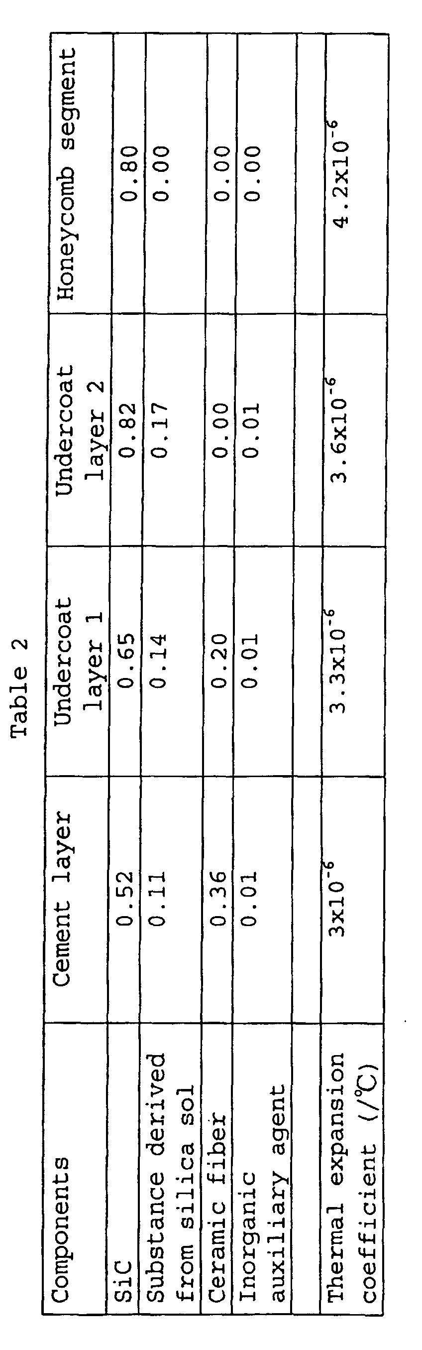
- the bonding layer comprises an undercoat layer formed directly on a side wall of the honeycomb segment, and it is more preferred that a part of the undercoat layer is in pores of the honeycomb segment. It is also preferred that defining a thermal expansion coefficient of the undercoat layer as "Ut”, a thermal expansion coefficient of the honeycomb segment as "Ht” and a thermal expansion coefficient of the cement layer as "At”, a relationship between "Ut", "Ht” and “At” is Ht ⁇ Ut ⁇ At or Ht ⁇ Ut ⁇ At.
- a viscosity of the undercoat agent is low relative to a viscosity of the cement. It is also preferred that both the undercoat agent and the cement contain a solid component and a liquid component, defining a content of at least one component Y constituting the solid component of the cement as "Ay”, a content of the component Y in the honeycomb segment as "Hy” and a content of the component Y in the solid component of the undercoat agent as "Uy”, a relationship between "Ay", "Hy” and “Uy” is Hy ⁇ Uy ⁇ Ay or Hy ⁇ Uy ⁇ Ay.
- the undercoat layer 9 is formed directly on the side wall 7 of the honeycomb segment and it is more preferred that the undercoat layer 9 is formed on both side walls 7 of two honeycomb segments to be bonded with each other.
- the side wall 7 of the honeycomb segment is porous, it is preferred to hold a part of the undercoat layer extending into pores of the side wall 7 because the bond between the honeycomb segment and the undercoat layer becomes stronger owing to a so-called anchor effect.
- each honeycomb segment 12 has, for example, a basic tetragonal prism shape such as shown in Fig. 3 and these basic shapes are bonded into one piece as shown in Figs. 1(a) and 1(b) so that the shapes of the outermost honeycomb segments of a honeycomb structure 1 to be produced are matched to the peripheral shape of the honeycomb structure 1. It is also possible to allow each honeycomb segment 12 to have a fan-shaped section.
- the particulate matter present in the exhaust gas is trapped by the partition walls.
- the engine emitting the exhaust gas receives a higher load, and there appear reductions in fuel consumption and drivability. Therefore, heating by a heater or the like is periodically conducted to burn and remove the particulate matter and regenerate the filter.
- the honeycomb structure may be loaded with the above-mentioned metal having a catalytic activity.
- the honeycomb structure 1 produced according to the present invention is used as a filter, particularly as a DPF or the like, it is preferred that the openings of the through-holes 3 are plugged alternately with a sealant, and it is further preferred that each end face of the structure is plugged so as to have a checkered pattern.
- the plugging with a sealant can be conducted by masking those through-holes not to be plugged, applying a raw material of sealant in a slurry state to each end face of the honeycomb segment, and conducting drying and firing. It is preferred to conduct the plugging in the above-mentioned step of honeycomb segment production, that is, after forming the honeycomb segment but before the firing, because the firing can be completed in one time.
- the honeycomb structure may be loaded with a catalyst.
- the method for loading a catalyst can be one ordinarily used by those skilled in the art, and the catalyst loading can be done, for example, by wash-coating a catalyst slurry and conducting drying and firing. This step may be conducted at any timing after forming the honeycomb segment.
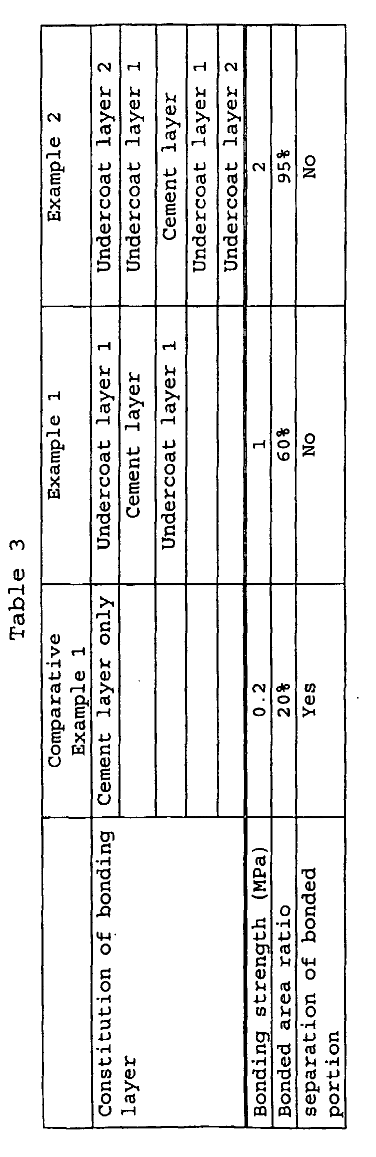
- Each honeycomb structure obtained was observed for separation at the bonded portion.
- Each honeycomb structure was also measured for bonding strength at the bonded portion by a four-point bending test.
- the portion separated at the interface between the bonding layer and the honeycomb segment was taken as no bonding; the portion separated by breakage of bonding layer (the interface being not separated) was taken as bonded area; and the ratio of the bonded area to the total bonding area was taken as bonded area ratio.
Landscapes
- Chemical & Material Sciences (AREA)
- Engineering & Computer Science (AREA)
- Chemical Kinetics & Catalysis (AREA)
- Ceramic Engineering (AREA)
- Organic Chemistry (AREA)
- Materials Engineering (AREA)
- Physics & Mathematics (AREA)
- Structural Engineering (AREA)
- Geometry (AREA)
- Manufacturing & Machinery (AREA)
- Environmental & Geological Engineering (AREA)
- Combustion & Propulsion (AREA)
- Mechanical Engineering (AREA)
- Health & Medical Sciences (AREA)
- General Engineering & Computer Science (AREA)
- Oil, Petroleum & Natural Gas (AREA)
- Biomedical Technology (AREA)
- Analytical Chemistry (AREA)
- General Chemical & Material Sciences (AREA)
- Inorganic Chemistry (AREA)
- Toxicology (AREA)
- Thermal Sciences (AREA)
- Filtering Materials (AREA)
- Catalysts (AREA)
- Filtering Of Dispersed Particles In Gases (AREA)
- Ceramic Products (AREA)
- Exhaust Gas After Treatment (AREA)
- Laminated Bodies (AREA)
Abstract
Description

Claims (10)
- A honeycomb structure comprising a plurality of honeycomb segments bonded into one piece via a bonding layer, each segment having a number of through-holes divided from each other by porous partition walls and extending in an axial direction of the honeycomb segment,
wherein the bonding layer comprises at least one cement layer and at least one undercoat layer present between the honeycomb segment and the cement layer. - A honeycomb structure according to Claim 1, wherein the bonding layer comprises an undercoat layer formed directly on a side wall of the honeycomb segment.
- A honeycomb structure according to Claim 2, wherein a part of the undercoat layer is in pores of the honeycomb segment.
- A honeycomb structure according to any of Claims 1 to 3, wherein defining a thermal expansion coefficient of the undercoat layer as "Ut", a thermal expansion coefficient of the honeycomb segment as "Ht" and a thermal expansion coefficient of the cement layer as "At", a relationship between "Ut", "Ht" and "At" is Ht≧Ut≧At or Ht≦Ut≦At.
- A honeycomb structure according to any of Claims 1 to 4, wherein defining a content of at least one component X constituting the cement layer as "Ax", a content of the component X in the honeycomb segment as "Hx" and a content of the component X in the undercoat layer as "Ux", a relationship between "Ax", "Hx" and "UX" is Hx≦Ux≦Ax or Hx ≧Ux≧Ax.
- A honeycomb structure according to any of Claims 1 to 5, wherein the cement layer and the undercoat layer are made of a cement and an undercoat agent, respectively, and a viscosity of the undercoat agent is low relative to a viscosity of the cement.
- A process for producing a honeycomb structure, comprising steps of:wherein the step of bonding the honeycomb segments comprises:producing honeycomb segments each having a number of through-holes divided from each other by porous partition walls and extending in the axial direction of the honeycomb segment; andbonding the honeycomb segments to produce a honeycomb structure,applying at least one layer of an undercoat agent on the honeycomb segment;applying at least one layer of a cement; andbonding the honeycomb segments into one piece.
- A process for producing a honeycomb structure according to Claim 7, wherein a viscosity of the undercoat agent is low relative to a viscosity of the cement.
- A process for producing a honeycomb structure according to Claim 7 or 8, wherein both the undercoat agent and the cement contain a solid component and a liquid component, defining a content of at least one component Y constituting the solid component of the cement as "Ay", a content of the component Y in the honeycomb segment as "Hy" and a content of the component Y in the solid component of the undercoat agent as "Uy", a relationship between "Ay", "Hy" and "Uy" is Hy≦Uy≦Ay or Hy≧Uy≧Ay.
- A process for producing a honeycomb structure, comprising a step of bonding honeycomb segments to produce a honeycomb structure, each honeycomb segment having a number of through-holes divided from each other by porous partition walls and extending in the axial direction of the honeycomb segment, wherein the step of bonding the honeycomb segments comprises: applying at least one layer of an undercoat agent on each honeycomb segment; applying at least one layer of a cement; and bonding the honeycomb segments into one piece.
Applications Claiming Priority (3)
| Application Number | Priority Date | Filing Date | Title |
|---|---|---|---|
| JP2001372907 | 2001-12-06 | ||
| JP2001372907 | 2001-12-06 | ||
| PCT/JP2002/012696 WO2003048072A1 (en) | 2001-12-06 | 2002-12-04 | Honeycomb structure body and method for manufacturing the same |
Publications (3)
| Publication Number | Publication Date |
|---|---|
| EP1452511A1 true EP1452511A1 (en) | 2004-09-01 |
| EP1452511A4 EP1452511A4 (en) | 2006-05-24 |
| EP1452511B1 EP1452511B1 (en) | 2013-03-13 |
Family
ID=19181715
Family Applications (1)
| Application Number | Title | Priority Date | Filing Date |
|---|---|---|---|
| EP02783763A Expired - Lifetime EP1452511B1 (en) | 2001-12-06 | 2002-12-04 | Method for manufacturing a honeycomb structure body |
Country Status (6)
| Country | Link |
|---|---|
| US (1) | US7138168B2 (en) |
| EP (1) | EP1452511B1 (en) |
| JP (1) | JP4394448B2 (en) |
| AU (1) | AU2002349404A1 (en) |
| PL (1) | PL205740B1 (en) |
| WO (1) | WO2003048072A1 (en) |
Cited By (18)
| Publication number | Priority date | Publication date | Assignee | Title |
|---|---|---|---|---|
| EP1685899A1 (en) * | 2005-02-01 | 2006-08-02 | Ibiden Co., Ltd. | Honeycomb structure body |
| EP1724448A3 (en) * | 2002-02-05 | 2006-12-06 | Ibiden Co., Ltd. | Honeycomb filter for purifyng exhaust gases, adhesive, coating material, and manufacturing method of honeycomb filter for purifying exhaust gases |
| US7309370B2 (en) | 2002-02-05 | 2007-12-18 | Ibiden Co., Ltd. | Honeycomb filter for exhaust gas decontamination |
| WO2008076231A3 (en) * | 2006-12-13 | 2009-02-12 | Peter R Strutt | Electrode assembly for a solid oxide fuel cell and method for making the same |
| WO2010038245A1 (en) * | 2008-09-30 | 2010-04-08 | Pirelli & C. Eco Technology S.P.A. | Honeycomb structural body for exhaust gas purification |
| US7846526B2 (en) | 2004-12-27 | 2010-12-07 | Ibiden Co., Ltd | Honeycomb structural body and sealing material layer |
| US7851041B2 (en) | 2005-06-24 | 2010-12-14 | Ibiden Co., Ltd. | Honeycomb structure |
| US7879429B2 (en) | 2005-06-24 | 2011-02-01 | Ibiden Co., Ltd | Honeycomb structure |
| US7879427B2 (en) | 2005-06-24 | 2011-02-01 | Ibiden Co., Ltd | Honeycomb structure |
| US7879428B2 (en) | 2005-06-24 | 2011-02-01 | Ibiden Co., Ltd | Honeycomb structure |
| US7879430B2 (en) | 2005-06-24 | 2011-02-01 | Ibiden Co., Ltd | Honeycomb structure |
| US7879426B2 (en) | 2005-06-24 | 2011-02-01 | Ibiden Co., Ltd | Honeycomb structure |
| EP1930061A3 (en) * | 2006-12-07 | 2011-03-02 | NGK Insulators, Ltd. | Bonding material composition and method for manufacturing the same, and joined body and method for manufacturing the same |
| US7964263B2 (en) | 2006-03-30 | 2011-06-21 | Ngk Insulators, Ltd. | Bonded element, honeycomb segment bonded element, and honeycomb structure using the same |
| US7981228B2 (en) | 2006-12-25 | 2011-07-19 | Ngk Insulators, Ltd. | Joined body and method for manufacturing the same |
| EP1982767A4 (en) * | 2006-02-10 | 2014-02-05 | Ngk Insulators Ltd | HONEYCOMB SEGMENT, HONEYCOMB STRUCTURE AND METHOD FOR PRODUCING THE SAME |
| CN105986856A (en) * | 2015-03-16 | 2016-10-05 | 日本碍子株式会社 | Honeycomb structure |
| CN105986857A (en) * | 2015-03-16 | 2016-10-05 | 日本碍子株式会社 | Honeycomb structure |
Families Citing this family (28)
| Publication number | Priority date | Publication date | Assignee | Title |
|---|---|---|---|---|
| FR2833857B1 (en) * | 2001-12-20 | 2004-10-15 | Saint Gobain Ct Recherches | FILTER BODY COMPRISING A PLURALITY OF FILTER BLOCKS, IN PARTICULAR FOR A PARTICLE FILTER |
| FR2864577B1 (en) * | 2003-12-24 | 2006-05-05 | Saint Gobain Ct Recherches | FILTRATION STRUCTURE, ESPECIALLY PARTICULATE FILTER FOR EXHAUST GASES OF AN INTERNAL COMBUSTION ENGINE AND REINFORCING MEMBER FOR SUCH A STRUCTURE |
| JP4815108B2 (en) | 2003-12-26 | 2011-11-16 | イビデン株式会社 | Honeycomb structure |
| KR100796471B1 (en) * | 2004-04-30 | 2008-01-21 | 니뽄 가이시 가부시키가이샤 | Honeycomb structure and its manufacturing method |
| CN100453511C (en) * | 2005-03-28 | 2009-01-21 | 揖斐电株式会社 | Honeycomb structure and sealing material |
| WO2006137163A1 (en) * | 2005-06-24 | 2006-12-28 | Ibiden Co., Ltd. | Honeycomb structure body |
| JP5031562B2 (en) * | 2005-06-24 | 2012-09-19 | イビデン株式会社 | Honeycomb structure |
| JP4753781B2 (en) * | 2005-06-24 | 2011-08-24 | イビデン株式会社 | Honeycomb structure |
| JP4753782B2 (en) * | 2005-06-24 | 2011-08-24 | イビデン株式会社 | Honeycomb structure |
| JP2007115350A (en) * | 2005-10-20 | 2007-05-10 | Orion Denki Kk | Reproducing apparatus provided with repeat reproduction function, and repeat reproduction function execution program |
| JP5037809B2 (en) * | 2005-10-25 | 2012-10-03 | 日本碍子株式会社 | Honeycomb structure |
| JP5469305B2 (en) * | 2005-12-14 | 2014-04-16 | 日本碍子株式会社 | Bonding material, manufacturing method thereof, and honeycomb structure using the same |
| WO2007122716A1 (en) * | 2006-04-20 | 2007-11-01 | Ibiden Co., Ltd. | Carrier device and process for producing honeycomb structure |
| KR100818570B1 (en) * | 2006-04-27 | 2008-04-03 | 이비덴 가부시키가이샤 | Honeycomb Structures and Sealants |
| JPWO2008059576A1 (en) | 2006-11-16 | 2010-02-25 | イビデン株式会社 | Honeycomb structure and manufacturing method thereof |
| US20080178992A1 (en) * | 2007-01-31 | 2008-07-31 | Geo2 Technologies, Inc. | Porous Substrate and Method of Fabricating the Same |
| US7567817B2 (en) * | 2007-05-14 | 2009-07-28 | Geo2 Technologies, Inc. | Method and apparatus for an extruded ceramic biosoluble fiber substrate |
| US7781372B2 (en) * | 2007-07-31 | 2010-08-24 | GE02 Technologies, Inc. | Fiber-based ceramic substrate and method of fabricating the same |
| US7855163B2 (en) * | 2007-05-14 | 2010-12-21 | Geo2 Technologies, Inc. | Low coefficient of thermal expansion bonding system for a high porosity ceramic body and methods of manufacture |
| US9828298B2 (en) * | 2007-11-30 | 2017-11-28 | Corning Incorporated | Cement compositions for applying to honeycomb bodies |
| US8124213B2 (en) * | 2008-05-30 | 2012-02-28 | Corning Incorporated | Flow-through sorbent comprising a metal sulfide |
| JP5649964B2 (en) * | 2008-06-25 | 2015-01-07 | 日本碍子株式会社 | Honeycomb structure |
| JP2012215102A (en) * | 2011-03-31 | 2012-11-08 | Kubota Corp | Diesel particulate filter and exhaust emission control device |
| JP2014054792A (en) * | 2012-09-13 | 2014-03-27 | Ngk Insulators Ltd | Method for manufacturing honeycomb structure |
| JP6320798B2 (en) * | 2014-03-04 | 2018-05-09 | 日本碍子株式会社 | Honeycomb structure |
| CN110582339B (en) * | 2016-12-12 | 2022-05-03 | 康明泰克股份有限公司 | SCR catalyst module and corresponding catalyst reactor thereof |
| US11975285B2 (en) | 2018-11-15 | 2024-05-07 | Corning Incorporated | Tilted cell honeycomb body, extrusion die and method of manufacture thereof |
| US11866377B2 (en) * | 2021-04-21 | 2024-01-09 | Honeywell International Inc. | High temperature interfaces for ceramic composites |
Family Cites Families (13)
| Publication number | Priority date | Publication date | Assignee | Title |
|---|---|---|---|---|
| JPS5546338A (en) | 1978-09-28 | 1980-04-01 | Ngk Insulators Ltd | Heat and shock resistant, revolving and heat-regenerating type ceramic heat exchanger body and its manufacturing |
| US4335783A (en) | 1980-11-10 | 1982-06-22 | Corning Glass Works | Method for improving thermal shock resistance of honeycombed structures formed from joined cellular segments |
| JPS60141667A (en) * | 1983-12-28 | 1985-07-26 | 日本碍子株式会社 | Material for ceramic honeycomb structure |
| JPS6126572A (en) * | 1984-07-16 | 1986-02-05 | 株式会社日本自動車部品総合研究所 | Ceramic product and manufacture |
| JP3084081B2 (en) | 1991-04-18 | 2000-09-04 | 東芝タンガロイ株式会社 | Laminated sintered body |
| JP3121497B2 (en) | 1994-07-14 | 2000-12-25 | イビデン株式会社 | Ceramic structure |
| EP1382443B1 (en) * | 1996-01-12 | 2013-04-24 | Ibiden Co., Ltd. | A filter for purifying exhaust gas |
| JP3971027B2 (en) * | 1998-06-25 | 2007-09-05 | イビデン株式会社 | Ceramic structure bonding apparatus and bonding method |
| JP3967034B2 (en) | 1999-03-30 | 2007-08-29 | イビデン株式会社 | Manufacturing method of ceramic filter unit |
| JP2001096116A (en) * | 1999-09-29 | 2001-04-10 | Ibiden Co Ltd | Ceramic filter assembly, honeycomb filter |
| PL220346B1 (en) * | 2001-10-02 | 2015-10-30 | Ngk Insulators Ltd | Honeycomb structural body and method of manufacturing the structural body |
| JP3893049B2 (en) * | 2001-11-20 | 2007-03-14 | 日本碍子株式会社 | Honeycomb structure and manufacturing method thereof |
| JP4067830B2 (en) | 2002-01-24 | 2008-03-26 | 日本碍子株式会社 | Ceramic structure joining apparatus and joining method |
-
2002
- 2002-12-04 JP JP2003549268A patent/JP4394448B2/en not_active Expired - Lifetime
- 2002-12-04 WO PCT/JP2002/012696 patent/WO2003048072A1/en not_active Ceased
- 2002-12-04 EP EP02783763A patent/EP1452511B1/en not_active Expired - Lifetime
- 2002-12-04 US US10/496,837 patent/US7138168B2/en not_active Expired - Lifetime
- 2002-12-04 AU AU2002349404A patent/AU2002349404A1/en not_active Abandoned
- 2002-12-04 PL PL374058A patent/PL205740B1/en unknown
Cited By (27)
| Publication number | Priority date | Publication date | Assignee | Title |
|---|---|---|---|---|
| US8029737B2 (en) | 2002-02-05 | 2011-10-04 | Ibiden Co., Ltd. | Honeycomb filter for exhaust gas decontamination, adhesive, coating material and process for producing honeycomb filter for exhaust gas decontamination |
| EP1724448A3 (en) * | 2002-02-05 | 2006-12-06 | Ibiden Co., Ltd. | Honeycomb filter for purifyng exhaust gases, adhesive, coating material, and manufacturing method of honeycomb filter for purifying exhaust gases |
| US7309370B2 (en) | 2002-02-05 | 2007-12-18 | Ibiden Co., Ltd. | Honeycomb filter for exhaust gas decontamination |
| US8128722B2 (en) | 2002-02-05 | 2012-03-06 | Ibiden Co., Ltd. | Honeycomb filter for purifying exhaust gases, adhesive, coating material, and manufacturing method of honeycomb filter for purifying exhaust gases |
| US7846526B2 (en) | 2004-12-27 | 2010-12-07 | Ibiden Co., Ltd | Honeycomb structural body and sealing material layer |
| EP1685899A1 (en) * | 2005-02-01 | 2006-08-02 | Ibiden Co., Ltd. | Honeycomb structure body |
| US7651754B2 (en) | 2005-02-01 | 2010-01-26 | Ibiden Co., Ltd. | Honeycomb structure |
| US7851041B2 (en) | 2005-06-24 | 2010-12-14 | Ibiden Co., Ltd. | Honeycomb structure |
| US7879429B2 (en) | 2005-06-24 | 2011-02-01 | Ibiden Co., Ltd | Honeycomb structure |
| US7879427B2 (en) | 2005-06-24 | 2011-02-01 | Ibiden Co., Ltd | Honeycomb structure |
| US7879428B2 (en) | 2005-06-24 | 2011-02-01 | Ibiden Co., Ltd | Honeycomb structure |
| US7879430B2 (en) | 2005-06-24 | 2011-02-01 | Ibiden Co., Ltd | Honeycomb structure |
| US7879426B2 (en) | 2005-06-24 | 2011-02-01 | Ibiden Co., Ltd | Honeycomb structure |
| EP1982767A4 (en) * | 2006-02-10 | 2014-02-05 | Ngk Insulators Ltd | HONEYCOMB SEGMENT, HONEYCOMB STRUCTURE AND METHOD FOR PRODUCING THE SAME |
| US7964263B2 (en) | 2006-03-30 | 2011-06-21 | Ngk Insulators, Ltd. | Bonded element, honeycomb segment bonded element, and honeycomb structure using the same |
| US8092624B2 (en) | 2006-12-07 | 2012-01-10 | Ngk Insulators, Ltd. | Bonding material composition and method for manufacturing the same, and joined body and method for manufacturing the same |
| EP1930061A3 (en) * | 2006-12-07 | 2011-03-02 | NGK Insulators, Ltd. | Bonding material composition and method for manufacturing the same, and joined body and method for manufacturing the same |
| US8486585B2 (en) | 2006-12-13 | 2013-07-16 | Peter R. Strutt | Electrode assembly for a solid oxide fuel cell and method for making the same |
| WO2008076231A3 (en) * | 2006-12-13 | 2009-02-12 | Peter R Strutt | Electrode assembly for a solid oxide fuel cell and method for making the same |
| US8173327B2 (en) | 2006-12-13 | 2012-05-08 | Strutt Peter R | Electrode assembly for a solid oxide fuel cell and method for making the same |
| US9172097B2 (en) | 2006-12-13 | 2015-10-27 | NanoCell Systems, Inc. | Method for making electrode assembly for a solid oxide fuel cell |
| US7981228B2 (en) | 2006-12-25 | 2011-07-19 | Ngk Insulators, Ltd. | Joined body and method for manufacturing the same |
| WO2010038245A1 (en) * | 2008-09-30 | 2010-04-08 | Pirelli & C. Eco Technology S.P.A. | Honeycomb structural body for exhaust gas purification |
| US9018130B2 (en) | 2008-09-30 | 2015-04-28 | Pirelli & C. Eco Technology S.P.A. | Honeycomb structural body for exhaust gas purification |
| CN105986856A (en) * | 2015-03-16 | 2016-10-05 | 日本碍子株式会社 | Honeycomb structure |
| CN105986857A (en) * | 2015-03-16 | 2016-10-05 | 日本碍子株式会社 | Honeycomb structure |
| CN105986856B (en) * | 2015-03-16 | 2020-11-03 | 日本碍子株式会社 | Honeycomb structure |
Also Published As
| Publication number | Publication date |
|---|---|
| EP1452511A4 (en) | 2006-05-24 |
| US20050079975A1 (en) | 2005-04-14 |
| PL205740B1 (en) | 2010-05-31 |
| EP1452511B1 (en) | 2013-03-13 |
| AU2002349404A1 (en) | 2003-06-17 |
| JP4394448B2 (en) | 2010-01-06 |
| US7138168B2 (en) | 2006-11-21 |
| JPWO2003048072A1 (en) | 2005-04-14 |
| WO2003048072A1 (en) | 2003-06-12 |
| PL374058A1 (en) | 2005-09-19 |
Similar Documents
| Publication | Publication Date | Title |
|---|---|---|
| US7138168B2 (en) | Honeycomb structure body and method for manufacturing the same | |
| EP1741686B1 (en) | Honeycomb structure and method for producing same | |
| EP2502662B1 (en) | Honeycomb filter and manufacturing method of the same | |
| US7056568B2 (en) | Honeycomb structure and process for production thereof | |
| US6984253B2 (en) | Honeycomb filter | |
| EP1679120B1 (en) | Honeycomb structure and method of producing the same | |
| US7396576B2 (en) | Honeycomb structure | |
| US7384441B2 (en) | Honeycomb filter | |
| EP1586547A1 (en) | Coating material, ceramic honeycomb structure and method for production thereof | |
| EP1435348A1 (en) | Honeycomb structural body and method of manufacturing the structural body | |
| EP2119487A1 (en) | Honeycomb structure and method for manufacturing the same | |
| US7300487B2 (en) | Sealing material, method for sealing honeycomb structure and sealed honeycomb structure | |
| KR100595768B1 (en) | Honeycomb structure and its manufacturing method | |
| KR100607476B1 (en) | Honeycomb structure and method of manufacturing the same |
Legal Events
| Date | Code | Title | Description |
|---|---|---|---|
| PUAI | Public reference made under article 153(3) epc to a published international application that has entered the european phase |
Free format text: ORIGINAL CODE: 0009012 |
|
| 17P | Request for examination filed |
Effective date: 20040614 |
|
| AK | Designated contracting states |
Kind code of ref document: A1 Designated state(s): AT BE BG CH CY CZ DE DK EE ES FI FR GB GR IE IT LI LU MC NL PT SE SI SK TR |
|
| AX | Request for extension of the european patent |
Extension state: AL LT LV MK RO |
|
| A4 | Supplementary search report drawn up and despatched |
Effective date: 20060406 |
|
| 17Q | First examination report despatched |
Effective date: 20070323 |
|
| GRAJ | Information related to disapproval of communication of intention to grant by the applicant or resumption of examination proceedings by the epo deleted |
Free format text: ORIGINAL CODE: EPIDOSDIGR1 |
|
| GRAP | Despatch of communication of intention to grant a patent |
Free format text: ORIGINAL CODE: EPIDOSNIGR1 |
|
| GRAS | Grant fee paid |
Free format text: ORIGINAL CODE: EPIDOSNIGR3 |
|
| GRAA | (expected) grant |
Free format text: ORIGINAL CODE: 0009210 |
|
| AK | Designated contracting states |
Kind code of ref document: B1 Designated state(s): DE FR |
|
| REG | Reference to a national code |
Ref country code: DE Ref legal event code: R096 Ref document number: 60244643 Country of ref document: DE Effective date: 20130508 |
|
| PLBE | No opposition filed within time limit |
Free format text: ORIGINAL CODE: 0009261 |
|
| STAA | Information on the status of an ep patent application or granted ep patent |
Free format text: STATUS: NO OPPOSITION FILED WITHIN TIME LIMIT |
|
| 26N | No opposition filed |
Effective date: 20131216 |
|
| REG | Reference to a national code |
Ref country code: DE Ref legal event code: R097 Ref document number: 60244643 Country of ref document: DE Effective date: 20131216 |
|
| REG | Reference to a national code |
Ref country code: FR Ref legal event code: PLFP Year of fee payment: 14 |
|
| REG | Reference to a national code |
Ref country code: FR Ref legal event code: PLFP Year of fee payment: 15 |
|
| REG | Reference to a national code |
Ref country code: FR Ref legal event code: PLFP Year of fee payment: 16 |
|
| PGFP | Annual fee paid to national office [announced via postgrant information from national office to epo] |
Ref country code: DE Payment date: 20211102 Year of fee payment: 20 Ref country code: FR Payment date: 20211109 Year of fee payment: 20 |
|
| REG | Reference to a national code |
Ref country code: DE Ref legal event code: R071 Ref document number: 60244643 Country of ref document: DE |