EP1452219A1 - Water-soluble organic material condensation apparatus - Google Patents
Water-soluble organic material condensation apparatus Download PDFInfo
- Publication number
- EP1452219A1 EP1452219A1 EP01978832A EP01978832A EP1452219A1 EP 1452219 A1 EP1452219 A1 EP 1452219A1 EP 01978832 A EP01978832 A EP 01978832A EP 01978832 A EP01978832 A EP 01978832A EP 1452219 A1 EP1452219 A1 EP 1452219A1
- Authority
- EP
- European Patent Office
- Prior art keywords
- water
- distillation column
- vapor
- organic material
- soluble organic
- Prior art date
- Legal status (The legal status is an assumption and is not a legal conclusion. Google has not performed a legal analysis and makes no representation as to the accuracy of the status listed.)
- Granted
Links
Images



Classifications
-
- B—PERFORMING OPERATIONS; TRANSPORTING
- B01—PHYSICAL OR CHEMICAL PROCESSES OR APPARATUS IN GENERAL
- B01D—SEPARATION
- B01D61/00—Processes of separation using semi-permeable membranes, e.g. dialysis, osmosis or ultrafiltration; Apparatus, accessories or auxiliary operations specially adapted therefor
- B01D61/36—Pervaporation; Membrane distillation; Liquid permeation
- B01D61/366—Apparatus therefor
-
- B—PERFORMING OPERATIONS; TRANSPORTING
- B01—PHYSICAL OR CHEMICAL PROCESSES OR APPARATUS IN GENERAL
- B01D—SEPARATION
- B01D3/00—Distillation or related exchange processes in which liquids are contacted with gaseous media, e.g. stripping
- B01D3/14—Fractional distillation or use of a fractionation or rectification column
-
- B—PERFORMING OPERATIONS; TRANSPORTING
- B01—PHYSICAL OR CHEMICAL PROCESSES OR APPARATUS IN GENERAL
- B01D—SEPARATION
- B01D3/00—Distillation or related exchange processes in which liquids are contacted with gaseous media, e.g. stripping
- B01D3/14—Fractional distillation or use of a fractionation or rectification column
- B01D3/143—Fractional distillation or use of a fractionation or rectification column by two or more of a fractionation, separation or rectification step
-
- B—PERFORMING OPERATIONS; TRANSPORTING
- B01—PHYSICAL OR CHEMICAL PROCESSES OR APPARATUS IN GENERAL
- B01D—SEPARATION
- B01D3/00—Distillation or related exchange processes in which liquids are contacted with gaseous media, e.g. stripping
- B01D3/14—Fractional distillation or use of a fractionation or rectification column
- B01D3/143—Fractional distillation or use of a fractionation or rectification column by two or more of a fractionation, separation or rectification step
- B01D3/146—Multiple effect distillation
-
- B—PERFORMING OPERATIONS; TRANSPORTING
- B01—PHYSICAL OR CHEMICAL PROCESSES OR APPARATUS IN GENERAL
- B01D—SEPARATION
- B01D3/00—Distillation or related exchange processes in which liquids are contacted with gaseous media, e.g. stripping
- B01D3/14—Fractional distillation or use of a fractionation or rectification column
- B01D3/32—Other features of fractionating columns ; Constructional details of fractionating columns not provided for in groups B01D3/16 - B01D3/30
- B01D3/322—Reboiler specifications
-
- B—PERFORMING OPERATIONS; TRANSPORTING
- B01—PHYSICAL OR CHEMICAL PROCESSES OR APPARATUS IN GENERAL
- B01D—SEPARATION
- B01D53/00—Separation of gases or vapours; Recovering vapours of volatile solvents from gases; Chemical or biological purification of waste gases, e.g. engine exhaust gases, smoke, fumes, flue gases, aerosols
- B01D53/22—Separation of gases or vapours; Recovering vapours of volatile solvents from gases; Chemical or biological purification of waste gases, e.g. engine exhaust gases, smoke, fumes, flue gases, aerosols by diffusion
- B01D53/228—Separation of gases or vapours; Recovering vapours of volatile solvents from gases; Chemical or biological purification of waste gases, e.g. engine exhaust gases, smoke, fumes, flue gases, aerosols by diffusion characterised by specific membranes
-
- B—PERFORMING OPERATIONS; TRANSPORTING
- B01—PHYSICAL OR CHEMICAL PROCESSES OR APPARATUS IN GENERAL
- B01D—SEPARATION
- B01D61/00—Processes of separation using semi-permeable membranes, e.g. dialysis, osmosis or ultrafiltration; Apparatus, accessories or auxiliary operations specially adapted therefor
- B01D61/36—Pervaporation; Membrane distillation; Liquid permeation
- B01D61/362—Pervaporation
-
- B—PERFORMING OPERATIONS; TRANSPORTING
- B01—PHYSICAL OR CHEMICAL PROCESSES OR APPARATUS IN GENERAL
- B01D—SEPARATION
- B01D71/00—Semi-permeable membranes for separation processes or apparatus characterised by the material; Manufacturing processes specially adapted therefor
- B01D71/02—Inorganic material
- B01D71/028—Molecular sieves
- B01D71/0281—Zeolites
-
- Y—GENERAL TAGGING OF NEW TECHNOLOGICAL DEVELOPMENTS; GENERAL TAGGING OF CROSS-SECTIONAL TECHNOLOGIES SPANNING OVER SEVERAL SECTIONS OF THE IPC; TECHNICAL SUBJECTS COVERED BY FORMER USPC CROSS-REFERENCE ART COLLECTIONS [XRACs] AND DIGESTS
- Y10—TECHNICAL SUBJECTS COVERED BY FORMER USPC
- Y10S—TECHNICAL SUBJECTS COVERED BY FORMER USPC CROSS-REFERENCE ART COLLECTIONS [XRACs] AND DIGESTS
- Y10S159/00—Concentrating evaporators
- Y10S159/27—Micropores
-
- Y—GENERAL TAGGING OF NEW TECHNOLOGICAL DEVELOPMENTS; GENERAL TAGGING OF CROSS-SECTIONAL TECHNOLOGIES SPANNING OVER SEVERAL SECTIONS OF THE IPC; TECHNICAL SUBJECTS COVERED BY FORMER USPC CROSS-REFERENCE ART COLLECTIONS [XRACs] AND DIGESTS
- Y10—TECHNICAL SUBJECTS COVERED BY FORMER USPC
- Y10S—TECHNICAL SUBJECTS COVERED BY FORMER USPC CROSS-REFERENCE ART COLLECTIONS [XRACs] AND DIGESTS
- Y10S159/00—Concentrating evaporators
- Y10S159/28—Porous member
-
- Y—GENERAL TAGGING OF NEW TECHNOLOGICAL DEVELOPMENTS; GENERAL TAGGING OF CROSS-SECTIONAL TECHNOLOGIES SPANNING OVER SEVERAL SECTIONS OF THE IPC; TECHNICAL SUBJECTS COVERED BY FORMER USPC CROSS-REFERENCE ART COLLECTIONS [XRACs] AND DIGESTS
- Y10—TECHNICAL SUBJECTS COVERED BY FORMER USPC
- Y10S—TECHNICAL SUBJECTS COVERED BY FORMER USPC CROSS-REFERENCE ART COLLECTIONS [XRACs] AND DIGESTS
- Y10S203/00—Distillation: processes, separatory
- Y10S203/08—Waste heat
Definitions
- the present invention relates to an apparatus for concentrating a water-soluble organic material, particularly, to an apparatus for concentrating a water-soluble organic material, which comprises a distillation column for distilling aqueous solutions of water-soluble organic materials which form azeotropes with water, for instance, alcohols such as ethanol, propanol, etc.
- distillation is conventionally carried out by using such a concentrating apparatus as shown in Fig. 7.
- a liquid containing ethanol feed
- Part of the liquid in the distillation column 1 is sent from the column bottom 1a to a reboiler 2, in which it is heated to generate the vapor, which is returned to the bottom part of the distillation column 1 and goes upward in the column.
- the vapor and the liquid reached an equilibrium are separated upward and downward at each stage of the distillation column 1.
- concentration proceeds through the stages shown in Fig. 8.
- 1, 2, 3, ... and 13, and 2', 3', ... and 8' in the figure represent the ethanol contents in a vapor phase and a liquid phase in the stages (theoretical stages) of the distillation column 1.
- 1, 2, 3, ... represent the composition at each stage in the concentrating section
- 2', 3', ... represent the composition at each stage in the recovering section.
- the feed and the liquid flowing downward from the stage just above are in contact with the vapor coming upward from the stage just below in the feeding section (feed stage), resulting in the compositions of the vapor phase and the liquid phase as shown in 1 in the figure.
- the relation in a vapor-liquid composition between a certain stage and its above and below stages is determined by the amounts of the circulating vapor and liquid, and the amounts of the liquid and the vapor withdrawn from the column bottom 1a and the column top 1b to the outside, which is shown as the operating line in the figure.
- the concentration of ethanol changes from the vapor-liquid composition 1 at the supply stage to the vapor-liquid composition 13 at the column top 1b stepwise between the operating line and the vapor-liquid equilibrium curve.
- the concentration of ethanol decreases to the vapor-liquid composition 8' at the column bottom 1a stepwise between the operating line and the equilibrium curve.
- the operating line shown in Fig. 8 represents a case where with respect to 1 kg mol of ethanol, 6.7 kg mol of a vapor is generated in the reboiler 2, and 5.5 kg ⁇ mol of a vapor is refluxed by the condenser 3, so that 99% of ethanol is recovered from the feed, thereby obtaining ethanol in a concentration of 84 mol % from the column top 1b.
- energy necessary for concentration is 6000 kJ per 1 kg of ethanol.
- the number of stages necessary for the concentrating section in the distillation column 1 is theoretically 13 in the example shown in Fig. 8, the distillation column is actually provided with as many stages as about 3 times, taking stage efficiency into account.
- the operating line becomes close to the vapor-liquid equilibrium line as the vapor-liquid composition nears the azeotropic point of water and ethanol at the column top, necessitating many stages. Accordingly, when it is tried to reduce energy consumption while keeping the vapor-liquid composition at the column top, the operating line becomes further close to the vapor-liquid equilibrium line, resulting in increase in the stages to a practically impossible number.
- the present invention provides, for instance, the following structure to reduce energy consumption in the process of distillation.
- the apparatus for concentrating a water-soluble organic material comprises a distillation column for distilling an aqueous solution of a water-soluble organic material such as alcohols, etc. azeotropic with water, a vapor discharged from the top of the distillation column or the liquid concentrated from this vapor being supplied to a means other than the distillation column having a function of separating it to water and a water-soluble organic material, in which water is separated so that the water-soluble organic material is concentrated more than in a column top vapor in the distillation column, and then recycled to the distillation column.
- a water-soluble organic material such as alcohols, etc.
- the apparatus for concentrating a water-soluble organic material comprises a first distillation column for preliminarily concentrating a low-concentration aqueous solution of a water-soluble organic material which forms azeotrope with water; a second distillation column receiving the preliminarily concentrated liquid as the feed to discharge vapor or a liquid concentrated from this vapor from its column top; and a means other than the second distillation column for separating the vapor received from the second distillation column or the liquid to water and the water-soluble organic material; water being separated from the vapor or the liquid in this means so that the water-soluble organic material is concentrated more than in a column top vapor in the second distillation column, with the vapor or the liquid then recycled to the second distillation column; and the condensation heat of the vapor discharged from the top of the first or second distillation column being used as a heat source for vaporizing a liquid in a bottom of the other distillation column.
- the operation temperature of the distillation column in the above apparatus for concentrating a water-soluble organic material is usually 80°C or higher, for instance, adsorbents usable at high temperatures may be used in the means other than the distillation column. It is preferable, however, to use a zeolite membrane having high heat resistance to separate the water-soluble organic material from water.
- Fig. 1 shows an example of the structure of an apparatus for concentrating a water-soluble organic material according to the present invention
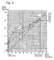
- Fig. 2 shows the process of concentrating ethanol in the distillation column shown in Fig. 1.
- the same parts as in the conventional distillation column shown in Fig. 7 are assigned with the same reference numerals as in Fig. 7, and their explanation will be omitted.
- a vapor-permeable separator (other means than the distillation column) 4 comprising a zeolite membrane for separating a water-soluble organic material (ethanol in this embodiment) from water is disposed in a vapor flow path from the column top 1b of the distillation column 1 to the condenser 3.
- This vapor-permeable separator 4 can separate ethanol and water over their azeotropic point.
- the conventional distillation column fails to increase the percentage of an alcohol in the reflux to the higher extent than the column top vapor, it is possible, as shown in Fig. 2, to concentrate ethanol in a state where the operating line has a small gradient in the concentrating section, namely with small energy consumption, by increasing the percentage of ethanol in the reflux than in the column top vapor.
- the operation shown in Fig. 2 is achieved at an ethanol-recovering ratio of 99% and at an ethanol concentration of 84 mol % as in the case shown in Fig. 8.
- a vapor having an ethanol concentration of 80 mol % is concentrated to 84 mol % in the vapor-permeable separator 4.
- Energy necessary for the concentration is 4400 kJ per 1 kg of ethanol, making it possible to concentrate ethanol with as small energy as 73% in the conventional apparatus shown in Fig. 7.
- the present invention can drastically reduce thermal energy necessary for the concentration of ethanol.
- the necessary number of stages in the concentrating section of the distillation column 1 can be reduced than in the conventional distillation column, by concentrating ethanol near the azeotropic point of water and ethanol in the vapor-permeable separator 4.
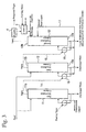
- FIG. 2 A structural example of an apparatus for concentrating a water-soluble organic material, which has been contemplated to meet such necessity, is shown in Fig. 3.
- two first distillation columns 11, 12 are connected in series to a second distillation column 13 provided with a vapor-permeable separator 4, which comprises a zeolite membrane in the vapor flow path from the column top 13b to condenser 3, as in the distillation column 1 shown in Fig. 1.
- the vapor discharged from the tops 11b, 12b of the first-stage distillation columns 11, 12 is supplied to reboiler 16 connected to the bottoms 12a, 13a of the second-stage distillation columns 12, 13 via flow paths 14, 15, so that the vapor is utilized for the heating of the column bottoms 12a, 13a, and cooled and condensed.
- the resultant liquids are merged in a flow path 17, and supplied to the second distillation column 13 as a feed.
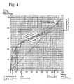
- the process of concentrating ethanol in the second distillation column 13 is shown in Fig. 4.
- the low-concentration ethanol solution is preliminarily concentrated to an ethanol concentration of 20 mol % by the first distillation columns 11, 12.
- the ethanol solution is distilled in the second distillation column 13 according to the same operation as in the above distillation column 1 shown in Fig. 1.
- the second distillation column 13 needs smaller energy, while the first distillation columns 11, 12 need more thermal energy for distillation.
- the amount of heat that should be supplied from outside can be reduced to a level substantially necessary for the heating of the reboiler 16 connected to the second distillation column 13.
- the present invention is not restricted to the above embodiments but includes all applications and modifications unless they deviate from the spirit of the present invention.
- usable as the means other than the distillation column are not only the above-described vapor-permeable separator 4 comprising a zeolite membrane for separating an alcohol from water, but also membrane separators comprising other separation (separating) membranes, adsorption means for separating alcohols from water by the difference in adsorbability to water and alcohols, etc.
- the vapor discharged from the top of the distillation column may be once condensed, so that water is separated from the condensed liquid by a pervaporation separator comprising a zeolite membrane or other membranes, with the separated liquid recycled to the distillation column.
- heating by heat supplied from outside is not necessarily restricted to the first distillation column 11 among those disposed in series.
- one or both of the distillation columns 12, 13 may be heated by an external heat source, and the vapor discharged from these distillation columns 12, 13 may be used to heat the other distillation column (for instance, first distillation column 11).
- Fig. 5 is a view showing the vapor-liquid equilibrium of water and 2-propanol.
- propanol were concentrated by a conventional distillation method, there would be restrictions in an operation with reduced energy consumption, because the operating line is close to the vapor-liquid equilibrium line near the azeotropic point.
- a membrane separator such as the vapor-permeable separator 4 or an adsorption means, etc.
- the zeolite membrane has a function of separating water not only from alcohols but also from other water-soluble organic materials. Accordingly, the present invention is applicable to the concentration of esters, amines, aldehydes, organic acids, etc., which form azeotropes with water.
- the reflux liquid has a concentration equal to or lower than the azeotropic point of water and ethanol in the embodiments shown in Figs. 1 and 3, ethanol in the vapor may be concentrated exceeding the azeotropic point by using the vapor-permeable separator 4 comprising a zeolite membrane. Accordingly, the optimum reflux concentration of the second distillation column 13 may be determined in a wide range including a concentration equal to or higher than the azeotropic point, depending on the concentration of ethanol supplied from the first distillation columns 11, 12 to the second distillation column 13, thereby further reducing energy consumption. This is also an effect obtained by the present invention.
- Fig. 6 shows an example, in which 1000 kg of a 3-mol-% aqueous ethanol solution is supplied to obtain ethanol in a concentration of 85 mol % or more using the apparatus for concentrating a water-soluble organic material according to the present invention.
- the feed is preheated to a predetermined temperature by preheaters 5, and then supplied to the first distillation columns 11, 12, respectively, through which it was concentrated to 20 mol %.
- the first distillation columns 11 and 12 are operated at 520 kPa and 220 kPa, respectively.
- the reboiler 21 connected to the first distillation column 11 is heated by steam at 700 kPa charged from outside, and the reboiler 22 connected to the first distillation column 12 is heated by the condensation heat of the vapor discharged from the top 11b of the first distillation column 11.
- the vapor discharged from the top of the first distillation column 12 is used for the heating of the reboiler 23 connected to the second distillation column 13 operated at the atmospheric pressure. Because there is some excess heat, part of the vapor is cooled and condensed by an auxiliary condenser 6. In the case of obtaining a 20-mol-% solution from a 3-mol-% solution, refluxing is unnecessary in the first distillation columns 11, 12.
- a 20-mol-% aqueous ethanol solution supplied from the first distillation columns 11, 12 is supplied to the second distillation column 13, and a vapor containing ethanol in a concentration of 80 mol % is withdrawn from the top 13b of the second distillation column 13.
- This vapor is caused to pass through the vapor-permeable separator 4 comprising a zeolite A membrane available from Mitsui Engineering & Shipbuilding Co., Ltd. to concentrate ethanol to a concentration of 85 mol %.
- Part of the vapor, in which ethanol is concentrated is withdrawn outside the system as a product, while the other part of the vapor is condensed by the condenser 3 and then recycled to the second distillation column 13.
- a liquid containing ethanol in a concentration of 3 mol % is withdrawn from the bottom 13a of the second distillation column 13 and recycled to the first distillation columns 11, 12 on the supply side. Because a water vapor passing through the zeolite membrane of the vapor-permeable separator 4 contains a small percentage of ethanol, it is cooled and condensed by the condenser 7, and then recycled to the first distillation columns 11, 12 on the supply side.
- Table 1 shows the flow rates and ethanol concentrations of the liquid in main parts of the apparatus shown in Fig. 6 for concentrating a water-soluble organic material.
- Parts A B C D E F Feed Feed Distilled Vapor Recycled Liquid Discharged Water Heating Vapor Flow Rate (kg/h) 1000.0 218.5 78.4 140.1 921.6 110 Concentration of Ethanol mol %) 3.0 20.0 85.0 3.0 100 ppm by weight -
- a final product is a so-called anhydrous alcohol of 99.5 mol %. Accordingly, part of the vapor passing through the vapor-permeable separator 4, which contains ethanol in a concentration of 85 mol %, is withdrawn outside the system, and the remaining vapor is condensed and recycled to the second distillation column 13. The vapor distillate is further concentrated by the zeolite membrane to obtain an anhydrous alcohol. However, in the case of obtaining 85 mol % (95.7% by volume) of ethanol as a product, the entire vapor may be condensed to withdraw part of the condensed liquid as a product, while recycling the remainder to the distillation column.
Landscapes
- Chemical & Material Sciences (AREA)
- Chemical Kinetics & Catalysis (AREA)
- Engineering & Computer Science (AREA)
- Water Supply & Treatment (AREA)
- General Chemical & Material Sciences (AREA)
- Inorganic Chemistry (AREA)
- Geology (AREA)
- Analytical Chemistry (AREA)
- Life Sciences & Earth Sciences (AREA)
- Oil, Petroleum & Natural Gas (AREA)
- Vaporization, Distillation, Condensation, Sublimation, And Cold Traps (AREA)
- Separation Using Semi-Permeable Membranes (AREA)
- Organic Low-Molecular-Weight Compounds And Preparation Thereof (AREA)
- Heat Treatment Of Water, Waste Water Or Sewage (AREA)
- Addition Polymer Or Copolymer, Post-Treatments, Or Chemical Modifications (AREA)
- Colloid Chemistry (AREA)
- Paper (AREA)
Abstract
Description
| Parts | A | B | C | D | E | F |
| Feed | Feed | Distilled Vapor | Recycled Liquid | Discharged Water | Heating Vapor | |
| Flow Rate (kg/h) | 1000.0 | 218.5 | 78.4 | 140.1 | 921.6 | 110 |
| Concentration of Ethanol mol %) | 3.0 | 20.0 | 85.0 | 3.0 | 100 ppm by weight | - |
Claims (6)
- An apparatus for concentrating a water-soluble organic material comprising a distillation column for distilling an aqueous solution of a water-soluble organic material azeotropic with water, a vapor discharged from a top of said distillation column or a liquid concentrated from this vapor being supplied to a means other than said distillation column having a function of separating it to water and a water-soluble organic material, in which water is separated so that said water-soluble organic material is concentrated more than in a column top vapor in said distillation column, and then refluxed to said distillation column.
- The apparatus for concentrating a water-soluble organic material according to claim 1, wherein said means other than said distillation column comprises a separating membrane for separating said water-soluble organic material from water.
- The apparatus for concentrating a water-soluble organic material according to claim 2, wherein said separating membrane is a zeolite membrane.
- An apparatus for concentrating a water-soluble organic material comprising a first distillation column for preliminarily concentrating an aqueous solution of a water-soluble organic material azeotropic with water; a second distillation column receiving a preliminarily concentrated liquid as a feed to discharge a vapor or a liquid concentrated from this vapor from its column top; and a means other than said second distillation column for separating said vapor received from said second distillation column or said liquid to water and said water-soluble organic material; wherein water is separated from said vapor or said liquid in said means so that said water-soluble organic material is concentrated more than in a column top vapor in said second distillation column, with said vapor or said liquid then refluxed to said second distillation column; and wherein the condensation heat of said vapor discharged from said top of said first or second distillation column is used as a heat source for vaporizing a liquid in a bottom of another distillation column.
- The apparatus for concentrating a water-soluble organic material according to claim 4, wherein said means other than said distillation column comprises a separating membrane for separating said water-soluble organic material from water.
- The apparatus for concentrating a water-soluble organic material according to claim 5, wherein said separating membrane is a zeolite membrane.
Applications Claiming Priority (1)
| Application Number | Priority Date | Filing Date | Title |
|---|---|---|---|
| PCT/JP2001/009186 WO2003035222A1 (en) | 2001-10-19 | 2001-10-19 | Water-soluble organic material condensation apparatus |
Publications (3)
| Publication Number | Publication Date |
|---|---|
| EP1452219A1 true EP1452219A1 (en) | 2004-09-01 |
| EP1452219A4 EP1452219A4 (en) | 2006-03-22 |
| EP1452219B1 EP1452219B1 (en) | 2010-02-10 |
Family
ID=11737847
Family Applications (1)
| Application Number | Title | Priority Date | Filing Date |
|---|---|---|---|
| EP01978832A Expired - Lifetime EP1452219B1 (en) | 2001-10-19 | 2001-10-19 | Water-soluble organic material distillation apparatus |
Country Status (7)
| Country | Link |
|---|---|
| US (1) | US7699961B2 (en) |
| EP (1) | EP1452219B1 (en) |
| JP (1) | JP4831934B2 (en) |
| AT (1) | ATE457192T1 (en) |
| DE (1) | DE60141303D1 (en) |
| ES (1) | ES2339223T3 (en) |
| WO (1) | WO2003035222A1 (en) |
Cited By (6)
| Publication number | Priority date | Publication date | Assignee | Title |
|---|---|---|---|---|
| WO2007095706A1 (en) * | 2006-02-24 | 2007-08-30 | Siemens Ltda. | Process and system for producing alcohol by split-feed distillation |
| WO2007095875A1 (en) * | 2005-04-20 | 2007-08-30 | White Fox Technologies Limited | Separation method |
| WO2007146094A2 (en) | 2006-06-08 | 2007-12-21 | Yale University | Multi stage column distillation (mscd) method for osmotic solute recovery |
| WO2008046626A3 (en) * | 2006-10-18 | 2008-08-14 | Gea Wiegand Gmbh | Installation for the distillation of drinking alcohol, especially whiskey |
| WO2017058851A1 (en) * | 2015-09-30 | 2017-04-06 | Dow Global Technologies Llc | Process for hybrid distillation and membrane separation of organic components from water in making eha (ethylhexyl-acrylate) |
| EP3195915A1 (en) * | 2016-01-20 | 2017-07-26 | Sulzer Chemtech AG | A system for the purification of an organic solvent and a process for the use thereof |
Families Citing this family (17)
| Publication number | Priority date | Publication date | Assignee | Title |
|---|---|---|---|---|
| KR100654271B1 (en) | 2003-02-21 | 2006-12-08 | 가부시키가이샤 붓산 나노테크 겐큐쇼 | Method for concentrating water-soluble organic material |
| JP4427572B2 (en) * | 2007-03-15 | 2010-03-10 | 三菱重工業株式会社 | Dehydrator |
| JP4898502B2 (en) * | 2007-03-15 | 2012-03-14 | 三菱重工業株式会社 | Fluid transport method |
| JP2008221176A (en) * | 2007-03-15 | 2008-09-25 | Mitsubishi Heavy Ind Ltd | Dewatering system and dewatering method |
| EP2251075B1 (en) | 2008-03-14 | 2013-12-25 | Mitsubishi Heavy Industries, Ltd. | Dehydration method |
| US8137565B2 (en) * | 2009-05-27 | 2012-03-20 | Conocophillips Company | Naphthenic acid removal and conversion |
| EA027334B1 (en) | 2009-10-28 | 2017-07-31 | Оасис Уотер, Инк. | Forward osmosis separation processes |
| US9044711B2 (en) | 2009-10-28 | 2015-06-02 | Oasys Water, Inc. | Osmotically driven membrane processes and systems and methods for draw solute recovery |
| US8500848B2 (en) * | 2010-11-12 | 2013-08-06 | The Texas A&M University System | Systems and methods for air dehumidification and cooling with membrane water vapor rejection |
| US10486079B1 (en) | 2016-01-08 | 2019-11-26 | Whitefox Technologies Limited | Process and system for dehydrating a byproduct stream in ethanol production |
| US10729987B1 (en) | 2016-12-09 | 2020-08-04 | Whitefox Technologies Limited | Process and system for heat integration in ethanol production |
| US10874956B2 (en) | 2018-05-07 | 2020-12-29 | Whitefox Technologies Limited | Process and system for dehydrating a product stream in ethanol production |
| US10881979B2 (en) * | 2018-08-30 | 2021-01-05 | Nnb Nutrition Usa Llc | Device for multistage continuous preparation of deuterium depleted water |
| CN109771981B (en) * | 2019-02-02 | 2021-05-18 | 南京工业大学 | Energy-saving rectification-membrane method-rectification coupling separation method for azeotropic organic solvent |
| JP2024065124A (en) * | 2021-03-11 | 2024-05-15 | 三菱ケミカル株式会社 | Method and apparatus for separating water-soluble compounds |
| EP4415844A1 (en) | 2021-10-15 | 2024-08-21 | Whitefox Technologies Limited | Heat integrated process and system for organic solvent production using vapor recompression |
| KR102910267B1 (en) * | 2022-12-09 | 2026-01-09 | 한국건설기술연구원 | Fractional_submerged membrane distillation crystallizer (f-smdc) for treatment of high salinity solution, and operating method for the same |
Family Cites Families (29)
| Publication number | Priority date | Publication date | Assignee | Title |
|---|---|---|---|---|
| JPS339766B1 (en) * | 1956-01-17 | 1958-11-12 | ||
| FR1399653A (en) * | 1964-04-06 | 1965-05-21 | Melle Usines Sa | Continuous process for the preparation of functional alcohol derivatives |
| DE2340566C2 (en) * | 1973-08-10 | 1985-11-07 | Peter, Siegfried, Prof.Dr., 8520 Erlangen | Process for the separation of components from mixtures of substances with low vapor pressure with the aid of a compressed gas under supercritical conditions and another substance that influences the separation effect |
| DE3037736C2 (en) * | 1980-10-06 | 1984-01-26 | Achim Dipl.-Ing. 6650 Homburg Ballweg | Process for the dewatering of mixtures of organic liquids and water |
| JPS5791702A (en) | 1980-12-01 | 1982-06-08 | Toray Ind Inc | Distillation device |
| JPS57209602A (en) * | 1981-06-22 | 1982-12-23 | Hidemasa Tsuruta | Vapor re-compression type distillation |
| JPS6042210B2 (en) | 1981-07-29 | 1985-09-20 | 昭和電工株式会社 | Method for producing anhydrous ethanol |
| JPS58211000A (en) * | 1982-06-03 | 1983-12-08 | 株式会社トクヤマ | Organic solvent purification |
| US4472246A (en) * | 1982-08-20 | 1984-09-18 | Ashland Oil, Inc. | Process for recovery of amine from spent acid stripping liquor |
| JPS61158774A (en) | 1984-12-29 | 1986-07-18 | Tokyo Electric Power Co Inc:The | Device for purifying ethanol |
| DE3610011A1 (en) * | 1986-03-25 | 1987-10-08 | Geesthacht Gkss Forschung | METHOD FOR SEPARATING THE COMPONENTS OF A LIQUID MIXTURE |
| JPS63254987A (en) | 1987-04-13 | 1988-10-21 | Ube Ind Ltd | Dehydration and concentration of alcoholic fermentation liquor |
| JPS63278522A (en) | 1987-05-08 | 1988-11-16 | Ube Ind Ltd | Separation of volatile mixture |
| DE3723193A1 (en) * | 1987-07-14 | 1989-01-26 | Metallgesellschaft Ag | METHOD FOR PRODUCING ALCOHOLATES |
| NL8702150A (en) * | 1987-09-09 | 1989-04-03 | Tno | METHOD AND MEMBRANE FOR REMOVING WATER VAPOR BY VAPOR PERMEATION FROM A GAS-VAPOR MIXTURE. |
| JPH035431A (en) | 1989-06-02 | 1991-01-11 | Tsusho Sangiyoushiyou Kiso Sangiyoukiyokuchiyou | Method for dehydrating alcohol with propylene |
| DE4019170A1 (en) * | 1990-06-15 | 1991-12-19 | Henkel Kgaa | METHOD FOR CARRYING OUT A BALANCE REACTION USING DAMPER PERMEATION |
| JPH0463110A (en) * | 1990-07-03 | 1992-02-28 | Ube Ind Ltd | Separation purification method of alcohol-containing reaction liquid |
| JP2854458B2 (en) * | 1992-04-30 | 1999-02-03 | 東洋エンジニアリング株式会社 | Pressure control method for multiple effect distillation apparatus |
| JPH06226002A (en) | 1993-02-03 | 1994-08-16 | Sumitomo Heavy Ind Ltd | Azeotrope separator |
| JPH06277402A (en) * | 1993-03-24 | 1994-10-04 | Sumitomo Heavy Ind Ltd | Method for separating azeotropic mixture and separation device therefor |
| JPH06287153A (en) | 1993-04-02 | 1994-10-11 | Mitsubishi Petrochem Co Ltd | Method for producing absolute ethanol |
| JP3537909B2 (en) * | 1995-03-23 | 2004-06-14 | 三井造船株式会社 | Method for producing ZSM-5 type zeolite membrane and liquid mixture separation membrane |
| ES2158419T3 (en) * | 1996-10-14 | 2001-09-01 | Bayer Ag | PROCEDURE FOR OBTAINING ESTERS OR ALCOHOLATES WITH WATER SEPARATION. |
| DE19732291A1 (en) * | 1997-07-26 | 1999-01-28 | Basf Ag | Process for the separation of trioxane |
| JP3670852B2 (en) * | 1998-07-27 | 2005-07-13 | 三井造船株式会社 | Production method of mixture separation membrane |
| EP0992484A1 (en) * | 1998-10-01 | 2000-04-12 | Kvaerner Process Technology Limited | Process |
| US7291250B1 (en) * | 1999-10-20 | 2007-11-06 | Bionorica Ag | Vacuum distillation system and use thereof for concentrating organic-aqueous solvent mixtures |
| US6755975B2 (en) * | 2002-06-12 | 2004-06-29 | Membrane Technology And Research, Inc. | Separation process using pervaporation and dephlegmation |
-
2001
- 2001-10-19 AT AT01978832T patent/ATE457192T1/en not_active IP Right Cessation
- 2001-10-19 ES ES01978832T patent/ES2339223T3/en not_active Expired - Lifetime
- 2001-10-19 WO PCT/JP2001/009186 patent/WO2003035222A1/en not_active Ceased
- 2001-10-19 JP JP2003537781A patent/JP4831934B2/en not_active Expired - Fee Related
- 2001-10-19 US US10/492,792 patent/US7699961B2/en not_active Expired - Lifetime
- 2001-10-19 DE DE60141303T patent/DE60141303D1/en not_active Expired - Lifetime
- 2001-10-19 EP EP01978832A patent/EP1452219B1/en not_active Expired - Lifetime
Cited By (14)
| Publication number | Priority date | Publication date | Assignee | Title |
|---|---|---|---|---|
| WO2007095875A1 (en) * | 2005-04-20 | 2007-08-30 | White Fox Technologies Limited | Separation method |
| WO2007095706A1 (en) * | 2006-02-24 | 2007-08-30 | Siemens Ltda. | Process and system for producing alcohol by split-feed distillation |
| US8287698B2 (en) | 2006-02-24 | 2012-10-16 | Siemens Ltda. | Process and system for producing alcohol by split-feed distillation |
| US8246791B2 (en) | 2006-06-08 | 2012-08-21 | Yale University | Multi-stage column distillation (MSCD) method for osmotic solute recovery |
| WO2007146094A2 (en) | 2006-06-08 | 2007-12-21 | Yale University | Multi stage column distillation (mscd) method for osmotic solute recovery |
| KR101415627B1 (en) * | 2006-06-08 | 2014-07-11 | 예일 유니버시티 | Multistage Column Distillation (MSCD) Method for Osmotic Solute Recovery |
| EP2035333A4 (en) * | 2006-06-08 | 2011-01-05 | Univ Yale Inc | Multi stage column distillation (mscd) method for osmotic solute recovery |
| AU2007258574B2 (en) * | 2006-06-08 | 2012-02-02 | Yale University | Multi stage column distillation (MSCD) method for osmotic solute recovery |
| WO2008046626A3 (en) * | 2006-10-18 | 2008-08-14 | Gea Wiegand Gmbh | Installation for the distillation of drinking alcohol, especially whiskey |
| GB2457186B (en) * | 2006-10-18 | 2011-04-27 | Grant William & Sons Ltd | Installation for the distillation of drinking alcohol,especially whiskey |
| GB2457186A (en) * | 2006-10-18 | 2009-08-12 | Grant William & Sons Ltd | Installation for the distillation of drinking alcohol,especially whiskey |
| WO2017058851A1 (en) * | 2015-09-30 | 2017-04-06 | Dow Global Technologies Llc | Process for hybrid distillation and membrane separation of organic components from water in making eha (ethylhexyl-acrylate) |
| EP3195915A1 (en) * | 2016-01-20 | 2017-07-26 | Sulzer Chemtech AG | A system for the purification of an organic solvent and a process for the use thereof |
| WO2017125308A1 (en) * | 2016-01-20 | 2017-07-27 | Sulzer Chemtech Ag | A system for the purification of an organic solvent and a process for the use thereof |
Also Published As
| Publication number | Publication date |
|---|---|
| DE60141303D1 (en) | 2010-03-25 |
| US20040256212A1 (en) | 2004-12-23 |
| US7699961B2 (en) | 2010-04-20 |
| ATE457192T1 (en) | 2010-02-15 |
| JPWO2003035222A1 (en) | 2005-02-10 |
| EP1452219A4 (en) | 2006-03-22 |
| JP4831934B2 (en) | 2011-12-07 |
| ES2339223T3 (en) | 2010-05-18 |
| WO2003035222A1 (en) | 2003-05-01 |
| EP1452219B1 (en) | 2010-02-10 |
Similar Documents
| Publication | Publication Date | Title |
|---|---|---|
| US7699961B2 (en) | Apparatus for concentrating water-soluble organic material | |
| KR100654271B1 (en) | Method for concentrating water-soluble organic material | |
| US9266803B2 (en) | Liquid separation by membrane assisted vapor stripping process | |
| JP5369765B2 (en) | Method for purifying fermentation alcohol | |
| US8071798B2 (en) | Production of ethylene oxide | |
| CN104203909B (en) | Purification method of acetonitrile | |
| US7157610B2 (en) | Process for recovering methanol | |
| US20160082363A1 (en) | PURIFICATION DEVICE AND PURIFICATION METHOD USING THE SAME (As Amended) | |
| JP2009263356A (en) | Method for purification-treating fermentation alcohol | |
| US4645569A (en) | Process for producing anhydrous ethanol | |
| WO2014185269A1 (en) | Method for condensing water-soluble organic matter and device for condensing water-soluble organic matter | |
| JPH0463110A (en) | Separation purification method of alcohol-containing reaction liquid | |
| JPH074486B2 (en) | Separation method for multi-component streams | |
| US6884324B2 (en) | Column for concentrating phthalic anhydride | |
| JPH1057704A (en) | Distillation method and distillation apparatus | |
| JP2005177535A (en) | Method and apparatus for concentrating water-soluble organic substances | |
| JP2011218321A (en) | Apparatus and method for distilling volatile organic compound | |
| JPH0521611B2 (en) | ||
| CN101084176B (en) | Method for the recovery of methanol | |
| Brüschke et al. | Economics of industrial pervaporation processes | |
| JPH02253802A (en) | Method for saving heat quantity by combination of distillation and membrane separation in dehydrating separation of aqueous low-boiling-point solvent solution | |
| JPH06145083A (en) | Production of dehydrated ethanol | |
| KR100581707B1 (en) | Method for distilling a mixture of substances and device for realising the same | |
| RU2785430C2 (en) | Methods for production of ethylene oxide and ethylene glycol | |
| JP2002045604A (en) | Distillation apparatus and distillation method using the same |
Legal Events
| Date | Code | Title | Description |
|---|---|---|---|
| PUAI | Public reference made under article 153(3) epc to a published international application that has entered the european phase |
Free format text: ORIGINAL CODE: 0009012 |
|
| 17P | Request for examination filed |
Effective date: 20040513 |
|
| AK | Designated contracting states |
Kind code of ref document: A1 Designated state(s): AT BE CH CY DE DK ES FI FR GB GR IE IT LI LU MC NL PT SE TR |
|
| AX | Request for extension of the european patent |
Extension state: AL LT LV MK RO SI |
|
| RAP1 | Party data changed (applicant data changed or rights of an application transferred) |
Owner name: BUSSAN NANOTECH RESEARCH INSTITUTE, INC. |
|
| A4 | Supplementary search report drawn up and despatched |
Effective date: 20060208 |
|
| RIC1 | Information provided on ipc code assigned before grant |
Ipc: B01D 3/00 20060101ALI20060202BHEP Ipc: B01D 61/36 20060101ALI20060202BHEP Ipc: B01D 71/02 20060101ALI20060202BHEP Ipc: B01D 53/22 20060101AFI20030508BHEP Ipc: B01D 3/36 20060101ALI20060202BHEP Ipc: C07C 7/144 20060101ALI20060202BHEP |
|
| 17Q | First examination report despatched |
Effective date: 20070705 |
|
| RAP1 | Party data changed (applicant data changed or rights of an application transferred) |
Owner name: MITSUBISHI CHEMICAL CORPORATION |
|
| GRAP | Despatch of communication of intention to grant a patent |
Free format text: ORIGINAL CODE: EPIDOSNIGR1 |
|
| RTI1 | Title (correction) |
Free format text: WATER-SOLUBLE ORGANIC MATERIAL DISTILLATION APPARATUS |
|
| GRAS | Grant fee paid |
Free format text: ORIGINAL CODE: EPIDOSNIGR3 |
|
| GRAA | (expected) grant |
Free format text: ORIGINAL CODE: 0009210 |
|
| AK | Designated contracting states |
Kind code of ref document: B1 Designated state(s): AT BE CH CY DE DK ES FI FR GB GR IE IT LI LU MC NL PT SE TR |
|
| REG | Reference to a national code |
Ref country code: GB Ref legal event code: FG4D |
|
| REG | Reference to a national code |
Ref country code: CH Ref legal event code: EP |
|
| REG | Reference to a national code |
Ref country code: IE Ref legal event code: FG4D |
|
| REF | Corresponds to: |
Ref document number: 60141303 Country of ref document: DE Date of ref document: 20100325 Kind code of ref document: P |
|
| REG | Reference to a national code |
Ref country code: NL Ref legal event code: T3 |
|
| REG | Reference to a national code |
Ref country code: ES Ref legal event code: FG2A Ref document number: 2339223 Country of ref document: ES Kind code of ref document: T3 |
|
| PG25 | Lapsed in a contracting state [announced via postgrant information from national office to epo] |
Ref country code: PT Free format text: LAPSE BECAUSE OF FAILURE TO SUBMIT A TRANSLATION OF THE DESCRIPTION OR TO PAY THE FEE WITHIN THE PRESCRIBED TIME-LIMIT Effective date: 20100611 |
|
| PG25 | Lapsed in a contracting state [announced via postgrant information from national office to epo] |
Ref country code: AT Free format text: LAPSE BECAUSE OF FAILURE TO SUBMIT A TRANSLATION OF THE DESCRIPTION OR TO PAY THE FEE WITHIN THE PRESCRIBED TIME-LIMIT Effective date: 20100210 Ref country code: FI Free format text: LAPSE BECAUSE OF FAILURE TO SUBMIT A TRANSLATION OF THE DESCRIPTION OR TO PAY THE FEE WITHIN THE PRESCRIBED TIME-LIMIT Effective date: 20100210 |
|
| PG25 | Lapsed in a contracting state [announced via postgrant information from national office to epo] |
Ref country code: SE Free format text: LAPSE BECAUSE OF FAILURE TO SUBMIT A TRANSLATION OF THE DESCRIPTION OR TO PAY THE FEE WITHIN THE PRESCRIBED TIME-LIMIT Effective date: 20100210 Ref country code: CY Free format text: LAPSE BECAUSE OF FAILURE TO SUBMIT A TRANSLATION OF THE DESCRIPTION OR TO PAY THE FEE WITHIN THE PRESCRIBED TIME-LIMIT Effective date: 20100210 Ref country code: BE Free format text: LAPSE BECAUSE OF FAILURE TO SUBMIT A TRANSLATION OF THE DESCRIPTION OR TO PAY THE FEE WITHIN THE PRESCRIBED TIME-LIMIT Effective date: 20100210 Ref country code: GR Free format text: LAPSE BECAUSE OF FAILURE TO SUBMIT A TRANSLATION OF THE DESCRIPTION OR TO PAY THE FEE WITHIN THE PRESCRIBED TIME-LIMIT Effective date: 20100511 |
|
| PLBE | No opposition filed within time limit |
Free format text: ORIGINAL CODE: 0009261 |
|
| STAA | Information on the status of an ep patent application or granted ep patent |
Free format text: STATUS: NO OPPOSITION FILED WITHIN TIME LIMIT |
|
| 26N | No opposition filed |
Effective date: 20101111 |
|
| PG25 | Lapsed in a contracting state [announced via postgrant information from national office to epo] |
Ref country code: DK Free format text: LAPSE BECAUSE OF FAILURE TO SUBMIT A TRANSLATION OF THE DESCRIPTION OR TO PAY THE FEE WITHIN THE PRESCRIBED TIME-LIMIT Effective date: 20100210 |
|
| PG25 | Lapsed in a contracting state [announced via postgrant information from national office to epo] |
Ref country code: IT Free format text: LAPSE BECAUSE OF FAILURE TO SUBMIT A TRANSLATION OF THE DESCRIPTION OR TO PAY THE FEE WITHIN THE PRESCRIBED TIME-LIMIT Effective date: 20100210 |
|
| PG25 | Lapsed in a contracting state [announced via postgrant information from national office to epo] |
Ref country code: MC Free format text: LAPSE BECAUSE OF NON-PAYMENT OF DUE FEES Effective date: 20101031 |
|
| REG | Reference to a national code |
Ref country code: CH Ref legal event code: PL |
|
| GBPC | Gb: european patent ceased through non-payment of renewal fee |
Effective date: 20101019 |
|
| PG25 | Lapsed in a contracting state [announced via postgrant information from national office to epo] |
Ref country code: LI Free format text: LAPSE BECAUSE OF NON-PAYMENT OF DUE FEES Effective date: 20101031 Ref country code: FR Free format text: LAPSE BECAUSE OF NON-PAYMENT OF DUE FEES Effective date: 20101102 Ref country code: CH Free format text: LAPSE BECAUSE OF NON-PAYMENT OF DUE FEES Effective date: 20101031 |
|
| REG | Reference to a national code |
Ref country code: FR Ref legal event code: ST Effective date: 20110630 |
|
| PG25 | Lapsed in a contracting state [announced via postgrant information from national office to epo] |
Ref country code: GB Free format text: LAPSE BECAUSE OF NON-PAYMENT OF DUE FEES Effective date: 20101019 |
|
| PG25 | Lapsed in a contracting state [announced via postgrant information from national office to epo] |
Ref country code: IE Free format text: LAPSE BECAUSE OF NON-PAYMENT OF DUE FEES Effective date: 20101019 |
|
| PG25 | Lapsed in a contracting state [announced via postgrant information from national office to epo] |
Ref country code: LU Free format text: LAPSE BECAUSE OF NON-PAYMENT OF DUE FEES Effective date: 20101019 |
|
| PG25 | Lapsed in a contracting state [announced via postgrant information from national office to epo] |
Ref country code: TR Free format text: LAPSE BECAUSE OF FAILURE TO SUBMIT A TRANSLATION OF THE DESCRIPTION OR TO PAY THE FEE WITHIN THE PRESCRIBED TIME-LIMIT Effective date: 20100210 |
|
| REG | Reference to a national code |
Ref country code: DE Ref legal event code: R082 Ref document number: 60141303 Country of ref document: DE Representative=s name: STREHL SCHUEBEL-HOPF & PARTNER MBB PATENTANWAE, DE Ref country code: DE Ref legal event code: R081 Ref document number: 60141303 Country of ref document: DE Owner name: MITSUBISHI CHEMICAL CORPORATION, JP Free format text: FORMER OWNER: MITSUBISHI CHEMICAL CORP., TOKIO/TOKYO, JP |
|
| REG | Reference to a national code |
Ref country code: DE Ref legal event code: R082 Ref document number: 60141303 Country of ref document: DE Representative=s name: STREHL SCHUEBEL-HOPF & PARTNER MBB PATENTANWAE, DE Ref country code: DE Ref legal event code: R081 Ref document number: 60141303 Country of ref document: DE Owner name: MITSUBISHI CHEMICAL CORPORATION, JP Free format text: FORMER OWNER: MITSUBISHI RAYON CO., LTD., TOKIO/TOKYO, JP |
|
| REG | Reference to a national code |
Ref country code: ES Ref legal event code: PC2A Owner name: MITSUBISHI CHEMICAL CORPORATION Effective date: 20180130 |
|
| REG | Reference to a national code |
Ref country code: NL Ref legal event code: HC Owner name: MITSUBISHI CHEMICAL CORPORATION; JP Free format text: DETAILS ASSIGNMENT: CHANGE OF OWNER(S), CHANGE OF OWNER(S) NAME; FORMER OWNER NAME: MITSUBISHI RAYON CO., LTD. Effective date: 20180326 Ref country code: NL Ref legal event code: PD Owner name: MITSUBISHI RAYON CO., LTD.; JP Free format text: DETAILS ASSIGNMENT: CHANGE OF OWNER(S), MERGE; FORMER OWNER NAME: MITSUBISHI CHEMICAL CORPORATION Effective date: 20180326 |
|
| PGFP | Annual fee paid to national office [announced via postgrant information from national office to epo] |
Ref country code: NL Payment date: 20200915 Year of fee payment: 20 |
|
| PGFP | Annual fee paid to national office [announced via postgrant information from national office to epo] |
Ref country code: ES Payment date: 20201112 Year of fee payment: 20 Ref country code: DE Payment date: 20201006 Year of fee payment: 20 |
|
| REG | Reference to a national code |
Ref country code: DE Ref legal event code: R071 Ref document number: 60141303 Country of ref document: DE |
|
| REG | Reference to a national code |
Ref country code: NL Ref legal event code: MK Effective date: 20211018 |
|
| REG | Reference to a national code |
Ref country code: ES Ref legal event code: FD2A Effective date: 20220126 |
|
| PG25 | Lapsed in a contracting state [announced via postgrant information from national office to epo] |
Ref country code: ES Free format text: LAPSE BECAUSE OF EXPIRATION OF PROTECTION Effective date: 20211020 |