EP1452082B1 - Lifting unit for the lower links of a tractor - Google Patents
Lifting unit for the lower links of a tractor Download PDFInfo
- Publication number
- EP1452082B1 EP1452082B1 EP04002209A EP04002209A EP1452082B1 EP 1452082 B1 EP1452082 B1 EP 1452082B1 EP 04002209 A EP04002209 A EP 04002209A EP 04002209 A EP04002209 A EP 04002209A EP 1452082 B1 EP1452082 B1 EP 1452082B1
- Authority
- EP
- European Patent Office
- Prior art keywords
- assist
- lift
- actuator
- actuators
- lower link
- Prior art date
- Legal status (The legal status is an assumption and is not a legal conclusion. Google has not performed a legal analysis and makes no representation as to the accuracy of the status listed.)
- Expired - Lifetime
Links
Images



Classifications
-
- A—HUMAN NECESSITIES
- A01—AGRICULTURE; FORESTRY; ANIMAL HUSBANDRY; HUNTING; TRAPPING; FISHING
- A01B—SOIL WORKING IN AGRICULTURE OR FORESTRY; PARTS, DETAILS, OR ACCESSORIES OF AGRICULTURAL MACHINES OR IMPLEMENTS, IN GENERAL
- A01B63/00—Lifting or adjusting devices or arrangements for agricultural machines or implements
- A01B63/02—Lifting or adjusting devices or arrangements for agricultural machines or implements for implements mounted on tractors
- A01B63/10—Lifting or adjusting devices or arrangements for agricultural machines or implements for implements mounted on tractors operated by hydraulic or pneumatic means
- A01B63/1006—Lifting or adjusting devices or arrangements for agricultural machines or implements for implements mounted on tractors operated by hydraulic or pneumatic means the hydraulic or pneumatic means structurally belonging to the tractor
-
- A—HUMAN NECESSITIES
- A01—AGRICULTURE; FORESTRY; ANIMAL HUSBANDRY; HUNTING; TRAPPING; FISHING
- A01B—SOIL WORKING IN AGRICULTURE OR FORESTRY; PARTS, DETAILS, OR ACCESSORIES OF AGRICULTURAL MACHINES OR IMPLEMENTS, IN GENERAL
- A01B63/00—Lifting or adjusting devices or arrangements for agricultural machines or implements
- A01B63/02—Lifting or adjusting devices or arrangements for agricultural machines or implements for implements mounted on tractors
- A01B63/10—Lifting or adjusting devices or arrangements for agricultural machines or implements for implements mounted on tractors operated by hydraulic or pneumatic means
Definitions
- the invention relates to a lifting unit for the lower links of a hitch of an agricultural tractor, comprising a pressure medium cylinder arrangement effecting synchronous action of the lower links, the pressure medium cylinder arrangement including first and second lifting cylinders supported at the side of the tractor directly or indirectly and cooperating with the associated lower links in a direct or indirect way.
- a lifting unit including the above mentioned features is known from German Patent Application DE-OS 199 39 967 A1 .
- this lifting unit it is desired among other things to synchronously pivot the lower links when changing their position, even in the case of the load being unevenly distributed.
- a control unit is associated with each bottom link, the control unit controlling the supply of pressure medium to the lifting cylinder of the respective lower link by means of the deviation in the signal representing the respective position of the lower link and a predetermined control input.
- a relatively large deviation is necessary to activate the control unit. Since the deviation of both control units during lifting of a tool may differ, it is not necessarily ensured that movement and position of the lower links are synchronised at any point in time. Total uniform movement of both lower links may not be realised in this way.
- the known lifting unit has the disadvantage that it is not possible to shift a part of the load of one lower link to the lifting cylinder of the other lower link.
- the lifting cylinder pivoting this lower link has to be designed to cope with the entire load. Since either of the lifting cylinders could be subjected to the entire load, each lifting cylinder must have a diameter, and be operable at a hydraulic pressure, which can cope with such an eventuality.
- the lifting cylinders are therefore oversized for the majority of cases of application.
- a hydraulic adjustment unit for height-adjustable agricultural implements is known from German Patent DE-PS 21 40 882 .
- the load acting upon a single section of the apparatus is transmitted to a first cylinder by associated second and third cylinders being hydraulically arranged in series with the first cylinder.
- a hydraulic arrangement including hydraulic cylinders arranged in a series is to be understood herein such that the pressure medium exiting a cylinder located upstream is fed to a downstream cylinder. In this way, only the first cylinder has to be sized with respect to the entire load of the implement, while the other cylinders only have to be sized with respect to the load of the sections of the apparatus being associated with them and being located downstream.
- a lifting unit for vehicles is known from JP Abstract 000533388A, the lifting unit includes a lifting table engaged by four lifting cylinders at four different locations.
- the cylinders are coordinated to form two hydraulically parallel pairs, the cylinders forming a pair being located hydraulically one after the other.
- a hydraulic parallel arrangement is to be understood such that the respective cylinders are commonly supplied with pressure medium from a source of pressure medium.
- the cylinders of a pair are arranged in a crosswise manner by which the desired effect is achieved. Direct application of this cylinder arrangement in lifting units of agricultural tractors is not possible due to reasons being related to the required space, and due to reasons being especially present in lifting units including pivotal lower links.
- a hitch assembly comprising a hitch assembly comprising a pair of spaced apart lower links, each lower link having respective first and second ends, wherein the first end is pivotally attached to a lower link mount and wherein the second end is free and includes an attachment member, a pair of spaced apart lift actuators connected one to each link, the assembly being characterised in that a pair of spaced apart assist actuators are also connected one to each link, wherein one of the lift actuators and one of the assist actuators are each associated with the first lower link and the other lift actuator and assist actuator are each associated with the second lower link, the lift actuator associated with the first lower link being hydraulically connected in series with the assist actuator associated with the second lower link, and the lift actuator associated with the second lower link being hydraulically connected in series with the assist actuator associated with the first lower link.
- comparatively short actuators may be used. These may be located at different positions of the lifting unit if the transmitting element is a lever pivotally connected to the tractor. This does not only simplify their arrangement, but it may also be used to increase their effective stroke by means of the possible lever transmission. However, the lifting actuators and the assist actuators may also be combined to form one structural unit to decrease the manufacturer expenditure.
- a piston with a piston rod is associated with each actuator of the structural unit, the piston rods exiting at opposite sides of the structural unit and including coupling means for connection to the apparatus and load, respectively.
- a horizontal pivotal movement of the lower links without tensions occurring in the lifting unit is realised by an embodiment in which the lifting actuators and the assist actuators are supported at the rear of the vehicle.
- each assist actuator engages its lower link on a line connecting the lift cylinder connection point with that link with the link pivot connection on the tractor.
- the lifting unit or hitch assembly illustrated in Fig. 1 is arranged on the rear 1 of a tractor (not illustrated).
- the lifting unit itself is also only illustrated to an extent being necessary for understanding the invention.
- the lifting unit includes two lower links 2, 3 pivotally connected at location 6 to the rear 1.
- the end portions of the lower links 2, 3 at the side of the tractor are located at a low level.
- the lower links 2, 3 substantially extend in a rear direction as seen in the longitudinal direction of the vehicle.
- the other end portions 4, 5 of the lower links 2, 3 are adapted to receive coupling members of tools to be carried by the lifting unit.
- a lifting arm 9, 10 is pivotally supported on the rear 1 at the pivot locations 7, 8, above the pivot location 6 of each lower link 2, 3.
- the lifting arm 9, 10 also substantially extends in a rearward direction as seen in the longitudinal direction of the vehicle.
- Lifting cylinders 11, 12 are supported at the rear 1, adjacent to the pivot locations 6 of the lower links 2, 3 their other ends engaging the locations 13, 14 at the lifting arm 9, 10 to pivot the lifting arm 9, 10.
- Another cylinder engages the free end of the lifting arm 9, 10.
- this cylinder will be designated as the successive or assist cylinder 15, 16.
- the assist cylinder 15, 16 has a hinged connection to the lower links 2, 3 by a bifurcated head 17, 18.
- the lifting cylinders 11, 12 and the assist cylinders 15, 16 approximately have the same maximum stroke.
- the cylinders 11, 15 and 12, 16 are mechanically arranged in series, and therefore each change of length of a cylinder effects a pivotal movement of the associated lower links 2, 3 during actuation, the changes of lengths geometrically summing up. The change of length is further increased by the lever transmissions of the lifting arms 9, 10.
- the lever transmission depends on the distance between the pivot locations 13, 14 of the lifting cylinders 11, 12 and the pivot locations 17, 18 of the lifting cylinders 15, 16 at the lifting arm 9, 10.
- the lifting cylinders are arranged close to the vehicle.
- the lifting cylinders may be easily interchanged with the successive cylinders, meaning they may be arranged comparatively far away from the vehicle.
- the two lifting cylinders 11, 12 are hydraulically arranged to be parallel, i.e. they are simultaneously supplied by a common pressure medium source via a 4/4 way valve. It is important that the assist cylinders 15, 16 are arranged in a crosswise manner, i.e. the assist cylinder 16 of the lifting cylinder 11 engaging the lower link 2 engages the other lower link 3. The assist cylinder 15 of the lifting cylinder 12 engaging the lower link 3 likewise engages the lower link 2.
- the exemplary embodiment illustrated in Fig. 2 substantially corresponds to the one of Fig. 1 .
- the lifting cylinders 23, 24 and successive or assist cylinders 25, 26 being associated with the respective lower links 21, 22 are coordinated to form cylinder units 27, 28 of the same size.
- the successive cylinders 25, 26 are arranged above the lifting cylinders 23, 24 and are interconnected by an intermediate plate 29, 30.
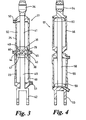
- Such a cylinder unit is illustrated in Fig. 3
- another embodiment is illustrated in Fig. 4 . It is possible without problem to arrange the successive cylinders 25, 26 below the lifting cylinders 23, 24.
- the cylinder units 27, 28 are connected to support structures 32, 33 of the tractor chassis member 31. The free end of each support structure 32, 33 is bifurcated and receives a ball joint 34, 35 of the successive cylinders 25, 26.
- the cylinders are interconnected at the side of the cylinder tube by the common intermediate plate 29, 30 by welding.
- the piston rods 40, 41 carrying the pistons 38, 39 exit at opposite faces of the cylinder unit 27.
- the piston rods 40, 41 include connections 42, 34 for connection with the associated lower link 21 and for pivotal connection with the bearing block 32 at the side of the tractor and being arranged there above.
- Conduits 43, 44 with connections 45, 46 are integrated in the intermediate plate 29, respectively.
- the conduits 43, 44 serve to connect the chamber 47 of the lifting cylinder 23 at the side of the piston with the chamber of the associated assist cylinder 26 at the side of the piston rod (see Fig.
- the chamber 49 of the lifting cylinder 23 at the side of the piston rod as well as the chamber 50 of the assist cylinder 25 at the side of the piston rod includes a pressure medium connection 51, 52.
- lifting cylinders 55 and successive or assist cylinders 56 of a cylinder unit 57 are interconnected by a common piston rod 58.
- Pistons 59, 60 are attached to opposing ends of the piston rod 58.
- the cylinder tubes 61, 62 of the lifting cylinder 55 and of the successive cylinder 56 are arranged to be movable on the piston rod 58.
- the cylinder tubes 61, 62 at their faces include connections 63, 64 for linkage to the respective lower link and the support structure arranged thereabove and being coupled to the tractor.
- the cylinders 55, 56 include pressure medium connections arranged in the same manner as for the cylinder unit according to Fig. 3 .
- actuation of these cylinders is realised in the same way as in the cylinders according to Fig. 3 .
- Actuation of the cylinders according to Figs.1 and 2 is realised in accordance with the hydraulic layout plan illustrated in Fig. 5 .
- the cylinder units 27, 28 illustrated in Figs. 2 and 3 can be replaced by cylinder units 57 according to Fig. 4 . To prevent repetitions, only the actuation of the cylinder units 27, 28 will be described in the following.
- a pump 70 provides a source of pressure medium and is connected to the connection P of a distributing valve 71 including four connections P, T, A and B.
- This distributing valve 71 has four positions I, II, III and IV.
- the connection T is connected to a pressure medium container 72.
- Connection A is connected to the chambers 49, 75 of the lifting cylinders 23, 24 at the side of the piston rod via a controllable check valve 73 closing towards the pump and a distributing valve 74 having a free passage position and a switching position having the effect of a check valve.
- the chamber 47 of the lifting cylinder 23 at the side of the piston is connected to the chamber 77 of its successive or assist cylinder 26 at the side of the piston rod via a conduit 76.
- the chamber 78 of the lifting cylinder 24 at the side of the piston is connected to the chamber 50 of the successive or assist cylinder 25 at the side of the piston rod via a conduit 79.
- the chambers 48, 80 of both successive cylinders 25, 26 at the side of the piston are connected to the connection B via conduits 81, 82 and a controllable check valve 83 closing towards the container 72.
- a conduit 84 branches off from the conduit 82 between the check valve 83 and the successive cylinders 25, 26.
- the conduit 84 bypasses the distributing valve 71 to the container 72.
- a distributing valve 85 having free passage position and a switching position having the effect of a check valve is located in the conduit 84.
- Each cylinder unit 27, 28 is further associated with a distributing valve 86, 87 having free passage switching position and a switching position locking in both directions.
- the distributing valves 86, 87 are located between the conduit 76 and 79, respectively, and a conduit 88 leading to the connection A.
- Both connections A and B are locked in the switching position I of the distributing valve 71 such that there is no pressure medium supply to the cylinders of the cylinder units 27, 28 and no discharge of pressure medium to the container 72 via the distributing valve 71.
- Two functions are available in this switching position:
- the lifting unit with the lower links 21, 22 is rigid and the tool is being moved at the present level when distributing valve 85 has been switched to reach its locking position.
- the lower links are moveable to a certain extent:
- connection A In its switching position II, the connection A is connected to the connection P and the connection B to the connection T.
- a plurality of functions is executable in this switching position.
- each lifting cylinder 23, 24 takes over part of the load of the other lower link by its successive cylinders 26, 25 and the movement of the lower links 21, 22 is achieved in a synchronous way.
- the chambers 48, 80 of the successive cylinders 25, 26, at the side of the piston are connected to the connection B of the distributing valve 71 via conduits 81, 82 such that pressure medium being displaced from these chambers may flow towards the container 72.
- This function is required to be capable of operating a carried tool in a defined inclined position.
- pressure medium streams through the check valve 73, the conduit 88, the distributing valve 86 having its passage position and the conduit 76 into the chamber 47 of the lifting cylinder 23 at the side of the piston as well as into the chamber 77 of the successive cylinder 26 at the side of the piston rod.
- the piston rod 40 is extended with respect to the lifting cylinder 23, and the pressure displaced thereby is pushed into the chamber 75 of the lifting cylinder 24 at the side of the piston rod.
- the respective lower link 22 is pressed in an upward direction, and the tool is pivoted.
- the distributing valve 86 is switched into its locking position, and its then possible to execute the above described function "lifting the lower link” or the below described functions “lowering the lower link” or “eliminating the difference concerning strokes".
- This function corresponds to the above described function with the exception of the carried tool being pivoted in the opposite direction.
- pressure medium streams through the check valve 73, the conduit 88, the distributing valve 87 which is switched into the passage position and the conduit 79, into the chamber 78 of the lifting cylinder 24 at the side of the piston as well as into the chamber 50 of the successive cylinder 25 at the side of the piston rod.
- the piston rod is extended with respect to the lifting cylinder 24, and the pressure medium displaced thereby is pushed into the chamber 49 of the lifting cylinder 23 at the side of the piston rod.
- connections P and B as well as the connections T and A are interconnected. In this case, three functions are available.
- This function may also be used to operate a carried tool in a defined inclined position.
- the chambers 48, 80 of the successive cylinder 25, 26 are pressurised via the check valve 83 and the conduits 82, 81.
- the chamber 78 at the side of the piston and the chamber 50 at the side of the piston are connected with the container 72 and the conduit 88, the distributing valve 87 having its passage position, such that the piston 39 moves in an upward direction with respect to the successive cylinder 25.
- the piston 90 also moves in an upward direction with respect to the successive cylinder 26, pushing pressure medium from the chamber 77 at the side of the piston rod into the chamber 47 at the side of the piston via the conduit 76.
- the piston 38 moves in a downward direction, pushing pressure medium from the chamber 49 into the chamber 75 such that the piston 89 moves in an upward direction. Due to the fact that the amount of pressure medium being displaced from the chamber 77 during this process equals the amount of pressure medium being introduced into the chamber 75, the distance between the pistons 89, 90 moving with respect to their cylinders remains constant. Thus, the entire length of the cylinder unit 28 also remains constant. On the other hand, the entire length of cylinder unit 27 has increased such that the lower link 21 is pressed in a downward direction.
- the distributing valve 87 After having reached the desired difference of strokes and the desired pivot position, respectively, the distributing valve 87 is switched into its locking position, and it is now possible to execute other functions as for example “lifting the lower link”, “lowering the lower link” or “eliminating the difference of strokes” by respectively controlling the distributing valves.
- This function makes it possible to actively press the lower links 21, 22 of the lifting unit in a downward direction, for example to apply an additional force onto the mounted tool of implement. Both lower links 21, 22 move in a synchronous way during the operation of adjustment.
- the distributing valves 86, 87 have been switched to reach the locking position.
- the chambers 48, 80 of the successive cylinders 25, 26 at the side of the piston are subjected to pressure via the check valve 83 and the conduits 82, 81, the successive cylinders 25, 26 increasing in length.
- the pressure medium displaced from the chambers 50, 77 of the successive cylinders 25, 26 at the side of the piston rods flows to the chambers 47, 78 of the associated lifting cylinders 23,24 at the side of the piston such that the length of these cylinders is increased.
- the pressure medium displaced from the chambers 49, 75 of the lifting cylinders 23, 24 at the side of the piston rod flows to the container 72 via the distributing valve 74 in its passage position and the distributing valve 71.
- connections A, B and T are interconnected in switching position IV. Again, two functions are available.
- Both lower links 21, 22 may pivot in a vertical direction independently form another. Due to the fact that the lower links are not guided by the rear axle of the farming tractor in a forced manner, the tool may adapt to unevenness of the ground in an optimal way. For this function, all distributing valves 74, 85, 86, 87 are switched into their passage position such that there is free diffusion of pressure medium between all cylinder chambers 47, 48, 49, 50, 75, 77, 78, 80 and the container 72.
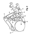
- the lower links 91, 92 are connected to the rear 95 of the vehicle by joints 93.
- a lifting cylinder 98, 99 engages at each lower link 91, 92 at the points of engagement 96, 97.
- the lifting cylinder 98, 99 is supported at the rear 95 by a joint 100, 101.
- a successive or assist cylinder 104, 105 is pivotally connected at sufficient distance to the lifting cylinders 98, 99 and parallel thereto at their sides facing the vehicle and at the points of engagement 102, 103 to the lower links 91, 92.
- the points of engagement 102, 103 are located on the line connecting the joints 93 and the points of engagement 96, 97.
- connection of the successive cylinders 104, 105 at the side of the vehicle is realised by a joint 106 being located on the connecting line 108, 109 of the joint 100, 101 of the lifting cylinder and the joint 93 of the lower links 91, 92.
- the lower links 91, 92 may pivot into a horizontal plane in all pivotal positions without tensions occurring in the lifting unit.
- Actuation of the lifting cylinders 98, 99 and the successive cylinders 104, 105 of this lifting unit is realised in a way corresponding to the actuation of the cylinder of the lifting unit according to Fig. 2 .
Landscapes
- Life Sciences & Earth Sciences (AREA)
- Engineering & Computer Science (AREA)
- Mechanical Engineering (AREA)
- Soil Sciences (AREA)
- Environmental Sciences (AREA)
- Lifting Devices For Agricultural Implements (AREA)
- Forklifts And Lifting Vehicles (AREA)
Description
- The invention relates to a lifting unit for the lower links of a hitch of an agricultural tractor, comprising a pressure medium cylinder arrangement effecting synchronous action of the lower links, the pressure medium cylinder arrangement including first and second lifting cylinders supported at the side of the tractor directly or indirectly and cooperating with the associated lower links in a direct or indirect way.
- A lifting unit including the above mentioned features is known from
German Patent Application DE-OS 199 39 967 A1 . With this lifting unit, it is desired among other things to synchronously pivot the lower links when changing their position, even in the case of the load being unevenly distributed. For this purpose, a control unit is associated with each bottom link, the control unit controlling the supply of pressure medium to the lifting cylinder of the respective lower link by means of the deviation in the signal representing the respective position of the lower link and a predetermined control input. However, in this arrangement, depending on the type of control unit used, a relatively large deviation is necessary to activate the control unit. Since the deviation of both control units during lifting of a tool may differ, it is not necessarily ensured that movement and position of the lower links are synchronised at any point in time. Total uniform movement of both lower links may not be realised in this way. - Apart from the substantial construction and cost expenditure for the required control units and the position sensing elements of the lower links, the known lifting unit has the disadvantage that it is not possible to shift a part of the load of one lower link to the lifting cylinder of the other lower link. In extreme cases in which one of the lower links supports the entire load, the lifting cylinder pivoting this lower link has to be designed to cope with the entire load. Since either of the lifting cylinders could be subjected to the entire load, each lifting cylinder must have a diameter, and be operable at a hydraulic pressure, which can cope with such an eventuality. The lifting cylinders are therefore oversized for the majority of cases of application. Furthermore, it is possible to imagine cases of application in which one of the lower links supports a load being downwardly directed, while an upwardly directed load engages the other lower link. The control unit of the known lifting unit is not capable of realizing synchronous movement of the lower links in this situation without substantial change to the control strategy.
- A hydraulic adjustment unit for height-adjustable agricultural implements is known from
German Patent DE-PS 21 40 882 . The load acting upon a single section of the apparatus is transmitted to a first cylinder by associated second and third cylinders being hydraulically arranged in series with the first cylinder. A hydraulic arrangement including hydraulic cylinders arranged in a series is to be understood herein such that the pressure medium exiting a cylinder located upstream is fed to a downstream cylinder. In this way, only the first cylinder has to be sized with respect to the entire load of the implement, while the other cylinders only have to be sized with respect to the load of the sections of the apparatus being associated with them and being located downstream. When the graduation of the diameters of the cylinders and their operational stroke are correctly chosen, there is synchronous adjustment of the single sections of the apparatus. (However, again, one of the cylinders has a substantial diameter, which is too large for use in a lifting unit for the lower links of an agricultural tractor). - Furthermore, a lifting unit for vehicles is known from JP Abstract 000533388A, the lifting unit includes a lifting table engaged by four lifting cylinders at four different locations. The cylinders are coordinated to form two hydraulically parallel pairs, the cylinders forming a pair being located hydraulically one after the other. A hydraulic parallel arrangement is to be understood such that the respective cylinders are commonly supplied with pressure medium from a source of pressure medium. To realise synchronous adjustment of the lifting table even during unsymmetrical loading, the cylinders of a pair are arranged in a crosswise manner by which the desired effect is achieved. Direct application of this cylinder arrangement in lifting units of agricultural tractors is not possible due to reasons being related to the required space, and due to reasons being especially present in lifting units including pivotal lower links.
- It is the object of the present invention to provide a lifting unit of the kind described above in which the lower links are hydraulically synchronised, which has a technically simple structure and which may be easily mounted in a space efficient manner.
- Thus, according to the present invention there is provided a hitch assembly comprising a hitch assembly comprising a pair of spaced apart lower links, each lower link having respective first and second ends, wherein the first end is pivotally attached to a lower link mount and wherein the second end is free and includes an attachment member, a pair of spaced apart lift actuators connected one to each link, the assembly being characterised in that a pair of spaced apart assist actuators are also connected one to each link, wherein one of the lift actuators and one of the assist actuators are each associated with the first lower link and the other lift actuator and assist actuator are each associated with the second lower link, the lift actuator associated with the first lower link being hydraulically connected in series with the assist actuator associated with the second lower link, and the lift actuator associated with the second lower link being hydraulically connected in series with the assist actuator associated with the first lower link.
- Due to the above cross connection of the lift actuator of one link with the assist actuator of the other link, it is possible to realise exact synchronous movement of the lower links independent from the distribution of the load of the implement onto the lower links since any asynchronous movement is prevented by the mutually locking actuators.
- Additional details and features of the invention are described in the dependent claims. The mechanical serial connection of the lifting actuators and assist cylinders actuators allows for arrangement of the actuators without problem and clear transfer of the forces of the actuators acting upon the lower links. In this way, tensions and space-related problems are prevented. These problems may occur in a mechanical parallel arrangement of the cylinders due to the pivoting lower links.
- Due to the connection of the lifting actuator and the assist actuator by a transmitting element and the addition of their changes of length (strokes) resulting therefrom, comparatively short actuators may be used. These may be located at different positions of the lifting unit if the transmitting element is a lever pivotally connected to the tractor. This does not only simplify their arrangement, but it may also be used to increase their effective stroke by means of the possible lever transmission. However, the lifting actuators and the assist actuators may also be combined to form one structural unit to decrease the manufacturer expenditure.
- In an especially simple structural unit, a piston with a piston rod is associated with each actuator of the structural unit, the piston rods exiting at opposite sides of the structural unit and including coupling means for connection to the apparatus and load, respectively.
- In another alternative construction for a combined lift and assist actuator a common piston rod with a piston at each end is needed. This is a low cost arrangement.
- A horizontal pivotal movement of the lower links without tensions occurring in the lifting unit is realised by an embodiment in which the lifting actuators and the assist actuators are supported at the rear of the vehicle. In this arrangement each assist actuator engages its lower link on a line connecting the lift cylinder connection point with that link with the link pivot connection on the tractor.
- In the drawings, which illustrate exemplary embodiments of the invention:
- Fig 1.
- illustrates a first exemplary embodiment of a hitch assembly in accordance with the invention in which the lifting cylinders and the assist cylinders are connected to a pair of lift arms;
- Fig 2.
- illustrates a second exemplary embodiment of a hitch assembly in accordance with the invention in which the lift and assist cylinders are combined into an integral structural unit;
- Fig 3.
- illustrates a section view of the integral structural unit shown in
Fig 2 ; - Fig 4.
- illustrates a sectional view of a further example of an integral structural unit;
- Fig 5.
- illustrates a plan of a hydraulic control arrangement for the hitch assembly of
Fig 2 ; and - Fig 6.
- illustrates a third exemplary embodiment of a hitch assembly in accordance with the invention in which the lift and assist cylinders directly engaging the lower links,
- The lifting unit or hitch assembly illustrated in
Fig. 1 is arranged on the rear 1 of a tractor (not illustrated). The lifting unit itself is also only illustrated to an extent being necessary for understanding the invention. The lifting unit includes twolower links 2, 3 pivotally connected atlocation 6 to the rear 1. The end portions of thelower links 2, 3 at the side of the tractor are located at a low level. Thelower links 2, 3 substantially extend in a rear direction as seen in the longitudinal direction of the vehicle. Theother end portions 4, 5 of thelower links 2, 3 are adapted to receive coupling members of tools to be carried by the lifting unit. Alifting arm 9, 10 is pivotally supported on the rear 1 at the pivot locations 7, 8, above thepivot location 6 of eachlower link 2, 3. Thelifting arm 9, 10 also substantially extends in a rearward direction as seen in the longitudinal direction of the vehicle.Lifting cylinders 11, 12 are supported at the rear 1, adjacent to thepivot locations 6 of thelower links 2, 3 their other ends engaging thelocations lifting arm 9, 10 to pivot thelifting arm 9, 10. - Another cylinder engages the free end of the
lifting arm 9, 10. In the following, this cylinder will be designated as the successive or assistcylinder assist cylinder lower links 2, 3 by abifurcated head cylinders 11, 12 and theassist cylinders cylinders lower links 2, 3 during actuation, the changes of lengths geometrically summing up. The change of length is further increased by the lever transmissions of the liftingarms 9, 10. The lever transmission depends on the distance between thepivot locations cylinders 11, 12 and thepivot locations cylinders lifting arm 9, 10. In the described exemplary embodiment, the lifting cylinders are arranged close to the vehicle. Without substantially departing from the spirit of the present invention, the lifting cylinders may be easily interchanged with the successive cylinders, meaning they may be arranged comparatively far away from the vehicle. - Pressurization of the
cylinders 11, 12 15, 16 is realised as illustrated inFig.5 , and is explained in greater detail with respect toFig.2 . The two liftingcylinders 11, 12 are hydraulically arranged to be parallel, i.e. they are simultaneously supplied by a common pressure medium source via a 4/4 way valve. It is important that theassist cylinders assist cylinder 16 of the lifting cylinder 11 engaging thelower link 2 engages the other lower link 3. Theassist cylinder 15 of the liftingcylinder 12 engaging the lower link 3 likewise engages thelower link 2. Due to the fact that theassist cylinders cylinders 12, 11 are hydraulically arranged one after the other, pressure medium displaced from the liftingcylinders 11, 12 during their actuation in the sense of lifting thelower links 2, 3 is fed to the associatedassist cylinder cylinder 11, 12 is designed for half of the entire load of the tool to be carried such that both lifting cylinders have the same relatively small diameter. To prevent tensions occurring in the lifting unit, the diameter and the maximum working stroke of the successive cylinders are matched with the relevant size of the lifting cylinders. In this way, thelower links 2, 3 move in a synchronous way during pressurization of the liftingcylinders 11, 12 as long as there is no substantial loss of pressure medium at theassist cylinders lower links 2, 3. The loss of pressure medium usually occurring in such apparatuses is of no importance in this context. - The exemplary embodiment illustrated in
Fig. 2 substantially corresponds to the one ofFig. 1 . In contrast thereto, the liftingcylinders cylinders lower links cylinder units successive cylinders cylinders intermediate plate Fig. 3 , and another embodiment is illustrated inFig. 4 . It is possible without problem to arrange thesuccessive cylinders cylinders cylinder units structures tractor chassis member 31. The free end of eachsupport structure successive cylinders - In the exemplary embodiment according to
Fig. 3 in which thelifting cylinder 23 an thesuccessive cylinder 25 form acylinder unit 27, the cylinders are interconnected at the side of the cylinder tube by the commonintermediate plate piston rods pistons cylinder unit 27. Thepiston rods connections lower link 21 and for pivotal connection with the bearingblock 32 at the side of the tractor and being arranged there above.Conduits connections intermediate plate 29, respectively. Theconduits chamber 47 of the liftingcylinder 23 at the side of the piston with the chamber of the associatedassist cylinder 26 at the side of the piston rod (seeFig. 2 ) and to feed/discharge pressure medium to/from thechamber 48 of thesuccessive cylinder 25 at the side of the piston, respectively. Furthermore, thechamber 49 of the liftingcylinder 23 at the side of the piston rod as well as thechamber 50 of theassist cylinder 25 at the side of the piston rod includes apressure medium connection - In the exemplary embodiment of
Fig. 4 , liftingcylinders 55 and successive or assistcylinders 56 of acylinder unit 57 are interconnected by acommon piston rod 58.Pistons piston rod 58. The cylinder tubes 61, 62 of the liftingcylinder 55 and of thesuccessive cylinder 56 are arranged to be movable on thepiston rod 58. The cylinder tubes 61, 62 at their faces includeconnections cylinders Fig. 3 . Thus, actuation of these cylinders is realised in the same way as in the cylinders according toFig. 3 . - Actuation of the cylinders according to
Figs.1 and2 is realised in accordance with the hydraulic layout plan illustrated inFig. 5 . Thecylinder units Figs. 2 and3 can be replaced bycylinder units 57 according toFig. 4 . To prevent repetitions, only the actuation of thecylinder units - A
pump 70, provides a source of pressure medium and is connected to the connection P of a distributingvalve 71 including four connections P, T, A and B. This distributingvalve 71 has four positions I, II, III and IV. The connection T is connected to a pressuremedium container 72. Connection A is connected to thechambers cylinders controllable check valve 73 closing towards the pump and a distributingvalve 74 having a free passage position and a switching position having the effect of a check valve. Thechamber 47 of the liftingcylinder 23 at the side of the piston is connected to thechamber 77 of its successive or assistcylinder 26 at the side of the piston rod via aconduit 76. In the same way, thechamber 78 of the liftingcylinder 24 at the side of the piston is connected to thechamber 50 of the successive or assistcylinder 25 at the side of the piston rod via aconduit 79. Thechambers successive cylinders conduits controllable check valve 83 closing towards thecontainer 72. Aconduit 84 branches off from theconduit 82 between thecheck valve 83 and thesuccessive cylinders conduit 84 bypasses the distributingvalve 71 to thecontainer 72. A distributingvalve 85 having free passage position and a switching position having the effect of a check valve is located in theconduit 84. Eachcylinder unit valve valves conduit conduit 88 leading to the connection A. - Both connections A and B are locked in the switching position I of the distributing
valve 71 such that there is no pressure medium supply to the cylinders of thecylinder units container 72 via the distributingvalve 71. Two functions are available in this switching position: - The lifting unit with the
lower links valve 85 has been switched to reach its locking position. - When the distributing
valve 85 has been switched to reach passage position, there is transfer of pressure medium towards and away form thecontainer 72. Due to the fact that thesuccessive cylinders lower links - In its switching position II, the connection A is connected to the connection P and the connection B to the connection T. A plurality of functions is executable in this switching position.
- During this function, pressure medium streams through the
check valve 73, the distributingvalve 74 being switched to reach the passage position into thechambers cylinders pistons lower links pressure chambers pressure chambers successive cylinders cylinders lower link lower link cylinder successive cylinders lower links chambers successive cylinders valve 71 viaconduits container 72. - This function is required to be capable of operating a carried tool in a defined inclined position. With this function, pressure medium streams through the
check valve 73, theconduit 88, the distributingvalve 86 having its passage position and theconduit 76 into thechamber 47 of the liftingcylinder 23 at the side of the piston as well as into thechamber 77 of thesuccessive cylinder 26 at the side of the piston rod. Thepiston rod 40 is extended with respect to thelifting cylinder 23, and the pressure displaced thereby is pushed into thechamber 75 of the liftingcylinder 24 at the side of the piston rod. Due to the fact that thechamber 48 of thesuccessive cylinder 25 at the side of the piston is connected to thecontainer 72 by the distributingvalve 85, pressure medium may stream from thechamber 78 of the liftingcylinder 24 at the side of the piston into thechamber 50 of thesuccessive cylinder 25 at the side of the piston rod, and thepiston rod 41 may thus move inwardly with respect to thesuccessive cylinder 25. During this process, the length of thecylinder unit 27 remains constant since the relative movement of thepiston rods chamber 80 of thesuccessive cylinder 26 at the side of the piston rod is also connected to thecontainer 72, the piston rods of bothcylinders cylinder unit 28 decreases. The respectivelower link 22 is pressed in an upward direction, and the tool is pivoted. After reaching the desired difference concerning strokes and the desired pivoted position of the tool, respectively, the distributingvalve 86 is switched into its locking position, and its then possible to execute the above described function "lifting the lower link" or the below described functions "lowering the lower link" or "eliminating the difference concerning strokes". - This function corresponds to the above described function with the exception of the carried tool being pivoted in the opposite direction. During this function, pressure medium streams through the
check valve 73, theconduit 88, the distributingvalve 87 which is switched into the passage position and theconduit 79, into thechamber 78 of the liftingcylinder 24 at the side of the piston as well as into thechamber 50 of thesuccessive cylinder 25 at the side of the piston rod. The piston rod is extended with respect to thelifting cylinder 24, and the pressure medium displaced thereby is pushed into thechamber 49 of the liftingcylinder 23 at the side of the piston rod. Due to the fact that thechamber 80 of thesuccessive cylinder 26 at the side of the piston rod is connected to thecontainer 72 by the distributingvalve 85, pressure medium may stream form thechamber 47 of the liftingcylinder 23 at the side of the piston rod into thechamber 77 at the side of the piston rod, and consequently the piston rod moves in an inward direction with respect to thesuccessive cylinder 26. During this process, the length of thecylinder unit 28 remains constant since the relative movements of the piston rods of bothcylinders chamber 48 of thesuccessive cylinder 25 at the side of the piston is also connected to thecontainer 72, the piston rods of bothcylinders cylinder 27 decreases. The respectivelower link 21 is then pressed in an upward direction, and the tool is pivoted in an opposite direction compared to the above described function. After having reached the desired difference concerning strokes and the desired pivoted position, respectively, the distributingvalve 87 is switched to reach its locking position, and it is again possible to execute the above described function "lifting the lower link" or the below described functions "eliminating the difference concerning strokes" or "lowering the lower link". - This function makes it possible to cancel a previously adjusted difference concerning strokes. The
lower links chambers cylinders chamber 78 of the liftingcylinder 24 at the side of the piston as well as thechamber 50 of itssuccessive cylinder 25 at the side of the piston rod pressurised by pressure medium from the distributingvalve 87 in its passage position and theconduit 79. The same applies to thechamber 47 of the liftingcylinder 23 at the side of the piston and thechamber 77 of thesuccessive cylinder 26 at the side of the piston rod via the distributingvalve 86 which has also been switched to reach its passage position and theconduit 76. During this process, the twolower links cylinder units - The same result may be achieved with the distributing
valve 71 being switched to switching position III. Further details will be explained with respect to this switching position. - In the switching position III of the distributing
valve 71, the connections P and B as well as the connections T and A are interconnected. In this case, three functions are available. - This function may also be used to operate a carried tool in a defined inclined position. With this function, the
chambers successive cylinder check valve 83 and theconduits chamber 78 at the side of the piston and thechamber 50 at the side of the piston are connected with thecontainer 72 and theconduit 88, the distributingvalve 87 having its passage position, such that thepiston 39 moves in an upward direction with respect to thesuccessive cylinder 25. Thepiston 90 also moves in an upward direction with respect to thesuccessive cylinder 26, pushing pressure medium from thechamber 77 at the side of the piston rod into thechamber 47 at the side of the piston via theconduit 76. Thepiston 38 moves in a downward direction, pushing pressure medium from thechamber 49 into thechamber 75 such that thepiston 89 moves in an upward direction. Due to the fact that the amount of pressure medium being displaced from thechamber 77 during this process equals the amount of pressure medium being introduced into thechamber 75, the distance between thepistons cylinder unit 28 also remains constant. On the other hand, the entire length ofcylinder unit 27 has increased such that thelower link 21 is pressed in a downward direction. After having reached the desired difference of strokes and the desired pivot position, respectively, the distributingvalve 87 is switched into its locking position, and it is now possible to execute other functions as for example "lifting the lower link", "lowering the lower link" or "eliminating the difference of strokes" by respectively controlling the distributing valves. - This function makes it possible to actively press the
lower links lower links valves chambers successive cylinders check valve 83 and theconduits successive cylinders chambers successive cylinders chambers cylinders chambers cylinders container 72 via the distributingvalve 74 in its passage position and the distributingvalve 71. - When applying the function "pressing the lower link downwards", a difference of strokes is automatically cancelled in the lowermost position of the
lower links - The connections A, B and T are interconnected in switching position IV. Again, two functions are available.
- Both
lower links valves cylinder chambers container 72. - For applying this function, all distributing
valves valve 74 are switched into the locking position. The pressure medium which is subject to pressure corresponding to the weight of the tool, and which is located in thechambers cylinders chambers successive cylinders valve 74 and the distributingvalve 71. - In the exemplary embodiment of a lifting unit according to
Fig. 6 , thelower links joints 93. A liftingcylinder lower link engagement cylinder cylinder cylinders engagement lower links engagement joints 93 and the points ofengagement successive cylinders line lower links lower links cylinders successive cylinders Fig. 2 . Again, it is essential that thesuccessive cylinder 105 of the liftingcylinder 98 together with the liftingcylinder 98 engages thelower link 91. The pressure medium being displaced from the liftingcylinders successive cylinders lower links lower links cylinders lower link 91 have to fulfil different strokes during its pivotal movement. This fact is taken into account by a respective choice of, for example, the outer diameter of thesuccessive cylinder 104.
Claims (13)
- A hitch assembly comprising a pair of spaced apart lower links (2,3), each lower link having respective first and second ends, wherein the first end is pivotally attached to a lower link mount (6) and wherein the second end is free and includes an attachment member (4,5), a pair of spaced apart lift actuators (11,12) connected one to each link, the assembly being characterised in that a pair of spaced apart assist actuators (15,16) are also connected one to each link, wherein one of the lift actuators and one of the assist actuators are each associated with the first lower link and the other lift actuator and assist actuator are each associated with the second lower link, the lift actuator (11) associated with the first lower link (2) being hydraulically connected in series with the assist actuator (16) associated with the second lower link (3), and the lift actuator associated (12) with the second lower link (3) being hydraulically connected in series with the assist actuator (15) associated with the first lower link (2).
- A hitch assembly according to Claim 1, wherein lift actuator (11,12) and assist actuator (15,16) associated with a respective one of the lower links are arranged mechanically in a series, thereby summing their working strokes.
- A hitch assembly according to Claim 2, wherein the lift actuator (11,12) and assist actuator (15,16) associated with a respective lower link are connected by a transmitting element (9,10) which transmits any change of length of the lift actuator to its associated assist actuator.
- A hitch assembly according to Claims 2 or 3, wherein the lift and assist actuator are hydraulic rams (23,24:25,26) each comprising a piston (38,39:89,90) and a cylinder, said actuators having a common axis and forming a hydraulic cylinder unit (27,28).
- A hitch assembly according to Claim 4 wherein associated lift and assist actuators (23,24:25,26) are fixedly interconnected by a common intermediate plate (29,30) including integrated inlet/outlet bores (43,44:45,46) to form a integrated hydraulic cylinder unit (27,28).
- A hitch assembly according to Claim 4 or 5, wherein each hydraulic cylinder unit (27,28) includes a piston rod (40,41), respective ends of the piston rod exiting at opposite sides of the cylinder unit and including coupling means (34,42) for pivotal connection with the vehicle carrying said hitch and the lower links respectively.
- A hitch assembly according to Claim 4, wherein the lift actuator (55) and the assist actuator (56) are fixedly interconnected by a common piston rod (58) to form the cylinder unit (57).
- A hitch assembly according to Claim 7, wherein the piston rod (58) at each of its ends carries a piston (59,60), and wherein coupling means (63,64) for pivotal connection of the cylinder unit with the vehicle and with the lower links, are arranged at opposite ends of the cylinder unit (57) respectively.
- A hitch according to Claim 3, wherein the transmitting element is a lever (9,10) pivotally mounted at one end thereof (7,8) to the vehicle (1) and to which a lift actuator (11,12) is coupled at a distance from the pivot mount and to which the assist actuator (15,16) is coupled at the same or a greater distance from the pivot mount.
- A hitch assembly according to Claim 1, wherein the lift (98,99) and assist (104,105) actuators are supported at the rear of the vehicle (95), and the force generated by associated lift and assist actuators is summed.
- A hitch assembly according to Claim 10, wherein associated lift (98,99) and assist (104,105) actuators are each pivotally attached at a first end (96,97:102,103) to a lower link (91,92) and at a second end (100,101:106) to the vehicle (95), wherein the pivotal attachment (93) of the lower link to the vehicle and the pivotal attachments (106:100,101) of the associated lift and assist actuators to the vehicle (95) are substantially aligned (108,109).
- A hitch assembly according to Claim 11, wherein the pivotal attachments (96,97:102,103) of the actuators (98,99:104,105) to the lower links (91,92), and the pivotal attachment (93) of the lower link to the vehicle (95) are substantially aligned.
- A hitch assembly according to any one of the claims 1 to 12 having a hydraulic control arrangement for the actuators comprising:- a four way distributor valve (71) having four switching positions (I,II,III,IV) and four connections (A,B,P,T), the four way valve (71) being arranged between on the one side conduits (88,82) connected with the actuators and on the other side a pump (70) and a hydraulic fluid container (72);- a second distributor valve (86) for connecting and disconnecting one conduit (88) with a piston head chamber (47) of the lift actuator (23) of the first link (21) and with a piston rod chamber (77) of the assist actuator (28) of the second link (22);- a third distributor valve (87) for connecting and disconnecting said one conduit (88) with a piston head chamber (78) of the lift actuator (24) of the second link and with a piston rod chamber (50) of the assist actuator (27) of the first link (21);- a fourth distributor valve (74) for connecting and disconnecting the piston rod chambers (49, 75) of the lift actuators (23,24) with said one conduit (88); and- a fifth distributor valve (85) for connecting and disconnecting the other conduit (83), which is connected with the piston head chambers (48,80) of the assist actuators (27,28), with the fluid container (72) by bypassing the four way distributor valve (71).
Applications Claiming Priority (2)
| Application Number | Priority Date | Filing Date | Title |
|---|---|---|---|
| GB0304432A GB2398720B (en) | 2003-02-27 | 2003-02-27 | Lifting unit for the lower links of a tractor |
| GB0304432 | 2003-02-27 |
Publications (2)
| Publication Number | Publication Date |
|---|---|
| EP1452082A1 EP1452082A1 (en) | 2004-09-01 |
| EP1452082B1 true EP1452082B1 (en) | 2009-07-22 |
Family
ID=9953723
Family Applications (1)
| Application Number | Title | Priority Date | Filing Date |
|---|---|---|---|
| EP04002209A Expired - Lifetime EP1452082B1 (en) | 2003-02-27 | 2004-02-02 | Lifting unit for the lower links of a tractor |
Country Status (3)
| Country | Link |
|---|---|
| EP (1) | EP1452082B1 (en) |
| DE (1) | DE602004022097D1 (en) |
| GB (1) | GB2398720B (en) |
Families Citing this family (6)
| Publication number | Priority date | Publication date | Assignee | Title |
|---|---|---|---|---|
| AU2003282214A1 (en) | 2002-10-28 | 2004-05-13 | Splashpower Limited | Unit and system for contactless power transfer |
| FR2937827B1 (en) * | 2008-10-30 | 2013-02-15 | Hubert Defrancq | FRONT LIFTING DEVICE FOR TRACTOR. |
| CN103283333B (en) * | 2013-05-27 | 2015-12-23 | 李红军 | Tractor suspension hydraulic rises device by force |
| ITPD20130161A1 (en) * | 2013-06-05 | 2014-12-06 | Carraro Antonio Spa | LIFTING AND SUSPENSION DEVICE FOR TOWING AGRICULTURAL EQUIPMENT FOR SIMILAR TRACTORS AND MACHINES |
| EP2950422A1 (en) * | 2014-05-16 | 2015-12-02 | Samsung Electro-Mechanics Co., Ltd. | Wireless charging transmitter and wireless charging system using the same |
| DE102017102114A1 (en) * | 2017-02-03 | 2018-08-09 | Amazonen-Werke H. Dreyer Gmbh & Co. Kg | Hydraulic actuator for an agricultural tillage machine |
Family Cites Families (8)
| Publication number | Priority date | Publication date | Assignee | Title |
|---|---|---|---|---|
| FR1280050A (en) * | 1960-11-16 | 1961-12-29 | Int Harvester Co | Hydraulic depth control device for tillage implements |
| US3663032A (en) * | 1970-11-02 | 1972-05-16 | Deere & Co | Hydraulic depth control for agricultural implements |
| DE2854188A1 (en) * | 1978-12-15 | 1980-06-26 | Ernst Conrad | Hydraulic adjuster for tractor three point linkages - has two piston and cylinder units, one used as adjuster and one as arrester |
| DE3423194A1 (en) * | 1984-06-22 | 1986-01-02 | Ernst 3101 Nienhagen Conrad | Device for arresting the elevating movement of power lifts |
| DE3607257A1 (en) * | 1986-03-05 | 1987-09-10 | Fritzmeier Georg Gmbh & Co | Device for additional loading of a working appliance mounted in the floating position on an agricultural tractor |
| AT388483B (en) * | 1988-03-30 | 1989-06-26 | Steyr Daimler Puch Ag | LIFTING ROD TO CONNECT THE LIFTING ARMS TO THE LOWER ARMS IN A HYDRAULIC TRACTOR LIFT |
| DE19939967C2 (en) | 1999-01-09 | 2003-10-23 | Walterscheid Gmbh Gkn | Hoist for lower links of an attachment device of a tractor |
| EP1018292B8 (en) * | 1999-01-09 | 2005-06-29 | GKN Walterscheid GmbH | Tractor hitch lower link lifting device |
-
2003
- 2003-02-27 GB GB0304432A patent/GB2398720B/en not_active Expired - Fee Related
-
2004
- 2004-02-02 DE DE602004022097T patent/DE602004022097D1/en not_active Expired - Lifetime
- 2004-02-02 EP EP04002209A patent/EP1452082B1/en not_active Expired - Lifetime
Also Published As
| Publication number | Publication date |
|---|---|
| GB0304432D0 (en) | 2003-04-02 |
| DE602004022097D1 (en) | 2009-09-03 |
| GB2398720A (en) | 2004-09-01 |
| GB2398720B (en) | 2006-04-12 |
| EP1452082A1 (en) | 2004-09-01 |
Similar Documents
| Publication | Publication Date | Title |
|---|---|---|
| CA2580592C (en) | Front fold planter lift and fold hydraulic control system | |
| KR101960998B1 (en) | Agricultural tractor | |
| US4960242A (en) | Asphalt distributor | |
| RU2571068C2 (en) | Valve system | |
| EP0800471B1 (en) | Leg mechanism | |
| CN101918302A (en) | Travelable Work Machinery | |
| US10760594B2 (en) | Hydraulic cylinder supply system | |
| EP1452082A1 (en) | Lifting unit for the lower links of a tractor | |
| CN106917431A (en) | The hydraulic system of Work machine | |
| EP1018292B1 (en) | Tractor hitch lower link lifting device | |
| EP3321515A1 (en) | Hydraulic cylinder supply system | |
| US6109378A (en) | Leg mechanism | |
| GB2376403A (en) | A hydraulic lifting device for an attachment mechanism of a tractor | |
| AU2003215983B2 (en) | A trailer for a boat | |
| US5860233A (en) | Valve configuration and mounting arrangement | |
| KR100342109B1 (en) | A hydrauric hoist which is controllable with regard to position and applied force, for tractors and agricultural machines, and distributor therefor | |
| US4892158A (en) | Three point coupling arrangement for a tractor | |
| DE202007015638U1 (en) | agricultural machinery | |
| US4293040A (en) | Hydraulic draft load sensing system including quill shaft bendable in response to draft loads | |
| CN215898371U (en) | Chassis leveling system, chassis and agricultural machine | |
| CN110344460B (en) | Hydraulic control circuit for an articulation assembly | |
| JP4033413B2 (en) | Scatter work vehicle | |
| US3994347A (en) | Draft control system with control valve | |
| NL7905196A (en) | MOVABLE HARVESTER. | |
| NL1005230C2 (en) | Control unit for lorry-mounted hydraulic crane |
Legal Events
| Date | Code | Title | Description |
|---|---|---|---|
| PUAI | Public reference made under article 153(3) epc to a published international application that has entered the european phase |
Free format text: ORIGINAL CODE: 0009012 |
|
| AK | Designated contracting states |
Kind code of ref document: A1 Designated state(s): AT BE BG CH CY CZ DE DK EE ES FI FR GB GR HU IE IT LI LU MC NL PT RO SE SI SK TR |
|
| AX | Request for extension of the european patent |
Extension state: AL LT LV MK |
|
| 17P | Request for examination filed |
Effective date: 20050121 |
|
| AKX | Designation fees paid |
Designated state(s): AT DE FI FR GB IT |
|
| RBV | Designated contracting states (corrected) |
Designated state(s): AT DE FI FR GB IT |
|
| RAP1 | Party data changed (applicant data changed or rights of an application transferred) |
Owner name: AGCO GMBH |
|
| GRAP | Despatch of communication of intention to grant a patent |
Free format text: ORIGINAL CODE: EPIDOSNIGR1 |
|
| GRAS | Grant fee paid |
Free format text: ORIGINAL CODE: EPIDOSNIGR3 |
|
| GRAA | (expected) grant |
Free format text: ORIGINAL CODE: 0009210 |
|
| AK | Designated contracting states |
Kind code of ref document: B1 Designated state(s): AT DE FI FR GB IT |
|
| REG | Reference to a national code |
Ref country code: GB Ref legal event code: FG4D |
|
| REF | Corresponds to: |
Ref document number: 602004022097 Country of ref document: DE Date of ref document: 20090903 Kind code of ref document: P |
|
| PG25 | Lapsed in a contracting state [announced via postgrant information from national office to epo] |
Ref country code: FI Free format text: LAPSE BECAUSE OF FAILURE TO SUBMIT A TRANSLATION OF THE DESCRIPTION OR TO PAY THE FEE WITHIN THE PRESCRIBED TIME-LIMIT Effective date: 20090722 Ref country code: AT Free format text: LAPSE BECAUSE OF FAILURE TO SUBMIT A TRANSLATION OF THE DESCRIPTION OR TO PAY THE FEE WITHIN THE PRESCRIBED TIME-LIMIT Effective date: 20090722 |
|
| PLBE | No opposition filed within time limit |
Free format text: ORIGINAL CODE: 0009261 |
|
| STAA | Information on the status of an ep patent application or granted ep patent |
Free format text: STATUS: NO OPPOSITION FILED WITHIN TIME LIMIT |
|
| 26N | No opposition filed |
Effective date: 20100423 |
|
| PGFP | Annual fee paid to national office [announced via postgrant information from national office to epo] |
Ref country code: FR Payment date: 20120227 Year of fee payment: 9 |
|
| PGFP | Annual fee paid to national office [announced via postgrant information from national office to epo] |
Ref country code: DE Payment date: 20120221 Year of fee payment: 9 |
|
| PGFP | Annual fee paid to national office [announced via postgrant information from national office to epo] |
Ref country code: GB Payment date: 20120221 Year of fee payment: 9 Ref country code: IT Payment date: 20120229 Year of fee payment: 9 |
|
| GBPC | Gb: european patent ceased through non-payment of renewal fee |
Effective date: 20130202 |
|
| REG | Reference to a national code |
Ref country code: FR Ref legal event code: ST Effective date: 20131031 |
|
| REG | Reference to a national code |
Ref country code: DE Ref legal event code: R119 Ref document number: 602004022097 Country of ref document: DE Effective date: 20130903 |
|
| PG25 | Lapsed in a contracting state [announced via postgrant information from national office to epo] |
Ref country code: IT Free format text: LAPSE BECAUSE OF NON-PAYMENT OF DUE FEES Effective date: 20130202 |
|
| PG25 | Lapsed in a contracting state [announced via postgrant information from national office to epo] |
Ref country code: DE Free format text: LAPSE BECAUSE OF NON-PAYMENT OF DUE FEES Effective date: 20130903 Ref country code: FR Free format text: LAPSE BECAUSE OF NON-PAYMENT OF DUE FEES Effective date: 20130228 Ref country code: GB Free format text: LAPSE BECAUSE OF NON-PAYMENT OF DUE FEES Effective date: 20130202 |