EP1451407B1 - Method of forming a fibrous web and machine therefor - Google Patents
Method of forming a fibrous web and machine therefor Download PDFInfo
- Publication number
- EP1451407B1 EP1451407B1 EP02780249A EP02780249A EP1451407B1 EP 1451407 B1 EP1451407 B1 EP 1451407B1 EP 02780249 A EP02780249 A EP 02780249A EP 02780249 A EP02780249 A EP 02780249A EP 1451407 B1 EP1451407 B1 EP 1451407B1
- Authority
- EP
- European Patent Office
- Prior art keywords
- blade means
- water
- paper machine
- blade
- machine according
- Prior art date
- Legal status (The legal status is an assumption and is not a legal conclusion. Google has not performed a legal analysis and makes no representation as to the accuracy of the status listed.)
- Expired - Lifetime
Links
- 238000000034 method Methods 0.000 title claims description 15
- XLYOFNOQVPJJNP-UHFFFAOYSA-N water Substances O XLYOFNOQVPJJNP-UHFFFAOYSA-N 0.000 claims abstract description 76
- 239000000835 fiber Substances 0.000 claims abstract description 52
- 239000000725 suspension Substances 0.000 claims abstract description 49
- 230000000694 effects Effects 0.000 claims abstract description 8
- 238000011144 upstream manufacturing Methods 0.000 claims description 8
- 238000005086 pumping Methods 0.000 claims description 6
- 239000011148 porous material Substances 0.000 claims description 3
- 239000010410 layer Substances 0.000 description 33
- 239000000463 material Substances 0.000 description 5
- 238000005192 partition Methods 0.000 description 4
- 239000003086 colorant Substances 0.000 description 1
- 238000010276 construction Methods 0.000 description 1
- 238000004519 manufacturing process Methods 0.000 description 1
- 239000002344 surface layer Substances 0.000 description 1
Images


Classifications
-
- D—TEXTILES; PAPER
- D21—PAPER-MAKING; PRODUCTION OF CELLULOSE
- D21F—PAPER-MAKING MACHINES; METHODS OF PRODUCING PAPER THEREON
- D21F11/00—Processes for making continuous lengths of paper, or of cardboard, or of wet web for fibre board production, on paper-making machines
- D21F11/02—Processes for making continuous lengths of paper, or of cardboard, or of wet web for fibre board production, on paper-making machines of the Fourdrinier type
- D21F11/04—Processes for making continuous lengths of paper, or of cardboard, or of wet web for fibre board production, on paper-making machines of the Fourdrinier type paper or board consisting on two or more layers
-
- D—TEXTILES; PAPER
- D21—PAPER-MAKING; PRODUCTION OF CELLULOSE
- D21F—PAPER-MAKING MACHINES; METHODS OF PRODUCING PAPER THEREON
- D21F1/00—Wet end of machines for making continuous webs of paper
- D21F1/02—Head boxes of Fourdrinier machines
-
- D—TEXTILES; PAPER
- D21—PAPER-MAKING; PRODUCTION OF CELLULOSE
- D21F—PAPER-MAKING MACHINES; METHODS OF PRODUCING PAPER THEREON
- D21F1/00—Wet end of machines for making continuous webs of paper
- D21F1/02—Head boxes of Fourdrinier machines
- D21F1/028—Details of the nozzle section
Definitions
- water is pumped through the blade means in internal channels in order to obtain a pressure drop, which will assure that the water flow rate is the same in all channels.
- the channels terminate preferably at a distance from the water outlet at the end of the blade means in order to provide a uniform flow rate of the water coming out from the blade means.
- the blade means is movable in such a way that it is elastically deformable and thereby permitting the equalization of pressure between the fibre suspension layers.
- the blade means can comprise a pair of parallel mutually spaced sheets, arranged above each other and substantially parallel to the direction of the intended water flow.
- the blade means can comprise a pair of sheets, which are arranged above each other and converge towards each other in the direction of the intended water flow, whereby the outlet from the blade means is narrower than the inlet.
Landscapes
- Paper (AREA)
- Preliminary Treatment Of Fibers (AREA)
Abstract
Description
- The present invention relates to a method of forming a layered fibrous web and a machine therefore.
- In the paper industry, it is often desirable to form multi-layered fibrous pulp webs, where different fibre suspensions are used in the different layers. A paper can for example consist of a core made of recycled fibre material while the surface layers consist of a different fibre material in order to give the paper a desired surface. Such multi-layered webs can be produced by means of layered head boxes, where the different fibre suspensions are separated by means of one or more blade. At the outlet of the head box, the fibre suspension layers are dispensed on top of each other on a paper forming wire and thereby forming a multi-layered fibrous pulp web. Since the different layers often consist of materials with different fibre properties or even different colours, it is essential to prevent mixing of the layers. The mixing is mainly caused by the wake that is formed behind the trailing edge of the blade. These wakes generate strong turbulent mixing, which effectively prevents the possibility to obtain a good layer purity. Several attempts to solve this problem have been made.
- The British patent application GB-A-2107751 discloses a paper machine and a process for producing a multi-layer fibrous pulp web, where two layers of fibre suspension are separated by an intermediate flow duct through which water is flowing and thereby forming a separating layer between the fibre suspension layers. Said flow duct extends from the inlet end of the head box up to approximately the centre of the head box and consists of rigid partition walls. This construction requires a symmetrical position of the blades in the head box in order to achieve equal pressure on both sides of the blade at the trailing edge. Also, severe mixing will take place unless the partition walls forming the flow duct are extremely accurately positioned, which in reality is practically impossible. As a consequence of this, it is not possible to feed different volume flows of fibre suspension separated by the partition walls without causing an unwanted difference in pressure between the fibre suspension layers. The positioning of the partition walls in order to achieve equal pressure on both sides of the blade must furthermore be adapted for one specific speed of the fibre suspension, which makes the paper machine inflexible to use.
- The object of the invention is to solve the problems related to the prior art. This is achieved by means of a method according to claim 1. More specific, the present invention relates to a method of forming a layered fibrous web, comprising leading at least two different fibre suspensions through a head box, separating the fibre suspensions from each other by a blade means, supplying the fibre suspensions to a web forming device and forming a water layer having a transversely uniform flow at an outlet at the end of the blade means, such that the water layer constitutes an extension of the blade and thereby prevents mixing of the fibre suspensions. The method furthermore comprises arranging the blade means to be freely movable in a substantially vertical direction in order to permit an equalization of pressure between the fibre suspension layers separated by the blade means and thereby reducing wake effects downstream the edge of the blade means.
- Furthermore, the invention relates to a paper machine including a head box comprising at least one fibre suspension separating blade means provided with a water outlet, the outlet being arranged so as to form a water layer which constitutes an extension of the blade means and having a transversely uniform flow rate. The blade means is arranged to be freely movable in a substantially vertical direction in order to permit an equalization of pressure between the fibre suspension layers separated by the blade means and thereby reducing wake effects downstream the edge of the blade means.
- The blade means is hereby automatically adjusted to compensate for differences in pressure and consequently differences in speed of the different fibre suspension layers. It is therefore possible to feed different flow volumes of fibre suspensions in each layer in a multi-layered head box and keeping the speed of the different fibre suspensions layers equal. This is useful e.g. when forming a layered paper web with layers having different thickness. It is also possible to position one or more blades asymmetrically in the head box.
- According to one preferred embodiment of the invention, water is pumped through the blade means in internal channels in order to obtain a pressure drop, which will assure that the water flow rate is the same in all channels. The channels terminate preferably at a distance from the water outlet at the end of the blade means in order to provide a uniform flow rate of the water coming out from the blade means.
- In another preferred embodiment of the invention, a pressure drop screen is arranged inside the blade means transversely to the direction of the intended water flow. The pressure drop screen can preferably be constituted of a porous material such as a net member arranged to span the entire width and height of a cross section of the blade means in order to provide a uniform water flow out from the blade means.
- The height of the water outlet from the blade means, and thereby the height of the water layer is preferably kept constant, and the flow rate of the water is adjusted by changing the pumping pressure of the water. The water can be given a speed that is either higher or lower than the speed of the fibre suspension. At a water speed lower than the fibre suspension speed, a wake effect is still present downstream the end of the blade means. A water speed that is higher than the fibre suspension speed can on the other hand result in a jet effect, which leads to an increased mixing of the layers. By changing the flow rate of the water it is possible to control the layering of the different fibre suspensions in order to achieve an optimal state, where minimal mixing between the layers at minimal water consumption is achieved.
- The water is supplied to the blade means preferably by means of a feed pipe, which is arranged at an upstream end of the blade means and perpendicular to the direction of the intended water flow.
- Pressure equalization between the fibre suspension layers that are separated by the blade means can be achieved in different ways. In one embodiment of the invention, the blade means is movable in such a way that it is elastically deformable and thereby permitting the equalization of pressure between the fibre suspension layers.
- In another preferred embodiment, the blade means is pivotally supported at an upstream end thereof and can pivot freely around a pivot axis perpendicular to the intended flow direction, thereby permitting equalization of pressure between the fibre suspension layers. The water feed pipe is preferably connected to the blade means in a rotationally fixed manner in such a way that the feed pipe coincides with the pivot axis of the blade.
- The blade means can furthermore be both elastically flexible and pivotally supported.
- The blade means can comprise a pair of parallel mutually spaced sheets, arranged above each other and substantially parallel to the direction of the intended water flow. Alternatively, the blade means can comprise a pair of sheets, which are arranged above each other and converge towards each other in the direction of the intended water flow, whereby the outlet from the blade means is narrower than the inlet.
-
- Fig. 1 shows a head box in accordance with the invention having a separating water dispensing blade means.
- Fig. 2 shows a cross section of the blade means taken at 2-2 as shown in figure 1.
- Fig. 3 shows a pivotally supported blade means.
- Fig. 4 shows an alternative embodiment of the blade means.
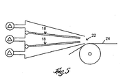
- Fig. 5 shows a head box in accordance with the invention having two blade means.
- Figure 1 shows a cross section through a
head box 10 for a paper machine. Thehead box 10 is supplied with two different streams of fibre suspension viainlet nozzles ducts 15, 16, which are arranged above each other and separated by means of a substantially horizontal blade means 18. The fibre suspension is dispensed out from thehead box 10 through anoutlet 22 onto apaper forming wire 24, where the two layers of fibre suspensions are superposed to form a layered paper web. Figure 2 shows a blade means 18 constituted by anupper sheet 26, alower sheet 28 and internal channels in the form ofparallel pipes 30 arranged between the upper and the lower sheet. Thepipes 30 are arranged side-by-side and parallel to the flow direction of the fibre suspension. Thesheets head box 10 by means of a pumping arrangement (not shown), whereby the internal channels have a pressure drop effect on the water flowing in the blade means (18). A uniform water layer is hereby formed downstream the end of the blade means 18 forming an extension of the same. The water layer prevents or reduces the occurrence of a wake downstream the edge of the blade means 18. A wake would cause development of vortices in the fibre suspension layers and thereby give rise to unwanted mixing of the layers. The blade means 18 extends substantially from the up-stream end of thehead box 10 to theoutlet 22. Thepipes 30 terminate at a distance from the outlet end of the blade means 18 as shown in figure 3, in order to achieve a uniform water flow out from the blade means 18. - An alternative embodiment of the invention is shown in figure 4, wherein the blade means 180 comprises an
upper sheet 260 and alower sheet 280, which sheets converge towards each other in the direction of the intended water flow. - In another embodiment of the invention, the blade means 18, 180 is arranged without internal channels and is instead provided with one or more pressure drop screens 38 arranged inside the blade means 18, 180 transversely to the intended direction of the water flow as shown in figure 4. The pressure drop screen preferably comprises a porous material such as a net and is arranged to span the entire width and height of a cross section of the blade means 18, 180 in order to provide a uniform water flow out from the blade means 18, 180.
- According to a preferred embodiment, the blade means 18, 180 is arranged to pivot freely around an
axis 20, which is substantially perpendicular to the direction of the intended water flow. The blade means 18, 180 can be either rigid or elastically deformable. However, the height of the water outlet from the blade means 18, 180 and thereby the height of the water layer, is kept constant. In the embodiment comprising elastically deformable blade means, this can be achieved e.g. by using a rigid material for manufacturing the outlet part of the blade means 18, 180, while the rest of the blade means is manufactured from an elastically deformable material. - The water speed can be controlled by means of adjusting the pumping pressure of the water. A
feed pipe 32, supplying water to the blade, is arranged in a position that coincides with thepivot axis 20. Thefeed pipe 32 is provided withopenings 34 through which water is supplied to the blade means 18, 180. The blade means 18, 180 is attached to thefeed pipe 32 in a rotationally fixed manner. Thefeed pipe 32 is rotationally arranged, preferably by means of aswivel connection 36 as shown in figure 3, so that the blade means 18, 180 can pivot freely. - According to an alternative embodiment, water can be fed to the blade means 18, 180 by means of a feed pipe having a single slotted, lengthwise aperture (not shown) through which water is supplied to the blade means 18, 180.
- In another embodiment of the invention, the blade means 18, 180 is elastically deformable and has a non-pivotable mounting in the
head box 10. The pressure equalization between the fibre suspension layers is hereby achieved only by deforming movements of the blade means 18, 180. Afeed pipe 32, supplying water to the blade, is arranged at the upstream end of the blade means, perpendicular to the direction of the intended water flow and provided withopenings 34 through which the water is supplied to the blade means 18, 180 - The
head box 10 can furthermore be provided with two or more blade means 18, 180, as shown in figure 5, whereby a multi-layered paper web is formed. Due to the self-adjustment of the blade means 18, 180 for pressure equalization between the fibre suspension layers, the vertical placement of the blade means 18, 180 in thehead box 10 can be either symmetric or asymmetric. - The invention is not limited to the exemplified embodiments described above. A person skilled in the art will find further applications within the scope of the invention in the accompanying claims.
Claims (21)
- A method of forming a layered fibrous web. comprising leading at least two different fibre suspensions through a head box (10), separating the fibre suspensions from each other by a blade means (18. 180), supplying the fibre suspensions to a web forming device (24) and forming a water layer having a transversely uniform flow at an outlet at the end of the blade means (18. 180), such that the water layer constitutes an extension of the blade means and thereby prevents mixing of the fibre suspensions, characterized by arranging the blade means (18, 180) to be freely movable in a substantially vertical direction in order to permit an equalization of pressure between the fibre suspension layers separated by the blade means (18, 180) and thereby reducing wake effects downstream the edge of the blade means (18, 180).
- The method according to claim 1, characterized by pumping water through the blade means (18, 180) in internal channels (30).
- The method according to claim 2, characterized by arranging the channels (30) such that they terminate at a distance from the water outlet at the end of the blade means (18, 180) in order to provide a uniform flow rate of the water coming out from the blade means.
- The method according to any of the previous claims, characterized by keeping the height of the water outlet from the blade means (18, 180), and thereby the height of the water layer, constant, and adjusting the flow rate of the water by changing the pumping pressure of the water.
- The method according to any of the previous claims, characterized by supplying water to the blade means (18, 180) by means of a feed pipe (32) arranged perpendicular to the direction of the intended water flow at an upstream end of the blade means (18, 180).
- The method according to any of the previous claims, characterized by arranging a pressure drop screen (38) inside the blade means (18, 180) transversely to the direction of the intended water flow.
- The method according to any of the previous claims, characterized by arranging the blade means (18, 180) movable in such a way that it is elastically deformable, thereby permitting the equalization of pressure between the fibre suspension layers,
- The method according to any of the previous claims, characterized by arranging the blade means (18. 180) movable in such way that it is pivotally supported at an upstream end thereof and can pivot freely around a pivot axis (20) perpendicular to the flow direction, thereby permitting equalization of pressure between the fibre suspension layers.
- The method according to claim 8, characterized by connecting the water feed pipe (32) to the blade means (18, 180) in a rotationally fixed manner such that the feed pipe (32) coincides with the pivot axis (20) of the blade means (18, 180).
- A paper machine including a head box (10) comprising at least one fibre suspension separating blade means (18, 180) provided with a water outlet, the outlet being arranged so as to form a water layer which constitutes an extension of the blade means (18, 180) and having a transversely uniform flow rate, characterized in that the blade means (18, 180) is arranged to be freely movable in a substantially vertical direction in order to permit an equalization of pressure between the fibre suspension layers separated by the blade means (18, 180) and thereby reducing wake effects downstream the edge of the blade means (18, 180).
- The paper machine according to claim 10, characterized in that the blade means is provided with internal channels (30), in which the water is pumped through the blade means (18, 180).
- The paper machine according to claim 11, characterized in that the channels (30) terminate at a distance from the water outlet at the end of the blade means (18, 180) in order to provide a uniform flow rate of the water coming out from the blade means (18, 180).
- The paper machine according to any of claims 10-12, characterized in that at least one pressure drop screen (38) is arranged inside the blade means (18, 180) transversely to the direction of the intended water flow.
- The paper machine according to claim 13, characterized in that the pressure drop screen (38) comprises a porous material.
- The paper machine according to any of claims 10-14, characterized in that the height of the water outlet from the blade means (18, 180), and thereby the height of the water layer, is constant, and that the flow rate of the water is adjusted by changing the pumping pressure of the water.
- The paper machine according to any of claims 10-15, characterized in that a feed pipe (32) that supplies water to the blade means (18, 180) is arranged at an upstream end of the blade means, perpendicular to the direction of the intended water flow.
- The paper machine according to any of claims 10-16, characterized in that the blade means (18, 180) is elastically deformable, thereby permitting equalization of pressure between the fibre suspension layers.
- The paper machine according to any of claims 10-17, characterized in that the blade means (18, 180) is pivotally supported at an upstream end of the blade means (18, 180) and can pivot freely around a pivot axis (20) perpendicular to the direction of the intended water flow, thereby permitting equalization of pressure between the fibre suspension layers.
- The paper machine according to claim 18, characterized in that the water feed pipe (32) is connected to the blade means (18. 180) in a rotationally fixed manner and in that the feed pipe (32) coincides with the pivot axis (20) of the blade means (18, 180).
- The paper machine according to any of claims 10-19, characterized in that the blade means (18) comprises a pair of parallel mutually spaced sheets (26, 28).
- The paper machine according to any of claims 10-19, characterized in that the blade means (180) comprises a pair of sheets (260, 280), which converge towards each other in the direction of the intended water flow, whereby the outlet from the blade means (180) is narrower than the inlet.
Applications Claiming Priority (3)
| Application Number | Priority Date | Filing Date | Title |
|---|---|---|---|
| SE0104073A SE520520C2 (en) | 2001-12-05 | 2001-12-05 | Method of forming a layered fibrous web and a machine for making it |
| SE0104073 | 2001-12-05 | ||
| PCT/SE2002/002217 WO2003048452A1 (en) | 2001-12-05 | 2002-12-03 | Method of forming a fibrous web and machine therefor |
Publications (2)
| Publication Number | Publication Date |
|---|---|
| EP1451407A1 EP1451407A1 (en) | 2004-09-01 |
| EP1451407B1 true EP1451407B1 (en) | 2007-05-02 |
Family
ID=20286196
Family Applications (1)
| Application Number | Title | Priority Date | Filing Date |
|---|---|---|---|
| EP02780249A Expired - Lifetime EP1451407B1 (en) | 2001-12-05 | 2002-12-03 | Method of forming a fibrous web and machine therefor |
Country Status (9)
| Country | Link |
|---|---|
| US (2) | US7429307B2 (en) |
| EP (1) | EP1451407B1 (en) |
| JP (1) | JP2005511911A (en) |
| CN (1) | CN1279241C (en) |
| AT (1) | ATE361393T1 (en) |
| AU (1) | AU2002343315A1 (en) |
| DE (1) | DE60219947T2 (en) |
| SE (1) | SE520520C2 (en) |
| WO (1) | WO2003048452A1 (en) |
Families Citing this family (17)
| Publication number | Priority date | Publication date | Assignee | Title |
|---|---|---|---|---|
| DE10327244A1 (en) * | 2003-06-17 | 2005-01-05 | Voith Paper Patent Gmbh | Papermaking forming drum has a mantle incorporating an irregular array of radial and inclined perforations |
| US20070012414A1 (en) * | 2005-07-12 | 2007-01-18 | Kajander Richard E | Multilayer nonwoven fibrous mats with good hiding properties, laminates and method |
| US20100000693A1 (en) * | 2006-10-31 | 2010-01-07 | Basf Se | Method for producing a multi layer fiber web from cellulose fibers |
| FI20075811A7 (en) * | 2007-11-14 | 2009-05-15 | Metso Paper Inc | Method for feeding thick mass to a forming bed and thick mass headbox |
| DE102008000778A1 (en) | 2008-03-20 | 2009-09-24 | Voith Patent Gmbh | Headbox for a paper or board machine |
| DE102008043145A1 (en) * | 2008-10-24 | 2010-04-29 | Voith Patent Gmbh | Two-layer casserole for a machine for producing a two-layer fibrous web |
| US9885154B2 (en) | 2009-01-28 | 2018-02-06 | Donaldson Company, Inc. | Fibrous media |
| US9303339B2 (en) | 2011-01-28 | 2016-04-05 | Donaldson Company, Inc. | Method and apparatus for forming a fibrous media |
| WO2012103280A1 (en) | 2011-01-28 | 2012-08-02 | Donaldson Company, Inc. | Method and apparatus for forming a fibrous media |
| WO2012155052A1 (en) | 2011-05-11 | 2012-11-15 | Hollingsworth & Vose Company | Systems and methods for making fiber webs |
| US8758559B2 (en) | 2011-07-27 | 2014-06-24 | Hollingsworth & Vose Company | Systems and methods for making fiber webs |
| WO2013016515A1 (en) * | 2011-07-27 | 2013-01-31 | Hollingsworth & Vose Company | Systems and methods for making fiber webs |
| SE538250C2 (en) | 2012-11-09 | 2016-04-12 | In-line production method for papermaking | |
| EP2784214B1 (en) | 2013-03-28 | 2015-09-16 | Valmet Technologies, Inc. | Feed water supply for a multi-layer headbox |
| WO2015028275A1 (en) * | 2013-08-26 | 2015-03-05 | Voith Patent Gmbh | Inclined wire former, method for the production of a wet-laid nonwoven web by means of an inclined-wire former and nonwoven web |
| US11035078B2 (en) | 2018-03-07 | 2021-06-15 | Gpcp Ip Holdings Llc | Low lint multi-ply paper products having a first stratified base sheet and a second stratified base sheet |
| CA3034832A1 (en) | 2018-03-07 | 2019-09-07 | Gpcp Ip Holdings Llc | Low lint paper products and methods of making the same |
Family Cites Families (7)
| Publication number | Priority date | Publication date | Assignee | Title |
|---|---|---|---|---|
| US3923593A (en) * | 1971-12-03 | 1975-12-02 | Beloit Corp | Multiple ply web former with divided slice chamber |
| FI58364C (en) * | 1977-07-13 | 1981-01-12 | Tampella Oy Ab | PROCEDURE FOR BANFORMING MACHINES FOR FRAMSTAELLNING AV EN TVAO- ELLER FLERSKIKTIG FIBERBANA |
| DE3112972A1 (en) * | 1981-04-01 | 1982-10-14 | J.M. Voith Gmbh, 7920 Heidenheim | MULTIPLE NOZZLE FEEDER FOR A PAPER MACHINE |
| US4376014A (en) * | 1979-04-12 | 1983-03-08 | Beloit Corporation | Headbox for forming multi-ply sheets |
| US4436587A (en) * | 1982-02-23 | 1984-03-13 | Ab Karlstads Mekaniska Werkstad | Method for producing multilayer paper |
| US5204009A (en) * | 1991-08-14 | 1993-04-20 | Kvaerner Hymac Inc. | Slurry rising apparatus and method therefor |
| DE19926804A1 (en) * | 1999-06-12 | 2000-12-14 | Voith Sulzer Papiertech Patent | Headbox |
-
2001
- 2001-12-05 SE SE0104073A patent/SE520520C2/en not_active IP Right Cessation
-
2002
- 2002-12-03 AT AT02780249T patent/ATE361393T1/en active
- 2002-12-03 AU AU2002343315A patent/AU2002343315A1/en not_active Abandoned
- 2002-12-03 CN CN02823435.9A patent/CN1279241C/en not_active Expired - Fee Related
- 2002-12-03 JP JP2003549626A patent/JP2005511911A/en active Pending
- 2002-12-03 WO PCT/SE2002/002217 patent/WO2003048452A1/en not_active Ceased
- 2002-12-03 DE DE60219947T patent/DE60219947T2/en not_active Expired - Lifetime
- 2002-12-03 EP EP02780249A patent/EP1451407B1/en not_active Expired - Lifetime
- 2002-12-03 US US10/497,419 patent/US7429307B2/en not_active Expired - Fee Related
-
2008
- 2008-08-08 US US12/221,958 patent/US20090020251A1/en not_active Abandoned
Also Published As
| Publication number | Publication date |
|---|---|
| US20050034827A1 (en) | 2005-02-17 |
| SE0104073L (en) | 2003-06-06 |
| EP1451407A1 (en) | 2004-09-01 |
| US20090020251A1 (en) | 2009-01-22 |
| CN1279241C (en) | 2006-10-11 |
| ATE361393T1 (en) | 2007-05-15 |
| WO2003048452A1 (en) | 2003-06-12 |
| CN1592806A (en) | 2005-03-09 |
| AU2002343315A1 (en) | 2003-06-17 |
| DE60219947T2 (en) | 2008-01-17 |
| US7429307B2 (en) | 2008-09-30 |
| DE60219947D1 (en) | 2007-06-14 |
| SE0104073D0 (en) | 2001-12-05 |
| JP2005511911A (en) | 2005-04-28 |
| SE520520C2 (en) | 2003-07-22 |
Similar Documents
| Publication | Publication Date | Title |
|---|---|---|
| US20090020251A1 (en) | Machine for forming a fibrous web | |
| US5645689A (en) | Multilayer headbox | |
| FI58364C (en) | PROCEDURE FOR BANFORMING MACHINES FOR FRAMSTAELLNING AV EN TVAO- ELLER FLERSKIKTIG FIBERBANA | |
| US8236137B2 (en) | Headbox for a machine for producing a fibrous web | |
| US8308909B2 (en) | Sheet forming system for a machine for producing a multilayer fibrous web | |
| JPH111884A (en) | Head box for paper-making machine | |
| JPH0770967A (en) | Method for partially controlling the flow rate of raw material pool and its raw material suspension in a papermaking machine | |
| JP3400109B2 (en) | Headbox, paper machine and manufacturing method for manufacturing multilayer paper web | |
| CA2101111A1 (en) | Multilayer head box for a paper machine or similar | |
| CN102257214A (en) | Double-layer headbox for a machine for manufacturing double-layer webs of fibrous material | |
| US5849159A (en) | Multi-layer headbox with plastic and metal divider plate | |
| JP2005511911A5 (en) | ||
| FI111278B (en) | Multilayer Inlet and Method for Setting a Relative Flow Rate of the Layers in a Multilayer Inlet | |
| CN102822416A (en) | Headbox for a machine for producing a fibrous material web | |
| GB2099031A (en) | Headbox means for paper machines | |
| CA2207971C (en) | Three-layer headbox | |
| CN1054457A (en) | Wide flow range single or multi-layer headbox | |
| FI79871B (en) | INLOPPSLAODA. | |
| GB2093879A (en) | Headboxes for paper machines | |
| EP0906467B1 (en) | Convergent flow headbox | |
| CN213772718U (en) | Pressure guniting forming device for insulating paperboards | |
| FI125186B (en) | Method and apparatus for controlling z-direction anisotropy of a fiber web made with a fiber web machine | |
| EP0971068B1 (en) | Headbox with converging side walls | |
| CN102947504A (en) | Headbox for a machine for producing a fibre-material web | |
| WO2011088888A2 (en) | Low energy head box |
Legal Events
| Date | Code | Title | Description |
|---|---|---|---|
| PUAI | Public reference made under article 153(3) epc to a published international application that has entered the european phase |
Free format text: ORIGINAL CODE: 0009012 |
|
| 17P | Request for examination filed |
Effective date: 20040517 |
|
| AK | Designated contracting states |
Kind code of ref document: A1 Designated state(s): AT BE BG CH CY CZ DE DK EE ES FI FR GB GR IE IT LI LU MC NL PT SE SI SK TR |
|
| AX | Request for extension of the european patent |
Extension state: AL LT LV MK RO |
|
| GRAP | Despatch of communication of intention to grant a patent |
Free format text: ORIGINAL CODE: EPIDOSNIGR1 |
|
| GRAS | Grant fee paid |
Free format text: ORIGINAL CODE: EPIDOSNIGR3 |
|
| GRAA | (expected) grant |
Free format text: ORIGINAL CODE: 0009210 |
|
| AK | Designated contracting states |
Kind code of ref document: B1 Designated state(s): AT BE BG CH CY CZ DE DK EE ES FI FR GB GR IE IT LI LU MC NL PT SE SI SK TR |
|
| PG25 | Lapsed in a contracting state [announced via postgrant information from national office to epo] |
Ref country code: LI Free format text: LAPSE BECAUSE OF FAILURE TO SUBMIT A TRANSLATION OF THE DESCRIPTION OR TO PAY THE FEE WITHIN THE PRESCRIBED TIME-LIMIT Effective date: 20070502 Ref country code: CH Free format text: LAPSE BECAUSE OF FAILURE TO SUBMIT A TRANSLATION OF THE DESCRIPTION OR TO PAY THE FEE WITHIN THE PRESCRIBED TIME-LIMIT Effective date: 20070502 |
|
| REG | Reference to a national code |
Ref country code: GB Ref legal event code: FG4D |
|
| REG | Reference to a national code |
Ref country code: CH Ref legal event code: EP |
|
| REG | Reference to a national code |
Ref country code: IE Ref legal event code: FG4D |
|
| REF | Corresponds to: |
Ref document number: 60219947 Country of ref document: DE Date of ref document: 20070614 Kind code of ref document: P |
|
| REG | Reference to a national code |
Ref country code: SE Ref legal event code: TRGR |
|
| PG25 | Lapsed in a contracting state [announced via postgrant information from national office to epo] |
Ref country code: ES Free format text: LAPSE BECAUSE OF FAILURE TO SUBMIT A TRANSLATION OF THE DESCRIPTION OR TO PAY THE FEE WITHIN THE PRESCRIBED TIME-LIMIT Effective date: 20070813 |
|
| NLV1 | Nl: lapsed or annulled due to failure to fulfill the requirements of art. 29p and 29m of the patents act | ||
| REG | Reference to a national code |
Ref country code: CH Ref legal event code: PL |
|
| EN | Fr: translation not filed | ||
| PG25 | Lapsed in a contracting state [announced via postgrant information from national office to epo] |
Ref country code: BE Free format text: LAPSE BECAUSE OF FAILURE TO SUBMIT A TRANSLATION OF THE DESCRIPTION OR TO PAY THE FEE WITHIN THE PRESCRIBED TIME-LIMIT Effective date: 20070502 |
|
| PG25 | Lapsed in a contracting state [announced via postgrant information from national office to epo] |
Ref country code: SI Free format text: LAPSE BECAUSE OF FAILURE TO SUBMIT A TRANSLATION OF THE DESCRIPTION OR TO PAY THE FEE WITHIN THE PRESCRIBED TIME-LIMIT Effective date: 20070502 Ref country code: CZ Free format text: LAPSE BECAUSE OF FAILURE TO SUBMIT A TRANSLATION OF THE DESCRIPTION OR TO PAY THE FEE WITHIN THE PRESCRIBED TIME-LIMIT Effective date: 20070502 Ref country code: PT Free format text: LAPSE BECAUSE OF FAILURE TO SUBMIT A TRANSLATION OF THE DESCRIPTION OR TO PAY THE FEE WITHIN THE PRESCRIBED TIME-LIMIT Effective date: 20071002 Ref country code: DK Free format text: LAPSE BECAUSE OF FAILURE TO SUBMIT A TRANSLATION OF THE DESCRIPTION OR TO PAY THE FEE WITHIN THE PRESCRIBED TIME-LIMIT Effective date: 20070502 Ref country code: BG Free format text: LAPSE BECAUSE OF FAILURE TO SUBMIT A TRANSLATION OF THE DESCRIPTION OR TO PAY THE FEE WITHIN THE PRESCRIBED TIME-LIMIT Effective date: 20070802 Ref country code: NL Free format text: LAPSE BECAUSE OF FAILURE TO SUBMIT A TRANSLATION OF THE DESCRIPTION OR TO PAY THE FEE WITHIN THE PRESCRIBED TIME-LIMIT Effective date: 20070502 |
|
| PG25 | Lapsed in a contracting state [announced via postgrant information from national office to epo] |
Ref country code: SK Free format text: LAPSE BECAUSE OF FAILURE TO SUBMIT A TRANSLATION OF THE DESCRIPTION OR TO PAY THE FEE WITHIN THE PRESCRIBED TIME-LIMIT Effective date: 20070502 |
|
| PLBE | No opposition filed within time limit |
Free format text: ORIGINAL CODE: 0009261 |
|
| STAA | Information on the status of an ep patent application or granted ep patent |
Free format text: STATUS: NO OPPOSITION FILED WITHIN TIME LIMIT |
|
| 26N | No opposition filed |
Effective date: 20080205 |
|
| PG25 | Lapsed in a contracting state [announced via postgrant information from national office to epo] |
Ref country code: GR Free format text: LAPSE BECAUSE OF FAILURE TO SUBMIT A TRANSLATION OF THE DESCRIPTION OR TO PAY THE FEE WITHIN THE PRESCRIBED TIME-LIMIT Effective date: 20070803 Ref country code: FR Free format text: LAPSE BECAUSE OF FAILURE TO SUBMIT A TRANSLATION OF THE DESCRIPTION OR TO PAY THE FEE WITHIN THE PRESCRIBED TIME-LIMIT Effective date: 20071228 |
|
| PG25 | Lapsed in a contracting state [announced via postgrant information from national office to epo] |
Ref country code: MC Free format text: LAPSE BECAUSE OF NON-PAYMENT OF DUE FEES Effective date: 20071231 |
|
| GBPC | Gb: european patent ceased through non-payment of renewal fee |
Effective date: 20071203 |
|
| PG25 | Lapsed in a contracting state [announced via postgrant information from national office to epo] |
Ref country code: IE Free format text: LAPSE BECAUSE OF NON-PAYMENT OF DUE FEES Effective date: 20071203 |
|
| PG25 | Lapsed in a contracting state [announced via postgrant information from national office to epo] |
Ref country code: FR Free format text: LAPSE BECAUSE OF FAILURE TO SUBMIT A TRANSLATION OF THE DESCRIPTION OR TO PAY THE FEE WITHIN THE PRESCRIBED TIME-LIMIT Effective date: 20070502 |
|
| PG25 | Lapsed in a contracting state [announced via postgrant information from national office to epo] |
Ref country code: GB Free format text: LAPSE BECAUSE OF NON-PAYMENT OF DUE FEES Effective date: 20071203 |
|
| PG25 | Lapsed in a contracting state [announced via postgrant information from national office to epo] |
Ref country code: EE Free format text: LAPSE BECAUSE OF FAILURE TO SUBMIT A TRANSLATION OF THE DESCRIPTION OR TO PAY THE FEE WITHIN THE PRESCRIBED TIME-LIMIT Effective date: 20070502 |
|
| PG25 | Lapsed in a contracting state [announced via postgrant information from national office to epo] |
Ref country code: CY Free format text: LAPSE BECAUSE OF FAILURE TO SUBMIT A TRANSLATION OF THE DESCRIPTION OR TO PAY THE FEE WITHIN THE PRESCRIBED TIME-LIMIT Effective date: 20070502 |
|
| PG25 | Lapsed in a contracting state [announced via postgrant information from national office to epo] |
Ref country code: LU Free format text: LAPSE BECAUSE OF NON-PAYMENT OF DUE FEES Effective date: 20071203 |
|
| PG25 | Lapsed in a contracting state [announced via postgrant information from national office to epo] |
Ref country code: TR Free format text: LAPSE BECAUSE OF FAILURE TO SUBMIT A TRANSLATION OF THE DESCRIPTION OR TO PAY THE FEE WITHIN THE PRESCRIBED TIME-LIMIT Effective date: 20070502 |
|
| PGFP | Annual fee paid to national office [announced via postgrant information from national office to epo] |
Ref country code: DE Payment date: 20171129 Year of fee payment: 16 Ref country code: FI Payment date: 20171211 Year of fee payment: 16 |
|
| PGFP | Annual fee paid to national office [announced via postgrant information from national office to epo] |
Ref country code: AT Payment date: 20171128 Year of fee payment: 16 Ref country code: SE Payment date: 20171213 Year of fee payment: 16 |
|
| PGFP | Annual fee paid to national office [announced via postgrant information from national office to epo] |
Ref country code: IT Payment date: 20171221 Year of fee payment: 16 |
|
| REG | Reference to a national code |
Ref country code: DE Ref legal event code: R119 Ref document number: 60219947 Country of ref document: DE |
|
| REG | Reference to a national code |
Ref country code: SE Ref legal event code: EUG |
|
| PG25 | Lapsed in a contracting state [announced via postgrant information from national office to epo] |
Ref country code: FI Free format text: LAPSE BECAUSE OF NON-PAYMENT OF DUE FEES Effective date: 20181203 Ref country code: SE Free format text: LAPSE BECAUSE OF NON-PAYMENT OF DUE FEES Effective date: 20181204 |
|
| REG | Reference to a national code |
Ref country code: AT Ref legal event code: MM01 Ref document number: 361393 Country of ref document: AT Kind code of ref document: T Effective date: 20181203 |
|
| PG25 | Lapsed in a contracting state [announced via postgrant information from national office to epo] |
Ref country code: DE Free format text: LAPSE BECAUSE OF NON-PAYMENT OF DUE FEES Effective date: 20190702 Ref country code: IT Free format text: LAPSE BECAUSE OF NON-PAYMENT OF DUE FEES Effective date: 20181203 |
|
| PG25 | Lapsed in a contracting state [announced via postgrant information from national office to epo] |
Ref country code: AT Free format text: LAPSE BECAUSE OF NON-PAYMENT OF DUE FEES Effective date: 20181203 |