EP1451039B1 - Coupling device for a load carrier - Google Patents
Coupling device for a load carrier Download PDFInfo
- Publication number
- EP1451039B1 EP1451039B1 EP02778148A EP02778148A EP1451039B1 EP 1451039 B1 EP1451039 B1 EP 1451039B1 EP 02778148 A EP02778148 A EP 02778148A EP 02778148 A EP02778148 A EP 02778148A EP 1451039 B1 EP1451039 B1 EP 1451039B1
- Authority
- EP
- European Patent Office
- Prior art keywords
- shaft
- sleeve
- lever link
- coupling device
- pin
- Prior art date
- Legal status (The legal status is an assumption and is not a legal conclusion. Google has not performed a legal analysis and makes no representation as to the accuracy of the status listed.)
- Expired - Lifetime
Links
- 230000008878 coupling Effects 0.000 title claims description 36
- 238000010168 coupling process Methods 0.000 title claims description 36
- 238000005859 coupling reaction Methods 0.000 title claims description 36
- 230000000717 retained effect Effects 0.000 description 1
Images


Classifications
-
- B—PERFORMING OPERATIONS; TRANSPORTING
- B60—VEHICLES IN GENERAL
- B60R—VEHICLES, VEHICLE FITTINGS, OR VEHICLE PARTS, NOT OTHERWISE PROVIDED FOR
- B60R9/00—Supplementary fittings on vehicle exterior for carrying loads, e.g. luggage, sports gear or the like
- B60R9/06—Supplementary fittings on vehicle exterior for carrying loads, e.g. luggage, sports gear or the like at vehicle front or rear
Definitions
- the present invention relates to a coupling device, for coupling a load carrier to a vehicle, preferably to the rear section of the vehicle.
- the coupling device comprises a sleeve, which is mounted on the vehicle, and a shaft, which is mounted on the load carrier, and the coupling is realized in that the shaft is mounted into the sleeve, whereupon the shaft is secured in the sleeve by means of a securing device.
- Coupling devices of the described type are commonly seen. They generally appear as so-called “hitch mounts” or “hitch posts,” primarily on the American market, and there preferably on vehicles such as smaller platform-equipped vehicles, delivery vans and similar vehicles. These devices preferably comprise a sleeve of square material, which is secured to the vehicle, and a shaft consisting of square material, which is secured to the load carrier.
- the securing device usually consists of a pin that is introduced through holes in the sleeve and shaft, which holes line up with one another when the shaft is mounted in the sleeve.
- WO 94/055266 which discloses the features of the preamble of claims 1 and 6 a load carrying arrangement is disclosed in which a connecting shaft is inserted into a recess in a vehicle's coachwork and retained by clamping a hooked arm onto a pin protruding into the recess.
- the invention now proposed overcomes the aforementioned disadvantages by means of a coupling device of the type described above, characterized in that the securing device is arranged on the shaft.
- the securing device consists of a lever link which, at a first end, is pivotably arranged on the shaft at the end of the shaft that is mounted to the sleeve and, at a second end, in connection by means of a tension mechanism with the shaft, by means of which tension mechanism the lever link can be pivoted in a direction away from the shaft, whereupon the lever link and the shaft are brought into secure clamping engagement with the sleeve when the shaft is mounted to the sleeve.
- the sleeve has a pin that extends inside the sleeve between the inner walls of the sleeve and the lever link has a notch that engages with the pin in form-locking fashion, whereupon the secure clamping engagement occurs between the inner walls of the sleeve and the shaft respectively between said pin and notch.
- the lever link is acted upon by an elastic element in a direction away from the shaft, whereupon the lever link is pushed against the pin when the shaft is mounted to the sleeve, and whereupon the notch in the lever link snaps into contact with the pin when the shaft is introduced into the sleeve.
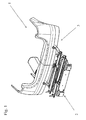
- Figure 1 is a schematic view of a rear section 1 of a vehicle.
- a load carrier 2 is coupled to the rear section by means of coupling devices 3.
- Figure 2 show that the coupling device 3 comprises a sleeve 4, a shaft 5 and a securing device 6.
- a mounting plate 7 is arranged on the sleeve 4 and the mounting plate joins the sleeve to the vehicle (not shown in the figure).
- Figure 3 shows that a first end 8 of the shaft 5 is mounted to the sleeve 4, the end 8 is inserted into the sleeve 4.
- a second end 9 of the shaft 5 is joined to the load carrier 2 (not shown in the figure).
- the securing device 6 is described in greater detail below with reference to figures 6 - 8.
- the securing device comprises a lever link 10 which, at a first end 11, is pivotably connected by means of a pivot axes 12 to the first end 8 of the shaft 5.
- the lever link 10 extends along the shaft 5 and has at its second end 13 a tension mechanism 14, by means of which the lever link can be pivoted around the pivot axes 12 away from the shaft 5 in the direction indicated by the arrow P.
- the tension mechanism comprises a nut 15 which is fixedly connected to the lever link in a known manner.
- a screw 16 cooperates with the nut 15, which screw 16 is equipped with a knob 17.
- the screw 16 is threaded into the nut 15, and the screw 16 is in abutment with the shaft 5 at the end 18 of the screw opposite to the knob.
- the elastic element 19 is connected in a known manner at a first end 20 to the lever link 10, and at a second end 21 in abutment with the shaft 5.
- the lever link is depicted with a U-shaped cross-section and, as shown, the lever link straddles the shaft.
- This shape is of value per se, in that the lever link is thereby given guidance in relation to the shaft, although this shape is of no importance to the function of the invention, and the lever link may exhibit any cross-section whatsoever that is sufficiently strong to be able to function satisfactorily.
- the sleeve 4 has a pin 22 that extends transversely in the sleeve, while the lever link 10 has a notch 23.
- the function of the pin and the notch will be described below.
- Figure 10 shows a coupling device according to the present invention that lacks the pin 22 and, in this arrangement, the connection is realized in that the lever link 10 and the shaft 5 are pushed against the inner walls 24 of the sleeve 4 to produce a fixed and secure connection.
- the sleeve part has been depicted in the description above as a square tube, and the shaft part as a round tube. It will be apparent to one skilled in the art that both the sleeve part and the shaft part can exhibit any cross-section whatsoever, assuming that the shaft part can be inserted into the sleeve part. It is also apparent to the one skilled in the art, with regards to the designs where the pin 22 engages with the notch 23, that the wall parts 26 and 27, fig.9, of the sleeve 4 can be omitted.
Landscapes
- Engineering & Computer Science (AREA)
- Mechanical Engineering (AREA)
- Fittings On The Vehicle Exterior For Carrying Loads, And Devices For Holding Or Mounting Articles (AREA)
- Pivots And Pivotal Connections (AREA)
- Mutual Connection Of Rods And Tubes (AREA)
Description
- The present invention relates to a coupling device, for coupling a load carrier to a vehicle, preferably to the rear section of the vehicle. The coupling device comprises a sleeve, which is mounted on the vehicle, and a shaft, which is mounted on the load carrier, and the coupling is realized in that the shaft is mounted into the sleeve, whereupon the shaft is secured in the sleeve by means of a securing device.
- Coupling devices of the described type are commonly seen. They generally appear as so-called "hitch mounts" or "hitch posts," primarily on the American market, and there preferably on vehicles such as smaller platform-equipped vehicles, delivery vans and similar vehicles. These devices preferably comprise a sleeve of square material, which is secured to the vehicle, and a shaft consisting of square material, which is secured to the load carrier. The securing device usually consists of a pin that is introduced through holes in the sleeve and shaft, which holes line up with one another when the shaft is mounted in the sleeve. The disadvantage with such earlier hitch devices is that the play that must be present to enable the shaft to be introduced into the sleeve is not taken up by the pin, which means that the load carrier can vibrate forcefully when the vehicle is operated on roads with uneven pavement. These vibrations entail a risk that the cargo carried by the load carrier may be damaged or, in the worst case, come free from the load carrier entirely. Another disadvantage of such earlier devices is that the pin must be inserted into the sleeve from the outside, which means that the sleeve must be readily accessible, making it difficult to conceal, which is perceived on modern cars as a design problem, insofar as the presence of tubes or tow hooks that break the design silhouette of the vehicle is often perceived negatively. Yet another disadvantage is inherent in the adjustment of the shaft and sleeve that must be done in order for the holes realized therein to line up with one another could often be difficult to accomplish, particular when mounting occurs in the dark.
- A desire thus exists to provide a coupling device of the afore described type that overcomes the vibration problems that encumber earlier devices, that solves these problems without breaking the silhouette of the vehicle with protruding elements, and is designed so that no adjustment of the shaft relative to the sleeve needs to be carried out.
- In WO 94/05526, which discloses the features of the preamble of
claims 1 and 6 a load carrying arrangement is disclosed in which a connecting shaft is inserted into a recess in a vehicle's coachwork and retained by clamping a hooked arm onto a pin protruding into the recess. - The invention now proposed overcomes the aforementioned disadvantages by means of a coupling device of the type described above, characterized in that the securing device is arranged on the shaft.
- In a particular embodiment the securing device consists of a lever link which, at a first end, is pivotably arranged on the shaft at the end of the shaft that is mounted to the sleeve and, at a second end, in connection by means of a tension mechanism with the shaft, by means of which tension mechanism the lever link can be pivoted in a direction away from the shaft, whereupon the lever link and the shaft are brought into secure clamping engagement with the sleeve when the shaft is mounted to the sleeve.
- In another particular embodiment the sleeve has a pin that extends inside the sleeve between the inner walls of the sleeve and the lever link has a notch that engages with the pin in form-locking fashion, whereupon the secure clamping engagement occurs between the inner walls of the sleeve and the shaft respectively between said pin and notch.
- In yet another embodiment, the lever link is acted upon by an elastic element in a direction away from the shaft, whereupon the lever link is pushed against the pin when the shaft is mounted to the sleeve, and whereupon the notch in the lever link snaps into contact with the pin when the shaft is introduced into the sleeve.
- In a further embodiment is the circumference of the sleeve confined of the pin and the sleeve walls
- The invention is described below with reference to the accompanying figures, wherein:
- Figure 1 is a partial view of the rear section of a vehicle to which a load carrier is coupled;
- Figure 2 is a plan view of a coupling device according to the invention;
- Figure 3 is a side view of a coupling device according to the invention;
- Figures 4 - 6 are side views in partial section of a coupling device according to the invention in three different coupling configurations;
- Figure 7 is a view of a coupling device according to the invention as viewed from the side, facing out from the rear section of the vehicle;
- Figure 8 is a sectional view of the section A-A in Figure 8;
- figure 9 is a sectional view of the section B-B in Figure 3 and
- Figure 10 is a view, corresponding to Figure 6, of a somewhat modified coupling device according to the invention.
- Figure 1 is a schematic view of a
rear section 1 of a vehicle. Aload carrier 2 is coupled to the rear section by means ofcoupling devices 3. Figure 2 show that thecoupling device 3 comprises asleeve 4, ashaft 5 and asecuring device 6. Amounting plate 7 is arranged on thesleeve 4 and the mounting plate joins the sleeve to the vehicle (not shown in the figure). - Figure 3 shows that a
first end 8 of theshaft 5 is mounted to thesleeve 4, theend 8 is inserted into thesleeve 4. A second end 9 of theshaft 5 is joined to the load carrier 2 (not shown in the figure). - The
securing device 6 is described in greater detail below with reference to figures 6 - 8. The securing device comprises alever link 10 which, at afirst end 11, is pivotably connected by means of apivot axes 12 to thefirst end 8 of theshaft 5. Thelever link 10 extends along theshaft 5 and has at its second end 13 atension mechanism 14, by means of which the lever link can be pivoted around thepivot axes 12 away from theshaft 5 in the direction indicated by the arrow P. - The tension mechanism comprises a
nut 15 which is fixedly connected to the lever link in a known manner. Ascrew 16 cooperates with thenut 15, whichscrew 16 is equipped with aknob 17. Thescrew 16 is threaded into thenut 15, and thescrew 16 is in abutment with theshaft 5 at theend 18 of the screw opposite to the knob. Anelastic element 19, which has the form of a helical spring in the figures, is arranged around thescrew 16. Theelastic element 19 is connected in a known manner at afirst end 20 to thelever link 10, and at asecond end 21 in abutment with theshaft 5. It will be apparent to one skilled in the art that theelastic element 19 acts upon thelever link 10 in the direction of the arrow P, and that the lever link can be pushed down toward theshaft 5, see Figure 5, against the force exerted by the elastic element when thescrew 16 is screwed up in the direction of the arrow P and thus will not abut theshaft 5. - The lever link is depicted with a U-shaped cross-section and, as shown, the lever link straddles the shaft. This shape is of value per se, in that the lever link is thereby given guidance in relation to the shaft, although this shape is of no importance to the function of the invention, and the lever link may exhibit any cross-section whatsoever that is sufficiently strong to be able to function satisfactorily.
- As shown in figures 4 and 9, the
sleeve 4 has apin 22 that extends transversely in the sleeve, while thelever link 10 has anotch 23. The function of the pin and the notch will be described below. - The function of the coupling device will be described below with reference to figure 4 - 9. When a coupling device according to the present invention is to be coupled together, the
first end 8 of theshaft 5 is mounted in thesleeve 4 in the manner shown in Figure 4. Theend 8 is equipped with a bushing 24, but this bushing has no importance to the invention and will consequently not be described further. In the position shown in Figure 4, thescrew 16 has been screwed up to a position such that it is no longer in contact with the shaft 5 (not shown in the figures). Thelever link 10 is held in its position by theelastic element 19. Theshaft 5 is then moved in the direction of the arrow F to the position shown in Figure 5. In this position thelever link 10 meets thepin 22 and, because thescrew 16 has been screwed up, thelink 10 will be pushed downward against theshaft 5 towards the force exerted by the elastic element 19 (not visible in the figure), which is working to press thelink 10 in the direction of the arrow P. Theshaft part 5 is then mowed further into thesleeve 4 in the direction of the arrow F to the position shown in Figure 6 and, in this position, the elastic element 19 (not visible in the figure) snaps thenotch 23 into abutment about thepin 22. An indication that theshaft 5 has been mowed to its proper position in thesleeve 4 is thus obtained. In this position thescrew 16 is tightened and thelever link 10 is mowed in the direction of the arrow P, whereupon theshaft 5 is pushed against theinner walls 25 of thesleeve 4, while thenotch 23 in thelever link 10 is simultaneously pushed against thepin 22 as shown in Figure 9. A stable, secure and non-slipping connection can be achieved between the sleeve and theshaft 5 by forcefully tightening thescrew 16, while thepin 22 and thenotch 23 simultaneously ensure that the shaft cannot be displaced from thesleeve 4. - Figure 10 shows a coupling device according to the present invention that lacks the
pin 22 and, in this arrangement, the connection is realized in that thelever link 10 and theshaft 5 are pushed against theinner walls 24 of thesleeve 4 to produce a fixed and secure connection. - The sleeve part has been depicted in the description above as a square tube, and the shaft part as a round tube. It will be apparent to one skilled in the art that both the sleeve part and the shaft part can exhibit any cross-section whatsoever, assuming that the shaft part can be inserted into the sleeve part. It is also apparent to the one skilled in the art, with regards to the designs where the
pin 22 engages with thenotch 23, that thewall parts sleeve 4 can be omitted. Thereby is the circumference of the sleeve confined of the pin and the remaining parts of thesleeve walls 24 Furthermore, theelastic element 19 has been depicted as a helical spring, but it will be apparent to one skilled in the art that any other elastic element that provides the described function could be used. The invention is thus not limited to the foregoing description, but rather solely by the claims that follow.
Claims (10)
- A coupling device (3) for coupling a load carrier (2) to a vehicle, preferably to the rear section (1) of the vehicle, the coupling device comprising a sleeve (4) which is mounted on the rear section of the vehicle and a shaft (5) which is mounted on the load carrier (2), the coupling being realized in that the shaft (5) is mounted into the sleeve (4), whereupon the shaft (5) is secured to the sleeve by means of a securing device (6) which is arranged on the shaft (5), the securing device (6) comprises a lever link (10) that is, at a first end (11), pivotably arranged on the shaft (5) at its first end (8) by means of a pivot axes (12), which first end (8) is mounted to the sleeve (4), characterized in that the securing device at a second end (13), is in connection by means of a tension mechanism (14) with the shaft (5), the lever link (10) being pivotable by the tension mechanism in a direction (P) away from the shaft (5), whereupon the lever link (10) and the shaft (5) are brought into secure clamping engagement with the inner walls (25) of the sleeve (4) when the shaft (5) is mounted to the sleeve (4).
- A coupling device according to claim 1, characterized in that the sleeve (4) comprises a pin (22) that extends transversely in the sleeve (4) and in that the lever link (10) has a notch (23), the lever link (10) being pivotable by the tension mechanism (14) in a direction (P) away from the shaft such that the notch (23) is brought into engagement with the pin (22), whereby the shaft is brought into secure clamping connection with the sleeve (4) via the engagement between the shaft (5) and the inner walls (25) of the sleeve and respectively between the pin (22) and the notch (23).
- A coupling device according to claim 2, characterized in that the lever link (10) is acted upon by an elastic element (19), which pushes the lever link (10) in a direction (P) away from the shaft, whereupon the lever link is pushed against the pin (22) when the shaft (5) is mounted into the sleeve (4) in a direction (F), whereupon the notch (23) is snapped around the pin (22) when the shaft (5) is moved to a position in which the notch encounters the pin.
- A coupling device according to claim 2 or 3, characterized in that the sleeve (4) circumference is confined of the sleeve walls (24) and the pin (22).
- A coupling device according to any preceding claim, characterized in that the sleeve is a square tube and the shaft is a round tube.
- A coupling device for coupling a load carrier (2) to the rear section of a vehicle, the coupling device comprising a shaft (5) which is mounted on the load carrier (2) and coupling to the vehicle being realized in that in use the shaft (5) is mounted into a sleeve (4) on the vehicle, whereupon the shaft (5) is secured to the sleeve by means of a securing device (6) which is arranged on the shaft (5), the securing device (6) comprises a lever link (10) that is, at a first end (11), pivotably arranged on the shaft (5) at its first end (8) by means of a pivot axes (12), which first end (8) is mounted to the sleeve (4) characterized in that the securing device at a second end (13), is in connection by means of a tension mechanism (14) with the shaft (5), the lever link (10) being pivotable by the tension mechanism in a direction (P) away from the shaft (5), whereupon the lever link (10) and the shaft (5) are brought into secure clamping engagement with the inner walls (25) of the sleeve (4) when the shaft (5) is mounted to the sleeve (4).
- A coupling device according to any preceding claim, characterized in that the tension mechanism (14) comprises a nut (15) fixedly connected to the lever link (10), a screw (16) that co-operates with the nut (15), which screw (16) is equipped with a knob (17), the screw being threaded into the nut and being in abutment with the shaft (5) at the end (18) of the screw opposite the knob.
- A coupling device according to claim 7, characterized in that said coupling device further comprises an elastic element (19) that is arranged around the screw (16) and is connected at a first end (20) to the lever link (10) and at a second end is in abutment with the shaft (5).
- A coupling device according to claim 8, characterized in that, when the screw (16) is screwed up, the lever link (10) can be pushed down towards the shaft (5) against the force exerted by the elastic element (19).
- A coupling device according to any preceding claim, characterized in that the lever link (10) has a U-shaped cross section.
Applications Claiming Priority (3)
| Application Number | Priority Date | Filing Date | Title |
|---|---|---|---|
| SE0103674 | 2001-11-06 | ||
| SE0103674A SE520614C2 (en) | 2001-11-06 | 2001-11-06 | Coupling device for a load carrier |
| PCT/SE2002/001867 WO2003039912A1 (en) | 2001-11-06 | 2002-10-15 | Coupling device for a load carrier |
Publications (2)
| Publication Number | Publication Date |
|---|---|
| EP1451039A1 EP1451039A1 (en) | 2004-09-01 |
| EP1451039B1 true EP1451039B1 (en) | 2006-07-26 |
Family
ID=20285875
Family Applications (1)
| Application Number | Title | Priority Date | Filing Date |
|---|---|---|---|
| EP02778148A Expired - Lifetime EP1451039B1 (en) | 2001-11-06 | 2002-10-15 | Coupling device for a load carrier |
Country Status (4)
| Country | Link |
|---|---|
| EP (1) | EP1451039B1 (en) |
| DE (1) | DE60213458T2 (en) |
| SE (1) | SE520614C2 (en) |
| WO (1) | WO2003039912A1 (en) |
Families Citing this family (5)
| Publication number | Priority date | Publication date | Assignee | Title |
|---|---|---|---|---|
| FR2867120B1 (en) | 2004-03-02 | 2006-04-28 | Renault Sas | CARRIER FOR EQUIPPING THE REAR OF A MOTOR VEHICLE |
| DE102004033809B4 (en) * | 2004-07-12 | 2016-05-12 | Volkswagen Ag | Recording device for a vehicle |
| EP2428405B1 (en) * | 2010-09-13 | 2015-10-07 | WESTFALIA - Automotive GmbH | Coupling for a load carrier system with a tensioning member |
| DE102014017019A1 (en) * | 2014-11-19 | 2016-05-19 | Westfalia-Automotive Gmbh | Porters clutch |
| FR3138796B1 (en) * | 2022-08-10 | 2024-06-28 | Renault Sas | Load carrier of a motor vehicle |
Family Cites Families (2)
| Publication number | Priority date | Publication date | Assignee | Title |
|---|---|---|---|---|
| CA2143282A1 (en) * | 1992-09-08 | 1994-03-17 | Eberhard Tittel | Load carrying arrangement for attachment of a load carrier to the rear of a motor vehicle |
| SE9904409L (en) * | 1999-12-03 | 2001-06-04 | Saab Automobile | Motor vehicles with fastening device for load carriers, as well as a cargo carrier |
-
2001
- 2001-11-06 SE SE0103674A patent/SE520614C2/en not_active IP Right Cessation
-
2002
- 2002-10-15 WO PCT/SE2002/001867 patent/WO2003039912A1/en not_active Ceased
- 2002-10-15 EP EP02778148A patent/EP1451039B1/en not_active Expired - Lifetime
- 2002-10-15 DE DE60213458T patent/DE60213458T2/en not_active Expired - Lifetime
Also Published As
| Publication number | Publication date |
|---|---|
| DE60213458T2 (en) | 2007-03-15 |
| SE0103674L (en) | 2003-05-07 |
| EP1451039A1 (en) | 2004-09-01 |
| SE520614C2 (en) | 2003-07-29 |
| SE0103674D0 (en) | 2001-11-06 |
| DE60213458D1 (en) | 2006-09-07 |
| WO2003039912A1 (en) | 2003-05-15 |
Similar Documents
| Publication | Publication Date | Title |
|---|---|---|
| US5615904A (en) | Drawbar coupler for an automotive vehicle hitch rack | |
| EP2233360B2 (en) | Snap fit connection in a rear view mirror | |
| CA2131472C (en) | Receiver hitch anti-rattle device | |
| US7862066B2 (en) | 3 way ATV/UTV tractor receiver hitch | |
| US5832572A (en) | Safety hook and latch plate therefor | |
| CA2728971C (en) | Safety brake system for trailers | |
| US7044493B1 (en) | Trailer hitch tow bar assembly | |
| CA2191150A1 (en) | Trailer hitch | |
| EP1451039A1 (en) | Coupling device for a load carrier | |
| JP2004338666A (en) | Vehicle traction device | |
| US20020113408A1 (en) | Bumper unit having a hitching towing arrangement and a method of making same | |
| US20030090085A1 (en) | Trailer hitch with electrical connector | |
| US6979015B1 (en) | Trailer hitch assembly and method | |
| EP1008468A3 (en) | Mounting for drawbar | |
| US6290247B1 (en) | Bicycle trailer hitch | |
| US8052172B1 (en) | Glad hand locking device | |
| US6360859B1 (en) | Device and method in braking systems for motor vehicles | |
| CN110294045A (en) | Attachment device and application thereof, the system with this attachment device and vehicle | |
| ATE196099T1 (en) | TRAILER COUPLING FOR TOY VEHICLES, ESPECIALLY TRACTOR COUPLING | |
| CA2287539A1 (en) | Lower steering arm assembly for an attaching device of a tractor | |
| KR100835599B1 (en) | Detachable trailer towing | |
| WO2006126818A1 (en) | Fixed cellular phone for vehicle | |
| US20080008571A1 (en) | Wheel lift lock | |
| US20120050900A1 (en) | Trailer hitch mirror | |
| CA2287516A1 (en) | Lower steering arm assembly for an attaching device of a tractor |
Legal Events
| Date | Code | Title | Description |
|---|---|---|---|
| PUAI | Public reference made under article 153(3) epc to a published international application that has entered the european phase |
Free format text: ORIGINAL CODE: 0009012 |
|
| 17P | Request for examination filed |
Effective date: 20040518 |
|
| AK | Designated contracting states |
Kind code of ref document: A1 Designated state(s): AT BE BG CH CY CZ DE DK EE ES FI FR GB GR IE IT LI LU MC NL PT SE SK TR |
|
| AX | Request for extension of the european patent |
Extension state: AL LT LV MK RO SI |
|
| 17Q | First examination report despatched |
Effective date: 20050217 |
|
| RAP1 | Party data changed (applicant data changed or rights of an application transferred) |
Owner name: THULE SWEDEN AB Owner name: RENAULT SAS |
|
| GRAP | Despatch of communication of intention to grant a patent |
Free format text: ORIGINAL CODE: EPIDOSNIGR1 |
|
| GRAS | Grant fee paid |
Free format text: ORIGINAL CODE: EPIDOSNIGR3 |
|
| RIN1 | Information on inventor provided before grant (corrected) |
Inventor name: PERSON, JOAKIM Inventor name: VEUILLOT, OLIVIER Inventor name: ODIN, HANS Inventor name: PREMARTIN, ARNAUD |
|
| GRAA | (expected) grant |
Free format text: ORIGINAL CODE: 0009210 |
|
| AK | Designated contracting states |
Kind code of ref document: B1 Designated state(s): BE DE FR GB |
|
| REG | Reference to a national code |
Ref country code: GB Ref legal event code: FG4D |
|
| REF | Corresponds to: |
Ref document number: 60213458 Country of ref document: DE Date of ref document: 20060907 Kind code of ref document: P |
|
| REG | Reference to a national code |
Ref country code: FR Ref legal event code: RN |
|
| REG | Reference to a national code |
Ref country code: FR Ref legal event code: FC |
|
| EN | Fr: translation not filed | ||
| PLBE | No opposition filed within time limit |
Free format text: ORIGINAL CODE: 0009261 |
|
| STAA | Information on the status of an ep patent application or granted ep patent |
Free format text: STATUS: NO OPPOSITION FILED WITHIN TIME LIMIT |
|
| ET | Fr: translation filed | ||
| 26N | No opposition filed |
Effective date: 20070427 |
|
| PGFP | Annual fee paid to national office [announced via postgrant information from national office to epo] |
Ref country code: BE Payment date: 20121022 Year of fee payment: 11 |
|
| PGFP | Annual fee paid to national office [announced via postgrant information from national office to epo] |
Ref country code: GB Payment date: 20121019 Year of fee payment: 11 |
|
| BERE | Be: lapsed |
Owner name: *THULE SWEDEN A.B. Effective date: 20131031 Owner name: *RENAULT S.A.S. Effective date: 20131031 |
|
| GBPC | Gb: european patent ceased through non-payment of renewal fee |
Effective date: 20131015 |
|
| PG25 | Lapsed in a contracting state [announced via postgrant information from national office to epo] |
Ref country code: GB Free format text: LAPSE BECAUSE OF NON-PAYMENT OF DUE FEES Effective date: 20131015 |
|
| PG25 | Lapsed in a contracting state [announced via postgrant information from national office to epo] |
Ref country code: BE Free format text: LAPSE BECAUSE OF NON-PAYMENT OF DUE FEES Effective date: 20131031 |
|
| REG | Reference to a national code |
Ref country code: FR Ref legal event code: PLFP Year of fee payment: 14 |
|
| REG | Reference to a national code |
Ref country code: FR Ref legal event code: PLFP Year of fee payment: 15 |
|
| REG | Reference to a national code |
Ref country code: FR Ref legal event code: PLFP Year of fee payment: 16 |
|
| REG | Reference to a national code |
Ref country code: FR Ref legal event code: PLFP Year of fee payment: 17 |
|
| PGFP | Annual fee paid to national office [announced via postgrant information from national office to epo] |
Ref country code: DE Payment date: 20191021 Year of fee payment: 18 |
|
| PGFP | Annual fee paid to national office [announced via postgrant information from national office to epo] |
Ref country code: FR Payment date: 20191028 Year of fee payment: 18 |
|
| REG | Reference to a national code |
Ref country code: DE Ref legal event code: R119 Ref document number: 60213458 Country of ref document: DE |
|
| PG25 | Lapsed in a contracting state [announced via postgrant information from national office to epo] |
Ref country code: DE Free format text: LAPSE BECAUSE OF NON-PAYMENT OF DUE FEES Effective date: 20210501 Ref country code: FR Free format text: LAPSE BECAUSE OF NON-PAYMENT OF DUE FEES Effective date: 20201031 |
|
| P01 | Opt-out of the competence of the unified patent court (upc) registered |
Effective date: 20230528 |