EP1450522A2 - Multi-hop communication system radio control station, radio station and multi-hop communication method - Google Patents
Multi-hop communication system radio control station, radio station and multi-hop communication method Download PDFInfo
- Publication number
- EP1450522A2 EP1450522A2 EP20040003847 EP04003847A EP1450522A2 EP 1450522 A2 EP1450522 A2 EP 1450522A2 EP 20040003847 EP20040003847 EP 20040003847 EP 04003847 A EP04003847 A EP 04003847A EP 1450522 A2 EP1450522 A2 EP 1450522A2
- Authority
- EP
- European Patent Office
- Prior art keywords
- radio
- station
- control signal
- communication route
- communication
- Prior art date
- Legal status (The legal status is an assumption and is not a legal conclusion. Google has not performed a legal analysis and makes no representation as to the accuracy of the status listed.)
- Granted
Links
Images


Classifications
-
- H—ELECTRICITY
- H04—ELECTRIC COMMUNICATION TECHNIQUE
- H04W—WIRELESS COMMUNICATION NETWORKS
- H04W68/00—User notification, e.g. alerting and paging, for incoming communication, change of service or the like
-
- H—ELECTRICITY
- H04—ELECTRIC COMMUNICATION TECHNIQUE
- H04L—TRANSMISSION OF DIGITAL INFORMATION, e.g. TELEGRAPHIC COMMUNICATION
- H04L45/00—Routing or path finding of packets in data switching networks
- H04L45/302—Route determination based on requested QoS
-
- H—ELECTRICITY
- H04—ELECTRIC COMMUNICATION TECHNIQUE
- H04W—WIRELESS COMMUNICATION NETWORKS
- H04W4/00—Services specially adapted for wireless communication networks; Facilities therefor
- H04W4/24—Accounting or billing
-
- H—ELECTRICITY
- H04—ELECTRIC COMMUNICATION TECHNIQUE
- H04W—WIRELESS COMMUNICATION NETWORKS
- H04W40/00—Communication routing or communication path finding
- H04W40/02—Communication route or path selection, e.g. power-based or shortest path routing
-
- H—ELECTRICITY
- H04—ELECTRIC COMMUNICATION TECHNIQUE
- H04W—WIRELESS COMMUNICATION NETWORKS
- H04W48/00—Access restriction; Network selection; Access point selection
- H04W48/08—Access restriction or access information delivery, e.g. discovery data delivery
-
- H—ELECTRICITY
- H04—ELECTRIC COMMUNICATION TECHNIQUE
- H04W—WIRELESS COMMUNICATION NETWORKS
- H04W48/00—Access restriction; Network selection; Access point selection
- H04W48/16—Discovering, processing access restriction or access information
-
- H—ELECTRICITY
- H04—ELECTRIC COMMUNICATION TECHNIQUE
- H04W—WIRELESS COMMUNICATION NETWORKS
- H04W84/00—Network topologies
- H04W84/18—Self-organising networks, e.g. ad-hoc networks or sensor networks
-
- Y—GENERAL TAGGING OF NEW TECHNOLOGICAL DEVELOPMENTS; GENERAL TAGGING OF CROSS-SECTIONAL TECHNOLOGIES SPANNING OVER SEVERAL SECTIONS OF THE IPC; TECHNICAL SUBJECTS COVERED BY FORMER USPC CROSS-REFERENCE ART COLLECTIONS [XRACs] AND DIGESTS
- Y02—TECHNOLOGIES OR APPLICATIONS FOR MITIGATION OR ADAPTATION AGAINST CLIMATE CHANGE
- Y02D—CLIMATE CHANGE MITIGATION TECHNOLOGIES IN INFORMATION AND COMMUNICATION TECHNOLOGIES [ICT], I.E. INFORMATION AND COMMUNICATION TECHNOLOGIES AIMING AT THE REDUCTION OF THEIR OWN ENERGY USE
- Y02D30/00—Reducing energy consumption in communication networks
- Y02D30/70—Reducing energy consumption in communication networks in wireless communication networks
Definitions
- the present invention relates to a multi-hop communication system and a multi-hop communication method, which are configured by a radio control station and radio stations.
- the present invention also relates to a radio control station and a radio station used in the multi-hop communication system.
- the present invention relates to a cellular phone system, in which a radio base station acts as the radio control station, and a wireless LAN, in which an access point acts as the radio control station.
- ad hoc network In an ad hoc network, communications between two stations, which cannot directly communicate with each other, are achieved using multiple stations. The multiple stations relay signals transmitted by the origin to the destination (which is called "multi-hop connection").
- multi-hop connection As for the ad hoc network, various kinds of commutation route discovery protocols have been proposed, i.e., DSR (Direct Source Routing) and AODV (Ad hoc On demand Distance Vector).
- a centralized control station like the base station in the cellular phone system does not exist. Therefore, normally the radio station itself discovers a communication route autonomously.
- the multi-hop cellular in which a communication route from the radio station to the base station is acquired by a multi-hop connection, has also been proposed.
- the multi-hop cellar since the radio station can access to a core network via the base station, communications with the destination becomes possible if a communication route up to the base station is acquired. Therefore, probability of connection with the distant destination is higher than the ad hoc network.
- the present invention has been made in view of the above perspectives, and thus has an object of providing a multi-hop communication system, a radio control station, a radio station and a multi-hop communication method, which enables acquisition of an appropriate communication routes between the radio stations or between the radio station and the radio control station with small amount of control signals.
- a multi-hop communication system which is configured by a radio control station that is connected to a core network, and radio stations that relay an information signal transmitted by other radio stations, determines a communication route for a control signal and a communication route for an information signal by different independent processes.
- the control signal and the information signal are transmitted by the determined communication routes.
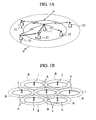
- FIG. 1A is a schematic diagram showing overall configuration of the multi-hop communication system.
- the multi-hop communication system is configured by a radio control station 1 connected to a core network, e.g., a wideband wired network, and radio stations 21, 22, 31-33 located either inside or outside of an area A that is covered by the radio control station 1.
- area A means an area, in which the radio control station 1 can directly transmits/receives an information signal with the radio stations 21, 22, 31-33.
- the information signal contains user information, e.g., data packets and voice packets.
- each area B has a shape of a ring and is overlapped with the other areas B.
- the radio stations 21, 22 are located in the area A of the radio control station 1.
- the radio stations 31-33 are located outside of the area A. Therefore, the radio stations 31-33 cannot directly transmit the information signal to the radio control station 1.
- the radio stations 31-33 are located in the area B of the radio control station 1.
- the radio stations 31-33 can transmit/receive only the control signal, i.e., a pilot signal, to the radio control station 1.
- control signal i.e., a pilot signal
- the control signal is transmitted with a lower bit rate in comparison with the information signal.
- FIG. 2A is a block diagram of the radio control station 1
- FIG. 2B is a block diagram of the radio stations 21, 22, 31-33.
- the radio control station 1 has a radio communication unit 11 which transmits/receives the information signal and the control signal using a radio communication scheme (e.g., CDMA) , a control signal TX/RX unit 12 which transmits/receives the control signal, a control signal processor 14 which generates/processes the control signal.
- a radio communication scheme e.g., CDMA
- the radio control station 1 has a communication channel controller 15 which transmits a "usage notification" indicating usage of communication channels managed by the radio control station 1 to the radio stations 21, 22, 31-33 using the control signal.
- the radio control station 1 also has a communication route determiner 17 which determines a communication route for the information signal and the control signal, an information signal TX/RX unit 13 which transmits/receives the information signal, and an information signal processor 16 which generates/processes the information signal.
- the communication route determiner 17 determines a communication route for transmission/reception of the control signal by a different independent process from the process for determination of a communication route for transmission/reception of the information signal.
- the communication route determiner 17 determines if the radio control station 1 can directly transmit/receive the information signal with the radio station based on a reception level of the control signal (e.g. , a pilot signal) received at the control signal TX/RX unit 12.
- a reception level of the control signal e.g. , a pilot signal
- transmission/reception of the control signal is performed directly with the radio station as a different independent process using the control signal TX/RX unit 12.
- the process has no relations to the processes for determination of a communication route for the information signal. It means that two different communication routes may be set between the radio control station 1 and the radio station. Such as a communication route for the control signal, of which bit rate is lower than the information signal, and a communication route for the information signal.
- the control signal of which bit rate is lower than the information signal, can cover a larger transmission area in comparison with the information signal. Therefore, the radio control station 1 and the radio station (21, 22, 31-33) can transmit/receive the control signal even if the radio control station 1 and the radio station (21, 22, 31-33) is distant, as they cannot directly transmit/receive the information signal.
- the communication route determiner 17 can estimate the distance between the radio control station 1 and the radio station according to the reception level of the control signal (e.g. , the pilot signal) transmitted by the radio station.
- the communication route determiner 17 can also determine whether transmission/reception of the information signal directly performed with the radio station.
- control signal TX/RXunit 12 can directly transmit/receive the information signal between the radio contrcl station 1 and the radio station. Further, the control signal TX/RX unit 12 can perform the multi-hop connection for transmission/reception of the information signal via a plurality of the radio stations.
- the communication route determiner 17 is located in the radio control station 1, the present invention is not limited to such embodiment.
- the communication route determiner having above described function may be located in the radio station 21, 22, 31-33 in order for the radio stations to determine the communication routes for the information signal and the control signal by a different independent processes.
- the radio stations 21, 22, 31-33 have a radio communication unit 41 which transmits/receives the information signal and the control signal using a radio communication scheme (e.g., CDMA) , a control signal TX/RX unit 42 which transmits/receives the control signal, a control signal processor 44 which generates/processes the control signal.
- a radio communication scheme e.g., CDMA
- TX/RX unit 42 which transmits/receives the control signal
- a control signal processor 44 which generates/processes the control signal.
- the radio stations 21, 22, 31-33 also have an information signal TX/RX unit 43 which transmits/receives the information signal and an information signal processor 46 which generates/processes the information signal.
- control signal processor 44 can transmit a usage inquiry for inquiring usage of the communication channel handled by the radio control station 1 through the control signal.
- the control signal processor 44 can also transmit/receive the information signal according to a usage notification that is a response to the usage inquiry.
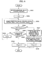
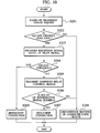
- FIG. 3 is a flowchart showing an operation of the multi-hop communication system.
- the radio station (either one of radio stations 21, 22, 31-33) transmits the usage inquiry for inquiring usage of the communication channel to the radio control station 1 without a relay by the other radio station, i.e., directly, when commencing communications via the radio control station 1.
- step S102 the radio control station 1 checks whether or not a vacant communication channel is available according to the usage inquiry transmitted in the step S101.
- the communication channel controller 15 that manages usage of the communication channel (s) handled by the radio control station 1 checks the usage of the communication channel and decides whether or not the vacant communication channel is available.
- step S103 the radio control station 1 discovers a communication route for transmission/reception of the information signal.
- step S104 the radio control station 1 commences transmission/reception of the information signal, i.e., communications with the radio station using the communication route discovered in the step S103.
- step S105 the radio control station 1 determines that communication is not possible with the radio station and then discontinues setting of the communication route to the radio station.
- the radio station (the radio stations 21, 22, 31-33) inquiries usage of the communication channel handled by the radio control station 1 before transmission/reception of the information signal. Further, the radio station determines setting of a communication route based on the availability of the vacant channel.
- FIG. 4 is a schematic diagram showing overall configuration of the multi-hop communication system according to the embodiment.
- whether or not communication is directly conducted between the radio station and the radio control station is determined based on a reception level of the control signal (e.g., a pilot signal).
- a reception level of the control signal e.g., a pilot signal
- the radio control station 1 has a radio communication unit 11 which transmits/receives the information signal and the control signal using a radio communication scheme (e. g. , CDMA) , a control signal TX/RXunit 12 which transmits/receives the control signal, a control signal processor 14 which generates/processes the control signal.
- a radio communication scheme e. g. , CDMA
- the radio control station 1 has a communication channel controller 15 which transmits a "usage notification" indicating usage of communication channels managed by the radio control station 1 to the radio stations 21, 22, 31-33 using the control signal.
- the radio control station 1 also has a communication route determiner 17 which determines a communication route for the information signal and the control signal, an information signal TX/RX unit 13 which transmits/receives the information signal, and an information signal processor 16 which generates/processes the information signal.
- the communication route determiner 17 determines a communication route for transmission/reception of the control signal by a different independent process from the process for determination of a communication route for transmission/reception of the information signal.
- the communication route determiner 17 determines if the radio control station 1 can directly transmit/receive the information signal with the radio station based on a reception level of the control signal (e.g., a pilot signal) received at the control signal TX/RX unit 12.
- a reception level of the control signal e.g., a pilot signal
- the process has no relations to the processes for determination of a communication route forthe information signal. It means that two different communication routes may be set between the radio control station 1 and the radio station. Such as a communication route for the control signal, of which bit rate is lower than the information signal, and a communication route for the information signal.
- the control signal of which bit rate is lower than the information signal, can cover a larger transmission area in comparison with the information signal. Therefore, the radio control station 1 and the radio station (21, 22, 31-33) can transmit/receive the control signal even if the radio control station 1 and the radio station (21, 22, 31-33) is distant, as they cannot directly transmit/receive the information signal.
- the communication route determiner 17 can estimate the distance between the radio control station 1 and the radio station according to the reception level of the control signal (e. g. , the pilot signal) transmittedby the radio station.
- the communication route determiner 17 can also determine whether transmission/reception of the information signal directly performed with the radio station.
- control signal TX/RX unit 12 can directly transmit/receive the information signal between the radio control station 1 and the radio station. Further, the control signal TX/RX unit 12 can perform the multi-hop connection for transmission/reception of the information signal via a plurality of the radio stations.
- the communication route determiner 17 is located in the radio control station 1, the present invention is not limited to such embodiment.
- the communication route determiner having above described function may be located in the radio station 21, 22, 31-33 in order for the radio stations to determine the communication routes for the information signal and the control signal by a different independent process.
- the radio stations 21, 22, 31-33 have a radio communication unit 41 which transmits/receives the information signal and the control signal using a radio communication scheme (e.g., CDMA) , a control signal TX/RX unit 42 which transmits/receives the control signal, a control signal processor 44 which generates/processes the control signal.
- a radio communication scheme e.g., CDMA
- TX/RX unit 42 which transmits/receives the control signal
- a control signal processor 44 which generates/processes the control signal.
- the radio stations 21, 22, 31-33 have an information signal TX/RX unit 43 which transmits/receives the information signal and an information signal processor 46 which generates/processes the information signal.
- the radio stations 21, 22, 31-33 of the embodiment also have a relay controller 45, a reception signal level measurer 47, a decision unit 48 and a communication route selector 49.
- the relay controller 45 transmits a "relay control signal" for requesting a relay of the information signal to the other station and sets a communication route to the radio control station via the other station according to a "response relay control signal” that is a response to the relay control signal.
- the relay controller 45 configures a first relay controller.
- the relay controller 45 receives a relay control signal requesting a relay of the information signal from the other station.
- the relay controller 45 then transmits a response relay control signal that is a response to the relay control signal and sets a communication route from the other radio station to the radio control station 1.
- the relay controller 45 configures a second relay controller.
- the reception signal level measurer 47 measures a reception level of a pilot signal transmitted by the radio control station 1 and sends a result of the measurement to the decision unit 48.
- the decision unit 48 decides whether or not communication is directly conducted with the radio control station 1 based on a reception level of the pilot signal received by the control signal TX/RX unit 42.
- the decision unit 48 stores the threshold (s) for the reception level of the pilot signal. Then whether or not information signal is directly transmitted to the radio control station 1 is decided by the decision unit 48 based on the result of comparison of the reception level and the threshold.
- the communication route selector 49 selects a radio station satisfying a prescribed condition regarding a communication state if a plurality of the other radio stations transmitted the response relay control signal.
- the communication route selector 49 can select a communication route according to the methods described below.
- the communication route selector 49 selects a communication route to the radio control station 1 based on an SIR (signal to interference ratio) and the number of hops.
- the communication route selector 49 is configured by a decoder 49a for decoding a received control signal, an interference level measurer 49d for measuring a level of interference imposed on the pilot signal, a selector 49c for selecting the other radio station which relays the information signal, a memory 49b for memorizing the number of hops, and a relay control signal generator 49e for adding information of the radio station itself to the received relay control signal (or the response relay control signal) and generating a new response relay control signal.
- a decoder 49a for decoding a received control signal
- an interference level measurer 49d for measuring a level of interference imposed on the pilot signal
- a selector 49c for selecting the other radio station which relays the information signal
- a memory 49b for memorizing the number of hops
- a relay control signal generator 49e for adding information of the radio station itself to the received relay control signal (or the response relay control signal) and generating a new response relay control signal.
- a station ID, source station ID, an interference level and the number of hops up to the radio control station 1 are included in the response relay control signal.
- the radio station adds the station ID, the interference level and the number of hops to the response relay control signal received from the other radio station and then transmits the response relay control signal.
- Each radio station received the relay control signal (or the response relay control signal) selects a radio station to be located on a next hop based on the SIR and the number of hops.
- each radio station selects a radio station, of which the number of hops to the radio control station 1 is smallest based on the response relay control signal. Further, if two or more communication routes having the same number of hops are available, each radio station selects a ratio station, of which SIR is highest.
- control signal TX/RX unit 42 receives the relay control signals (or the response relay control signals) from the other radio station.
- step S502 the communication route selector 49 initializes the counter i for counting the number of hops.
- step S503 the communication route selector 49 selects the response relay control signal, of which number of hops (Nhop) is equal to "i", and generates a family "S" configured by the response relay control signal, of which number of hops (Nhop) is equal to "i".
- step S504 the communication route selector 49 checks whether or not the family "S" is null.
- step S505 the communication route selector 49 checks whether or not the value of the counter "i" is below the maximum number of hops determined in advance.
- step S506 the communication route selector 49 adds "1" to the counter "i” .
- the communication route selector 49 again performs processes starting from the step S503 based on the new value of the counter "i".
- step S507 the communication route selector 49 computes a relative transmission power of the response relay control signal (the pilot signal) included in the family "S".
- step S508 the communication route selector 49 selects a radio station, of which relative transmission power is smallest based on the relative transmission power.
- step S509 the communication route selector 49 adds "1" to the counter "i” and then concludes the process.
- step S506 the communication route selector 49 reduces "1" from the counter "i” and then concludes the process.
- the radio station can select a radio station, of which number of hops up to the radio control station 1 is smallest as well as the SIR is largest as a radio station to relay the information signal.
- the radio station then transmits the response relay control signal containing information of the radio station itself (i.e., the station ID, the interference level and the number of hops) to the selected radio station.
- the communication route selector 49 can select a radio station, of which relative transmission power is smallest.
- the relative transmission power is computed base on an SIR of the response relay control signal (the pilot signal) and an interference level imposed to the response relay control signal.
- the radio station computes a relative transmission power of each response relay control signal received from the other stations.
- the radio station sorts the values of the relative transmission power in an ascending order.
- the radio station checks whether or not the number of hops is below a prescribed value about the sorted response relay control signal. If the number of hops is below the prescribed value, the radio station selects the radio station that transmitted such response relay control signal as a radio station to relay the information signal.
- the relative transmission power is computed based on the difference between the SIR of the response relay control signals and the interference level imposed to the response relay control signal.
- step S601 the control signal TX/RX unit 42 receives the response relay control signals (or the relay control signals) from the other radio station.
- step S602 the communication route selector 49 computes the relative transmission power of all the response relay control signals.
- step S603 the communication route selector 49 sorts the values of the relative transmission power in an ascending order.
- step S604 the communication route selector 49 initializes the counter i for counting the position in the sorted values of the relative transmission power.
- step S605 the communication route selector 49 checks whether or not value positioned at "S" is null.
- step S606 the communication route selector 49 checks that the number of hops (Nhop) up to the radio control station 1 is equal to or less than the prescribed value.
- step S607 the communication route selector 49 adds "1" to the counter i and again performs processes starting from the step S605 based on the value of the response relay control signal positioned at a new position "S".
- step S610 the communication route selector 49 reduces "1" for the number of hops (Nhop) and then concludes the process.
- step S608 the communication route selector 49 selects the radio station that transmits the response relay control signal positioned at "S".
- step S609 the communication route selector 49 adds "1" for the number of hops (Nhop) and then concludes the process.
- the radio station can select a next hop radio station, of which the number of hops up to the radio control station 1 is equal to or below the prescribed value, and of which relative transmission power is smallest, as a radio station to relay the information signal.
- the radio station may change threshold value for the reception level according to a transmission speed of the information signal.
- the radio station (decision unit 48) changes the threshold value for the reception level of the response relay control signal according to the bit rate (transmission speed) used in the information signal TX/RX unit 43. For example, the radio station (decision unit 48) increases the threshold value if the bit rate used in the information signal TX/RX unit 43 increases.
- the communication route selector 49 can select a communication route so as to minimize the total transmission power of the radio stations relaying the information signal.
- the communication route selector 49 is configured by a decoder 49a, a memory 49b, a selector 49c, an interference level measurer 49d, a relay control signal generator 49e and a total transmission power computation unit 49f.
- a transmitting station ID indicating a radio station that transmits a relay control signal, or a relay station ID indicating a radio station that relays the relay control signal (or the response relay control signal) , and required transmission power are included.
- the radio station to relay the relay control signal adds the identifier of the radio station itself and value of the required transmission power. Therefore, such information for all the radio stations located on the communication route can be gathered.
- step S701 the control signal TX/RX unit 42 receives the relay control signals (or the response relay control signals) from the other radio station.
- step S702 the communication route selector 49 measures an SIR of the response relay control signal and retrieves the value o the required transmission power included in the response relay control signal.
- step S703 the communication route selector 49 computes the required transmission power at the radio station based on the measured SIR in the step S702, the desired SIR and predetermined value of the transmission power at the radio station that transmitted the relay control signals (or the response relay control signals).
- the communication route selector 49 computes the total sum of the values of the required transmission power included in the response relay control signal.
- step S704 the communication route selector 49 compares the total sum of the required transmission power computed in the step S703 and the total sum of the required transmission power, which has already been memorized in the memory 49b.
- step S705 the communication route selector 49 replaces the memorized total sum by the computed total sum so as to update the information in the in the memory 49b.
- step S706 the communication route selector 49 checks whether or not the other response relay control signal has been received at the control signal TX/RX unit 42.
- the communication route selector 49 again performs the processes of the steps S701 through S705 for the other response relay control signal.
- step S707 the communication route selector 49 starts a timer.
- step S708 the communication route selector 49 checks elapsed time.
- step S709 the communication route selector 49 selects a radio station of a next hop, which relays the information signal, according to the information included in the response relay control signal. Further, the communication route selector 49 adds the identifier of the radio station itself and the value of the computed transmission power to the response relay control signal.
- step S710 the communication route selector 49 transmits the response relay control signal, which the identifier and the value have been added, to the other radio stations of the next hop.
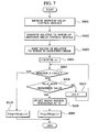
- FIG. 10 is a flowchart showing an operation of the multi-hop communication system.
- the radio station (either one of radio stations 21, 22, 31-33) transmits the usage inquiry for inquiring usage of the communication channel to the radio control station 1 without a relay by the other radio station, i.e., directly, when commencing communications via the radio control station 1.
- step S202 the radio control station 1 checks whether or not a vacant communication channel is available according to the usage inquiry transmitted in the step S201.
- the communication channel controller 15 that manages usage of the communication channel (s) handled by the radio control station 1 checks the usage of the communication channel and decides whether or not the vacant communication channel is available.
- step S208 the radio control station 1 determines that communication is not possible with the radio station, and then the radio control station 1 discontinues setting of the communication route to the radio station.
- step S203 the radio station measures a reception level of the pilot signal transmitted by the radio control station 1.
- step S204 whether or not the information signal is directly transmitted to the radio control station 1 is decided by the radio station based on the result of comparison of the reception level and the threshold being set.
- step S209 the radio station directly transmits the information signal to the radio control station 1 (i.e., single hop connection).
- step S205 the radio station transmits a relay control signal in order to request the other radio stations to relay the information signal.
- step S206 the radio station determines whether or not a relay of the information signal by the other radio station is possible based on the response relay control signal.
- step S207 the radio station transmits the information signal to the radio control station 1 through the other radio station (i.e., multi-hop connection).
- the radio control station 1 can assign a communication channel to be used in the radio station located on the determined communication route.
- FIG. 11 is a sequence chart showing a communication sequence between the radio stations 21, 31, 32 and the radio control station 1.
- step S301 the radio stations 21, 31, 32 ceceive the pilot signal from the radio control station 1 periodically.
- step S302 the radio station 32 transmits a usage inquiry for inquiring usage of the communication channel handled by the radio control station 1.
- step S303 the radio control station 1 checks whether or not a vacant communication channel is available based on the usage inquiry.
- the radio control station 1 transmits a usage notification that notifies usage of the communication channel to the radio station 32.
- step S304 whether or not the information signal is directly transmitted to the radio control station 1 is determined by the radio station 32 based on a reception level of the pilot signal received most recently.
- the radio station 32 may also determine the communication route when it receives the pilot signal every time. This alternative allows discovering an appropriate communication route more rapidly.
- step S305 the radio station 32 transmits a relay control signal for requesting a relay of the information signal to the radio stations 21 and 31.
- step S306 the radio stations 21 and 31 measure a reception level of the pilot signal transmitted by the radio control station 1 in response to the relay control signal transmitted by the radio station 32.
- step S307 the radio station 21 determines that the information signal to be transmitted by the radio station 32 can be relayed to the radio control station 1.
- step S308 the radio station 21 transmits a response relay control signal to the radio station 32 to notify that information signal to be transmitted by the radio station 32 can be relayed.
- step S309 the radio stations 21 and 32 determine the communication route for transmission/reception of the information signal based on the response relay control signal.
- the radio station 21 if the radio station 21 cannot directly transmit the information signal to the radio control station 1, the radio station 21 further transmits the response relay control signal, which the information of the radio station 21 is added, to the other radio station (e.g., the radio station 22).
- the radio station 22 determines whether or not the information signal to be transmitted by the radio station 32 can be directly relayed to the radio control station 1 is determined by the radio station 22. If the radio station 22 can relay the information signal to be transmitted by the radio station 32, the radio station 22 transmits a response relay control signal to notify the ability of the relay.
- the radio station 21 relays the response relay control signal transmitted by the radio station 22 to the radio station 32 so as to determine a communication route between the radio station 32 and the radio control station 1.
- the radio station may also add a value of a reception level of the pilot signal to the response relay control signal (or the relay control signal).
- the radio station relaying the information signal can be selected based on the reception level in addition to the SIR and the number of hops. This allows that the radio station can select only the radio station, of which reception level of the pilot signal is higher. It is therefore prevented that the radio station located in more distant position from the radio control station 1 is selected to set a communication route via other stations.
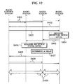
- FIG. 12 is a sequence chart showing a communication sequence between the radio stations 21, 31, 32 and the radio control station 1.
- the radio station determines that the information signal is directly relayed to the radio control station 1, the radio station transmits a communication route acquisition request to the radio control station 1.
- the radio control station 1 sets a communication route according to the communication route acquisition request, and transmits a communication route acquisition notification to each radio station.
- the radio control station 1 may transmits the communication route acquisition request and the radio station may transmit the communication route acquisition notification.
- step S401 the radio stations 21, 31, 32 ceceive the pilot signal from the radio control station 1 periodically.
- step S402 the radio station 32 transmits a usage inquiry for inquiring usage of the communication channel handled by the radio control station 1.
- step S403 the radio control station 1 checks whether or not a vacant communication channel is available based on the usage inquiry.
- the radio control station 1 transmits a usage notification that notifies usage of the communication channel to the radio station 32.
- step S404 whether or not the information signal is directly transmitted to the radio control station 1 is determined by the radio station 32 based on a reception level of the pilot signal received most recently.
- the radio station 32 may also determine the communication route when it receives the pilot signal every time. This alternative allows discovering an appropriate communication route more rapidly.
- step S405 the radio station 32 transmits a relay control signal for requesting a relay of the information signal by a multi-hop connection to the radio stations 21 and 31.
- step S406 the radio stations 21 and 31 measure a reception level of the pilot signal transmitted by the radio control station 1 in response to the relay control signal transmitted by the radio station 32.
- step S407 the radio station 21 determines that the information signal to be transmitted by the radio station 32 can be relayed to the radio control station 1.
- step S408 the radio station 21 transmits a communication route acquisition request for requesting acquisition of a communication route between the radio station 32 and the radio control station 1 to the radio control station 1.
- step S409 the radio control station 1 determines a communication route to the radio station 32 according to the communication route acquisition request transmitted by the radio station 21.
- the radio control station 1 then transmits a communication route acquisition notification for notifying information of the communication route (e.g., a station ID) to the radio stations 21 and 32.
- the both radio stations 21 and 31 can recognize the communication route between the radio station 32 and the radio control station 1 by the communication route acquisition notification.
- a communication route which has the smallest number of hops between the radio station and the radio control station 1 is selected.
- FIG. 13 is a diagram explaining an operation of the multi-hop communication system to select a communication route, which has the smallest number of hops.
- the radio station 31 commences communication with the radio control station 1 (i.e., the core network) is illustrated.
- the radio control station 1 i.e., the core network
- the numbers in the rectangle is correlated with a reception level of the pilot signal transmitted by the radio control station 1.
- the number means that the reception level is higher as the number decreases.
- "1" shown in the rectangle of the radio station 22 means the highest reception level in the radio stations 21, 22, 31-33.
- the radio station 31 Since the information signal cannot directly be transmitted between the radio station 31 and the radio control station 1, the radio station 31 transmits a relay control signal for requesting a relay of the information signal to the other radio stations.
- the radio stations 32 and 33 received the relay control signal transmitted by the radio station 31. It is further assumed that the information signal cannot directly be transmitted between the radio station 32, 33 and the radio control station 1.
- the radio stations 32 and 33 add the station ID, etc. (e.g. reception level of the pilot signal) to the relay control signal and transmits the relay control signal as a response relay control signal that the station ID, etc. is added.
- the station ID e.g. reception level of the pilot signal
- the radio station 32 receives the response relay control signal from the radio station 33.
- the radio station 33 receives the response relay control signal from the radio station 32.
- the response relay control signal transmitted by the radio station 33 is discarded in the radio station 32 based on the reception level.
- the radio station 32 discards the response relay control signal transmitted by the radio station 33.
- the response relay control signals transmitted by the radio station 32 and the radio station 33 are also discarded in the radio station 31.
- the response relay control signal is only relayed to the radio stations, which has a higher reception level. Therefore, the response relay control signal reaches the radio stations 21 and 22, which can directly relay the information signal to the radio control station 1.
- the radio stations 21 and 22 transmit a response relay control signal for notifying that a relay of the information signal is possible to the radio station 31.
- the following communication routes can be set (the number below means either radio station or radio control station).
- the radio station 31 selects the communication route (6) , which has the smallest number of hops (i.e., 3 hops).
- the radio control station 1 may notify the communication route acquisition notification of all the radio stations located on the communication route.
- the response relay control signal including the information of the radio station relayed the response relay control signal is also received by the radio control station 1.
- the radio control station 1 selects the communication route (6) as a communication route to the radio station 31 based on the response relay control signal received.
- the communication route is determined according to the relay control signal transmitted by the radio station commencing communication.
- the radio control station 1 has to transmit the relay control signal to the radio station.
- the radio control station 1 can transmit a communication route acquisition request for requesting acquisition of a communication route, and the radio station can discover a communication route between the destination radio station and the radio control station 1 according to the communication route acquisition request.
- the radio control station 1 determines the communication route discovered by the radio station as a communication route between the between the destination radio station and the radio control station 1.
- the radio control station 1 the radio stations (radio stations 21, 22, 31-33) and a multi-hop communication method, it is feasible that acquisition of an appropriate communication routes between the radio stations or between the radio station and the radio control station with small amount of control signals.
- the radio station since the radio station transmits the usage inquiry to check whether or not a vacant communication channel is available before it commences communication, transmission of the information signal while no vacant communication channel is available is prevented. Therefore, communication can be conducted more surely in the multi-hop communication system even large amount of traffic occurs in the multi-hop communication system.
- the radio station since the radio station, of which distance to the radio control station 1 is shorter, is selected based on a reception level of the pilot signal, the communication route between the radio station and the radio control station 1, which has the minimum number of hops, can be set.
Abstract

Description
- This application is based upon and claims the benefit of priority from the prior Japanese Patent Applications No. P2003-044945, filed on February 21, 2003; the entire contents of which are incorporated herein by reference.
- The present invention relates to a multi-hop communication system and a multi-hop communication method, which are configured by a radio control station and radio stations. The present invention also relates to a radio control station and a radio station used in the multi-hop communication system.
Specifically, the present invention relates to a cellular phone system, in which a radio base station acts as the radio control station, and a wireless LAN, in which an access point acts as the radio control station. - In an ad hoc network, communications between two stations, which cannot directly communicate with each other, are achieved using multiple stations. The multiple stations relay signals transmitted by the origin to the destination (which is called "multi-hop connection"). As for the ad hoc network, various kinds of commutation route discovery protocols have been proposed, i.e., DSR (Direct Source Routing) and AODV (Ad hoc On demand Distance Vector).
- In such ad hoc networks, a centralized control station like the base station in the cellular phone system does not exist. Therefore, normally the radio station itself discovers a communication route autonomously.
- In this regard, the multi-hop cellular, in which a communication route from the radio station to the base station is acquired by a multi-hop connection, has also been proposed. In the multi-hop cellar, since the radio station can access to a core network via the base station, communications with the destination becomes possible if a communication route up to the base station is acquired. Therefore, probability of connection with the distant destination is higher than the ad hoc network.
- However, in the multi-hop cellular, methods of communication between the radio stations and acquisition of a communication route between the radio station and the base station have still been considered. It is highly desirable that such processes are performed within a short period of time with a small amount of controlling signals.
- Further, communications cannot be performed between the radio stations if communication channels handled by the base station are fully occupied. In this case, since packets, which are not received by any radio station/base station, are transmitted, resources of the multi-hop cellular are wasted.
- Moreover, it is known that in a radio communication system, higher transmission power is required as transmission speed (bit rate) increases. Therefore, power consumption at the radio station/base station may become excessive if the bit rates for transmitting both control signal and information signal are increased simultaneously.
- The present invention has been made in view of the above perspectives, and thus has an object of providing a multi-hop communication system, a radio control station, a radio station and a multi-hop communication method, which enables acquisition of an appropriate communication routes between the radio stations or between the radio station and the radio control station with small amount of control signals.
- In order to achieve the above object, a multi-hop communication system according to the present invention, which is configured by a radio control station that is connected to a core network, and radio stations that relay an information signal transmitted by other radio stations, determines a communication route for a control signal and a communication route for an information signal by different independent processes. The control signal and the information signal are transmitted by the determined communication routes.
-
- FIG. 1A is a schematic diagram showing overall configuration of a multi-hop communication system according to a first embodiment;
- FIG. 1B is an area configuration of the multi-hop communication system according to the first embodiment;
- FIG. 2A is a block diagram of a radio control station according to the first embodiment;
- FIG. 2B is a block diagram of a radio station according to the first embodiment;
- FIG. 3 is a flowchart showing a multi-hop communication method according to the first embodiment;
- FIG. 4A is a block diagram of a radio control station according to a second embodiment;
- FIG. 4B is a block diagram of a radio station according to the second embodiment;
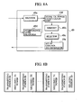
- FIG . 5A is a block diagram of a communication route selector located in the radio station according to the second embodiment;
- FIG. 5B is a diagram showing configuration of a relay control signal according to the second embodiment;
- FIG. 6 is a flowchart showing processes performed in the communication route selector according to the second embodiment;
- FIG. 7 is a flowchart showing processes performed in the communication route selector according to the second embodiment;
- FIG. 8A is block diagram of a communication route selector located in the radio station according to the second embodiment;
- FIG. 8B is a diagram showing configuration of the relay control signal according to the second embodiment;
- FIG. 9 is a flowchart showing processes performed in the communication route selector according to the second embodiment;
- FIG. 10 is a flowchart showing a multi-hop communication method according to the second embodiment;
- FIG. 11 is a sequence chart showing a communication sequence according to the multi-hop communication system in the second embodiment;
- FIG. 12 is a sequence chart showing a communication sequence according to the multi-hop communication system in a third embodiment; and
- FIG. 13 is a diagram explaining an operation of the multi-hop communication system to select a communication route, which has the smallest number of hops.
-
- A first embodiment of the present invention will now be described with reference to the drawings - FIG. 1A is a schematic diagram showing overall configuration of the multi-hop communication system.
- As shown in FIG. 1A, the multi-hop communication system is configured by a
radio control station 1 connected to a core network, e.g., a wideband wired network, andradio stations radio control station 1. Incidentally, area A means an area, in which theradio control station 1 can directly transmits/receives an information signal with theradio stations - As shown in FIG. 1B, a plurality of the area A is deployed. Further, an area B is located outside of each area A. Each area B has a shape of a ring and is overlapped with the other areas B.
- As shown in FIG. 1A, the
radio stations radio control station 1. On the other hand, the radio stations 31-33 are located outside of the area A. Therefore, the radio stations 31-33 cannot directly transmit the information signal to theradio control station 1. However, the radio stations 31-33 are located in the area B of theradio control station 1. The radio stations 31-33 can transmit/receive only the control signal, i.e., a pilot signal, to theradio control station 1. - In the multi-hop communication system in the embodiment, the control signal, i.e., a pilot signal, is transmitted with a lower bit rate in comparison with the information signal.
- FIG. 2A is a block diagram of the
radio control station 1, and FIG. 2B is a block diagram of theradio stations - As shown in FIG. 2A, the
radio control station 1 has aradio communication unit 11 which transmits/receives the information signal and the control signal using a radio communication scheme (e.g., CDMA) , a control signal TX/RX unit 12 which transmits/receives the control signal, acontrol signal processor 14 which generates/processes the control signal. - Further, the
radio control station 1 has acommunication channel controller 15 which transmits a "usage notification" indicating usage of communication channels managed by theradio control station 1 to theradio stations - Moreover, the
radio control station 1 also has acommunication route determiner 17 which determines a communication route for the information signal and the control signal, an information signal TX/RX unit 13 which transmits/receives the information signal, and aninformation signal processor 16 which generates/processes the information signal. - The
communication route determiner 17 determines a communication route for transmission/reception of the control signal by a different independent process from the process for determination of a communication route for transmission/reception of the information signal. - Specifically, the
communication route determiner 17 determines if theradio control station 1 can directly transmit/receive the information signal with the radio station based on a reception level of the control signal (e.g. , a pilot signal) received at the control signal TX/RX unit 12. - At this point in time, transmission/reception of the control signal is performed directly with the radio station as a different independent process using the control signal TX/
RX unit 12. The process has no relations to the processes for determination of a communication route for the information signal. It means that two different communication routes may be set between theradio control station 1 and the radio station. Such as a communication route for the control signal, of which bit rate is lower than the information signal, and a communication route for the information signal. - The control signal, of which bit rate is lower than the information signal, can cover a larger transmission area in comparison with the information signal. Therefore, the
radio control station 1 and the radio station (21, 22, 31-33) can transmit/receive the control signal even if theradio control station 1 and the radio station (21, 22, 31-33) is distant, as they cannot directly transmit/receive the information signal. - Further, the
communication route determiner 17 can estimate the distance between theradio control station 1 and the radio station according to the reception level of the control signal (e.g. , the pilot signal) transmitted by the radio station. Thecommunication route determiner 17 can also determine whether transmission/reception of the information signal directly performed with the radio station. - Incidentally, the control signal TX/
RXunit 12 can directly transmit/receive the information signal between theradio contrcl station 1 and the radio station. Further, the control signal TX/RX unit 12 can perform the multi-hop connection for transmission/reception of the information signal via a plurality of the radio stations. - Moreover, in this embodiment, although the
communication route determiner 17 is located in theradio control station 1, the present invention is not limited to such embodiment. The communication route determiner having above described function may be located in theradio station - As shown in FIG. 2B, the
radio stations radio communication unit 41 which transmits/receives the information signal and the control signal using a radio communication scheme (e.g., CDMA) , a control signal TX/RX unit 42 which transmits/receives the control signal, acontrol signal processor 44 which generates/processes the control signal. - Further, the
radio stations RX unit 43 which transmits/receives the information signal and aninformation signal processor 46 which generates/processes the information signal. - Incidentally, the
control signal processor 44 can transmit a usage inquiry for inquiring usage of the communication channel handled by theradio control station 1 through the control signal. Thecontrol signal processor 44 can also transmit/receive the information signal according to a usage notification that is a response to the usage inquiry. - Hereinafter, an operation of the multi-hop communication system according to the embodiment will be described. FIG. 3 is a flowchart showing an operation of the multi-hop communication system.
- As shown in FIG. 3, in step S101, the radio station (either one of
radio stations radio control station 1 without a relay by the other radio station, i.e., directly, when commencing communications via theradio control station 1. - In step S102, the
radio control station 1 checks whether or not a vacant communication channel is available according to the usage inquiry transmitted in the step S101. - Specifically, the
communication channel controller 15 that manages usage of the communication channel (s) handled by theradio control station 1 checks the usage of the communication channel and decides whether or not the vacant communication channel is available. - If the vacant channel is available ("Y" in the step S102) , in step S103, the
radio control station 1 discovers a communication route for transmission/reception of the information signal. - In step S104, the
radio control station 1 commences transmission/reception of the information signal, i.e., communications with the radio station using the communication route discovered in the step S103. - On the other hand, if no vacant channel is available ("N" in the step S102), in step S105, the
radio control station 1 determines that communication is not possible with the radio station and then discontinues setting of the communication route to the radio station. - According to the first embodiment heretofore described, the radio station (the
radio stations radio control station 1 before transmission/reception of the information signal. Further, the radio station determines setting of a communication route based on the availability of the vacant channel. - Therefore, performing the process of the communication channeL setting by the radio station with the
radio control station 1 can be reduced even if no vacant communication channel is available. - Specifically, since packets for communication route discovery is not transmitted when the communication channels are fully occupied, a waste of resources in the multi-hop communication system can be prevented.
- Hereinafter, a second embodiment of the present invention will be described. FIG. 4 is a schematic diagram showing overall configuration of the multi-hop communication system according to the embodiment. In the embodiment, whether or not communication is directly conducted between the radio station and the radio control station is determined based on a reception level of the control signal (e.g., a pilot signal).
- As shown in FIG. 4A, it is similar to the first embodiment, the
radio control station 1 has aradio communication unit 11 which transmits/receives the information signal and the control signal using a radio communication scheme (e. g. , CDMA) , a control signal TX/RXunit 12 which transmits/receives the control signal, acontrol signal processor 14 which generates/processes the control signal. - Further, the
radio control station 1 has acommunication channel controller 15 which transmits a "usage notification" indicating usage of communication channels managed by theradio control station 1 to theradio stations - Moreover, the
radio control station 1 also has acommunication route determiner 17 which determines a communication route for the information signal and the control signal, an information signal TX/RX unit 13 which transmits/receives the information signal, and aninformation signal processor 16 which generates/processes the information signal. - The
communication route determiner 17 determines a communication route for transmission/reception of the control signal by a different independent process from the process for determination of a communication route for transmission/reception of the information signal. - Specifically, the
communication route determiner 17 determines if theradio control station 1 can directly transmit/receive the information signal with the radio station based on a reception level of the control signal (e.g., a pilot signal) received at the control signal TX/RX unit 12. - At this point in time, transmission/reception of the control signal is performed directly with the radio station as a different independent process using the control signal TX/
RX unit 12. The process has no relations to the processes for determination of a communication route forthe information signal. It means that two different communication routes may be set between theradio control station 1 and the radio station. Such as a communication route for the control signal, of which bit rate is lower than the information signal, and a communication route for the information signal. - The control signal, of which bit rate is lower than the information signal, can cover a larger transmission area in comparison with the information signal. Therefore, the
radio control station 1 and the radio station (21, 22, 31-33) can transmit/receive the control signal even if theradio control station 1 and the radio station (21, 22, 31-33) is distant, as they cannot directly transmit/receive the information signal. - Further, the
communication route determiner 17 can estimate the distance between theradio control station 1 and the radio station according to the reception level of the control signal (e. g. , the pilot signal) transmittedby the radio station. Thecommunication route determiner 17 can also determine whether transmission/reception of the information signal directly performed with the radio station. - Incidentally, the control signal TX/
RX unit 12 can directly transmit/receive the information signal between theradio control station 1 and the radio station. Further, the control signal TX/RX unit 12 can perform the multi-hop connection for transmission/reception of the information signal via a plurality of the radio stations. - Moreover, in this embodiment, although the
communication route determiner 17 is located in theradio control station 1, the present invention is not limited to such embodiment. The communication route determiner having above described function may be located in theradio station - As shown in FIG. 4B, the
radio stations radio communication unit 41 which transmits/receives the information signal and the control signal using a radio communication scheme (e.g., CDMA) , a control signal TX/RX unit 42 which transmits/receives the control signal, acontrol signal processor 44 which generates/processes the control signal. - Further, the
radio stations RX unit 43 which transmits/receives the information signal and aninformation signal processor 46 which generates/processes the information signal. - Moreover, the
radio stations relay controller 45, a receptionsignal level measurer 47, adecision unit 48 and acommunication route selector 49. - The
relay controller 45 transmits a "relay control signal" for requesting a relay of the information signal to the other station and sets a communication route to the radio control station via the other station according to a "response relay control signal" that is a response to the relay control signal. Incidentally, in the embodiment, therelay controller 45 configures a first relay controller. - Further, the
relay controller 45 receives a relay control signal requesting a relay of the information signal from the other station. Therelay controller 45 then transmits a response relay control signal that is a response to the relay control signal and sets a communication route from the other radio station to theradio control station 1. Incidentally, in the embodiment, therelay controller 45 configures a second relay controller. - The reception
signal level measurer 47 measures a reception level of a pilot signal transmitted by theradio control station 1 and sends a result of the measurement to thedecision unit 48. - The
decision unit 48 decides whether or not communication is directly conducted with theradio control station 1 based on a reception level of the pilot signal received by the control signal TX/RX unit 42. - Specifically, the
decision unit 48 stores the threshold (s) for the reception level of the pilot signal. Then whether or not information signal is directly transmitted to theradio control station 1 is decided by thedecision unit 48 based on the result of comparison of the reception level and the threshold. - The
communication route selector 49 selects a radio station satisfying a prescribed condition regarding a communication state if a plurality of the other radio stations transmitted the response relay control signal. - The
communication route selector 49 can select a communication route according to the methods described below. - In this method, the
communication route selector 49 selects a communication route to theradio control station 1 based on an SIR (signal to interference ratio) and the number of hops. - As shown FIG. 5A, the
communication route selector 49 is configured by adecoder 49a for decoding a received control signal, aninterference level measurer 49d for measuring a level of interference imposed on the pilot signal, aselector 49c for selecting the other radio station which relays the information signal, amemory 49b for memorizing the number of hops, and a relaycontrol signal generator 49e for adding information of the radio station itself to the received relay control signal (or the response relay control signal) and generating a new response relay control signal. - Further, as shown in FIG. 5B, a station ID, source station ID, an interference level and the number of hops up to the
radio control station 1 are included in the response relay control signal. The radio station adds the station ID, the interference level and the number of hops to the response relay control signal received from the other radio station and then transmits the response relay control signal. - Each radio station received the relay control signal (or the response relay control signal) selects a radio station to be located on a next hop based on the SIR and the number of hops.
- In other words , each radio station selects a radio station, of which the number of hops to the
radio control station 1 is smallest based on the response relay control signal. Further, if two or more communication routes having the same number of hops are available, each radio station selects a ratio station, of which SIR is highest. - Specifically, as shown in FIG. 6, in step S501, the control signal TX/
RX unit 42 receives the relay control signals (or the response relay control signals) from the other radio station. - In step S502, the
communication route selector 49 initializes the counter i for counting the number of hops. - In step S503, the
communication route selector 49 selects the response relay control signal, of which number of hops (Nhop) is equal to "i", and generates a family "S" configured by the response relay control signal, of which number of hops (Nhop) is equal to "i". - In step S504, the
communication route selector 49 checks whether or not the family "S" is null. - If the family "S" is null ("Y" in the step S504) , in step S505, the
communication route selector 49 checks whether or not the value of the counter "i" is below the maximum number of hops determined in advance. - If the value of the counter "i" is not below the maximum number of hops ("N" in the step S505), in step S506, the
communication route selector 49 adds "1" to the counter "i" . Thecommunication route selector 49 again performs processes starting from the step S503 based on the new value of the counter "i". - On the other hand, if the family "S" is not null ("N" in the step S504), in step S507, the
communication route selector 49 computes a relative transmission power of the response relay control signal (the pilot signal) included in the family "S". - In step S508, the
communication route selector 49 selects a radio station, of which relative transmission power is smallest based on the relative transmission power. - In step S509, the
communication route selector 49 adds "1" to the counter "i" and then concludes the process. - Further, if the value of the counter "i" is equal to the maximum number of hops ("Y" in the step S505) , in step S506, the
communication route selector 49 reduces "1" from the counter "i" and then concludes the process. - According to the method described above, the radio station can select a radio station, of which number of hops up to the
radio control station 1 is smallest as well as the SIR is largest as a radio station to relay the information signal. The radio station then transmits the response relay control signal containing information of the radio station itself (i.e., the station ID, the interference level and the number of hops) to the selected radio station. - As a second method, the
communication route selector 49 can select a radio station, of which relative transmission power is smallest. The relative transmission power is computed base on an SIR of the response relay control signal (the pilot signal) and an interference level imposed to the response relay control signal. - In this method, the radio station computes a relative transmission power of each response relay control signal received from the other stations. The radio station then sorts the values of the relative transmission power in an ascending order.
- Further, the radio station checks whether or not the number of hops is below a prescribed value about the sorted response relay control signal. If the number of hops is below the prescribed value, the radio station selects the radio station that transmitted such response relay control signal as a radio station to relay the information signal.
- Incidentally, the relative transmission power is computed based on the difference between the SIR of the response relay control signals and the interference level imposed to the response relay control signal.
- As shown in FIG. 7, in step S601, the control signal TX/
RX unit 42 receives the response relay control signals (or the relay control signals) from the other radio station. - In step S602, the
communication route selector 49 computes the relative transmission power of all the response relay control signals. - In step S603, the
communication route selector 49 sorts the values of the relative transmission power in an ascending order. - In step S604, the
communication route selector 49 initializes the counter i for counting the position in the sorted values of the relative transmission power. - In step S605, the
communication route selector 49 checks whether or not value positioned at "S" is null. - If value positioned at "S" is not null ("N" in the step S605), in step S606, the
communication route selector 49 checks that the number of hops (Nhop) up to theradio control station 1 is equal to or less than the prescribed value. - If the number of hops is larger than the prescribed value ("N" in the step S606) , in step S607, the
communication route selector 49 adds "1" to the counter i and again performs processes starting from the step S605 based on the value of the response relay control signal positioned at a new position "S". - Further, if value is not located at the position "S" ("N" in the step S605) , in step S610, the
communication route selector 49 reduces "1" for the number of hops (Nhop) and then concludes the process. - If the number of hops is equal to or smaller than the prescribed value ("Y" in the step S606), in step S608, the
communication route selector 49 selects the radio station that transmits the response relay control signal positioned at "S". - In step S609, the
communication route selector 49 adds "1" for the number of hops (Nhop) and then concludes the process. - According to the method described above, the radio station can select a next hop radio station, of which the number of hops up to the
radio control station 1 is equal to or below the prescribed value, and of which relative transmission power is smallest, as a radio station to relay the information signal. - Incidentally, large transmission power is normally required for transmission of the information signal, which is transmitted with a high bit rate. In view of this, the radio station (decision unit 48) may change threshold value for the reception level according to a transmission speed of the information signal.
- Specifically, the radio station (decision unit 48) changes the threshold value for the reception level of the response relay control signal according to the bit rate (transmission speed) used in the information signal TX/
RX unit 43. For example, the radio station (decision unit 48) increases the threshold value if the bit rate used in the information signal TX/RX unit 43 increases. - As a third method, the
communication route selector 49 can select a communication route so as to minimize the total transmission power of the radio stations relaying the information signal. - In this method, as shown in FIG. 8A, the
communication route selector 49 is configured by adecoder 49a, amemory 49b, aselector 49c, aninterference level measurer 49d, a relaycontrol signal generator 49e and a total transmissionpower computation unit 49f. - Further, as shown in FIG. 8B, in a response relay control signal, a transmitting station ID indicating a radio station that transmits a relay control signal, or a relay station ID indicating a radio station that relays the relay control signal (or the response relay control signal) , and required transmission power are included.
- The radio station to relay the relay control signal (or the response relay control signal) adds the identifier of the radio station itself and value of the required transmission power. Therefore, such information for all the radio stations located on the communication route can be gathered.
- Specifically, as shown in FIG. 9, in step S701, the control signal TX/
RX unit 42 receives the relay control signals (or the response relay control signals) from the other radio station. - In step S702, the
communication route selector 49 measures an SIR of the response relay control signal and retrieves the value o the required transmission power included in the response relay control signal. - In step S703, the
communication route selector 49 computes the required transmission power at the radio station based on the measured SIR in the step S702, the desired SIR and predetermined value of the transmission power at the radio station that transmitted the relay control signals (or the response relay control signals). - Further, the
communication route selector 49 computes the total sum of the values of the required transmission power included in the response relay control signal. - In step S704, the
communication route selector 49 compares the total sum of the required transmission power computed in the step S703 and the total sum of the required transmission power, which has already been memorized in thememory 49b. - If the value of computed total sum is smaller than the memorized total sum ("Y" in the step S704), in step S705, the
communication route selector 49 replaces the memorized total sum by the computed total sum so as to update the information in the in thememory 49b. - In step S706, the
communication route selector 49 checks whether or not the other response relay control signal has been received at the control signal TX/RX unit 42. - If the other response relay control signal has been received ("Y" in the step S706) , the
communication route selector 49 again performs the processes of the steps S701 through S705 for the other response relay control signal. - On the other hand, if no response relay control signal has been received ("N" in the step S706), in step S707, the
communication route selector 49 starts a timer. - In step S708, the
communication route selector 49 checks elapsed time. - If a prescribed time elapsed ("Y" in the step S708), in step S709, the
communication route selector 49 selects a radio station of a next hop, which relays the information signal, according to the information included in the response relay control signal. Further, thecommunication route selector 49 adds the identifier of the radio station itself and the value of the computed transmission power to the response relay control signal. - In step S710, the
communication route selector 49 transmits the response relay control signal, which the identifier and the value have been added, to the other radio stations of the next hop. - Hereinafter, an operation of the multi-hop communication system according to the embodiment will be described. FIG. 10 is a flowchart showing an operation of the multi-hop communication system.
- As shown in FIG. 10, in step S201, the radio station (either one of
radio stations radio control station 1 without a relay by the other radio station, i.e., directly, when commencing communications via theradio control station 1. - In step S202, the
radio control station 1 checks whether or not a vacant communication channel is available according to the usage inquiry transmitted in the step S201. - Specifically, the
communication channel controller 15 that manages usage of the communication channel (s) handled by theradio control station 1 checks the usage of the communication channel and decides whether or not the vacant communication channel is available. - If no vacant channel is available ("N" in the step S202), in step S208, the
radio control station 1 determines that communication is not possible with the radio station, and then theradio control station 1 discontinues setting of the communication route to the radio station. - On the other hand, if the vacant channel is available ("Y" in the step s202) , in step S203, the radio station measures a reception level of the pilot signal transmitted by the
radio control station 1. - In step S204, whether or not the information signal is directly transmitted to the
radio control station 1 is decided by the radio station based on the result of comparison of the reception level and the threshold being set. - If the reception level exceeds the threshold ("Y" in the step S204) , in step S209, the radio station directly transmits the information signal to the radio control station 1 (i.e., single hop connection).
- On the other hand, if the reception level does not exceed the threshold ("N" in the step S204), in step S205, the radio station transmits a relay control signal in order to request the other radio stations to relay the information signal.
- In step S206, the radio station determines whether or not a relay of the information signal by the other radio station is possible based on the response relay control signal.
- If the relay of the information signal by the other radio station is possible ("Y" in the step S206) , in step S207, the radio station transmits the information signal to the
radio control station 1 through the other radio station (i.e., multi-hop connection). - Incidentally, the
radio control station 1 can assign a communication channel to be used in the radio station located on the determined communication route. - Hereinafter, the multi-hop communication method shown in FIG. 10 will be further described. FIG. 11 is a sequence chart showing a communication sequence between the
radio stations radio control station 1. - As shown in FIG. 11, in step S301, the
radio stations radio control station 1 periodically. - In step S302 , the
radio station 32 transmits a usage inquiry for inquiring usage of the communication channel handled by theradio control station 1. - In step S303, the
radio control station 1 checks whether or not a vacant communication channel is available based on the usage inquiry. Theradio control station 1 transmits a usage notification that notifies usage of the communication channel to theradio station 32. - In step S304, whether or not the information signal is directly transmitted to the
radio control station 1 is determined by theradio station 32 based on a reception level of the pilot signal received most recently. - Incidentally, in this communication sequence, although the
radio station 32 determines the communication route when commencing communication, theradio station 32 may also determine the communication route when it receives the pilot signal every time. This alternative allows discovering an appropriate communication route more rapidly. - In step S305, the
radio station 32 transmits a relay control signal for requesting a relay of the information signal to theradio stations - In step S306, the
radio stations radio control station 1 in response to the relay control signal transmitted by theradio station 32. - In step S307, the
radio station 21 determines that the information signal to be transmitted by theradio station 32 can be relayed to theradio control station 1. - In step S308, the
radio station 21 transmits a response relay control signal to theradio station 32 to notify that information signal to be transmitted by theradio station 32 can be relayed. - In step S309, the
radio stations - Incidentally, if the
radio station 21 cannot directly transmit the information signal to theradio control station 1, theradio station 21 further transmits the response relay control signal, which the information of theradio station 21 is added, to the other radio station (e.g., the radio station 22). - Then, whether or not the information signal to be transmitted by the
radio station 32 can be directly relayed to theradio control station 1 is determined by theradio station 22. If theradio station 22 can relay the information signal to be transmitted by theradio station 32, theradio station 22 transmits a response relay control signal to notify the ability of the relay. - Further, the
radio station 21 relays the response relay control signal transmitted by theradio station 22 to theradio station 32 so as to determine a communication route between theradio station 32 and theradio control station 1. - Moreover, the radio station may also add a value of a reception level of the pilot signal to the response relay control signal (or the relay control signal).
- According to this arrangement, the radio station relaying the information signal can be selected based on the reception level in addition to the SIR and the number of hops. This allows that the radio station can select only the radio station, of which reception level of the pilot signal is higher. It is therefore prevented that the radio station located in more distant position from the
radio control station 1 is selected to set a communication route via other stations. - Hereinafter, a third embodiment of the present invention will be described. FIG. 12,is a sequence chart showing a communication sequence between the
radio stations radio control station 1. - In the embodiment, if the radio station determines that the information signal is directly relayed to the
radio control station 1, the radio station transmits a communication route acquisition request to theradio control station 1. - Further, the
radio control station 1 sets a communication route according to the communication route acquisition request, and transmits a communication route acquisition notification to each radio station. Incidentally, theradio control station 1 may transmits the communication route acquisition request and the radio station may transmit the communication route acquisition notification. - As shown in FIG. 12, in step S401, the
radio stations radio control station 1 periodically. - In step S402, the
radio station 32 transmits a usage inquiry for inquiring usage of the communication channel handled by theradio control station 1. - In step S403, the
radio control station 1 checks whether or not a vacant communication channel is available based on the usage inquiry. Theradio control station 1 transmits a usage notification that notifies usage of the communication channel to theradio station 32. - In step S404, whether or not the information signal is directly transmitted to the
radio control station 1 is determined by theradio station 32 based on a reception level of the pilot signal received most recently. - Incidentally, in this communication sequence, although the
radio station 32 determines the communication route when commencingcommunication, theradio station 32 may also determine the communication route when it receives the pilot signal every time. This alternative allows discovering an appropriate communication route more rapidly. - In step S405, the
radio station 32 transmits a relay control signal for requesting a relay of the information signal by a multi-hop connection to theradio stations - In step S406, the
radio stations radio control station 1 in response to the relay control signal transmitted by theradio station 32. - In step S407, the
radio station 21 determines that the information signal to be transmitted by theradio station 32 can be relayed to theradio control station 1. - In step S408, the
radio station 21 transmits a communication route acquisition request for requesting acquisition of a communication route between theradio station 32 and theradio control station 1 to theradio control station 1. - In step S409, the
radio control station 1 determines a communication route to theradio station 32 according to the communication route acquisition request transmitted by theradio station 21. Theradio control station 1 then transmits a communication route acquisition notification for notifying information of the communication route (e.g., a station ID) to theradio stations - The both
radio stations radio station 32 and theradio control station 1 by the communication route acquisition notification. - Further, in the multi-hop communication method according to the embodiment, if a plurality of the communication routes is available, a communication route, which has the smallest number of hops between the radio station and the
radio control station 1 is selected. - FIG. 13 is a diagram explaining an operation of the multi-hop communication system to select a communication route, which has the smallest number of hops.
- In FIG. 13, the case where the
radio station 31 commences communication with the radio control station 1 (i.e., the core network) is illustrated. - Further, the numbers in the rectangle is correlated with a reception level of the pilot signal transmitted by the
radio control station 1. The number means that the reception level is higher as the number decreases. For example, "1" shown in the rectangle of theradio station 22 means the highest reception level in theradio stations - Since the information signal cannot directly be transmitted between the
radio station 31 and theradio control station 1, theradio station 31 transmits a relay control signal for requesting a relay of the information signal to the other radio stations. - Here, it is assumed that the
radio stations radio station 31. It is further assumed that the information signal cannot directly be transmitted between theradio station radio control station 1. - The
radio stations - In this case, the
radio station 32 receives the response relay control signal from theradio station 33. Similarly, theradio station 33 receives the response relay control signal from theradio station 32. Here, since the reception level of the pilot signal is added to the response relay control signal, the response relay control signal transmitted by theradio station 33 is discarded in theradio station 32 based on the reception level. - In other words, since the number correlated to the reception level is "4" in the
radio station 33, and it is "5" in theradio station 32, theradio station 32 discards the response relay control signal transmitted by theradio station 33. - Similarly, the response relay control signals transmitted by the
radio station 32 and theradio station 33 are also discarded in theradio station 31. - As heretofore described, the response relay control signal is only relayed to the radio stations, which has a higher reception level. Therefore, the response relay control signal reaches the
radio stations radio control station 1. - The
radio stations radio station 31. - Under the configuration shown in FIG. 13, the following communication routes can be set (the number below means either radio station or radio control station).
- (1) 31-33-34-22-1
- (2) 31-33-34-21-1
- (3) 31-32-33-34-22-1
- (4) 31-32-34-22-1
- (5) 31-32-34-21-1
- (6) 31-32-21-1
-
- The
radio station 31 selects the communication route (6) , which has the smallest number of hops (i.e., 3 hops). - In FIG. 13, four communication routes ((3)-(6)) exist between the
radio station 32 and theradio control station 1. Theradio station 32 notifies only the communication route (6) , which has the smallest number of hops, to theradio station 31. - Accordingly, only three communication routes (i.e., (1), (2) and (6)) are notified to the
radio station 31. This alleviates a load of selection of the communication route in theradio station 31. - Further, as shown in FIG. 12, the
radio control station 1 may notify the communication route acquisition notification of all the radio stations located on the communication route. In this method, the response relay control signal including the information of the radio station relayed the response relay control signal is also received by theradio control station 1. - The
radio control station 1 selects the communication route (6) as a communication route to theradio station 31 based on the response relay control signal received. - In the embodiment heretofore described, the communication route is determined according to the relay control signal transmitted by the radio station commencing communication. However, in the certain situation, e.g., an incoming call to a cellular phone (or mobile terminal) and delivery of e-mail to a cellular phone, the
radio control station 1 has to transmit the relay control signal to the radio station. - In this case, the
radio control station 1 can transmit a communication route acquisition request for requesting acquisition of a communication route, and the radio station can discover a communication route between the destination radio station and theradio control station 1 according to the communication route acquisition request. - Further, the
radio control station 1 determines the communication route discovered by the radio station as a communication route between the between the destination radio station and theradio control station 1. - As heretofore described, according to the multi-hop communication system, the
radio control station 1, the radio stations (radio stations - Further, according to the embodiments described above, since the radio station transmits the usage inquiry to check whether or not a vacant communication channel is available before it commences communication, transmission of the information signal while no vacant communication channel is available is prevented. Therefore, communication can be conducted more surely in the multi-hop communication system even large amount of traffic occurs in the multi-hop communication system.
- Moreover, according to the embodiments described above, since the radio station, of which distance to the
radio control station 1 is shorter, is selected based on a reception level of the pilot signal, the communication route between the radio station and theradio control station 1, which has the minimum number of hops, can be set. - The invention has been described in detail by referring to the embodiments. It is obvious to those skilled in the art that the invention is not restricted to the embodiments described above. The invention may be carried out as a corrected or modified embodiment not departing from the gist and scope specified by the scope of the claims of a patent. Therefore, the description of this specification aims at the representation of examples but does not have any limitation on the present invention.
Claims (19)
- A multi-hop communication system configured by a radio control station connected to a core network and radio stations that relay a signal transmitted from other radio station, wherein, the radio control station comprises:a control signal transmission/reception unit configured to transmit/receive a control signal for conducting communication with the radio station;an information signal transmission/reception unit configured to transmit/receive an information signal; anda communication route determiner configured to determine a communication route for the control signal and a communication route for the information signal by different independent processes, and the radio station comprises:a control signal transmission/reception unit configured to transmit/receive the control signal; andan information signal transmission/reception unit configured to transmit/receive the information signal.
- A multi-hop communication system configured by a radio control station connected to a core network and radio stations that relay a signal transmitted from other radio station , wherein, the radio control station comprises:a control signal transmission/reception unit configured to transmit/receive a control signal for conducting communication with the radio station;an information signal transmission/reception unit configured to transmit/receive an information signal; anda communication route determiner configured to determine a communication route for the control signal by a different independent process from determination of a communication route for the information signal, and the radio station comprising:a control signal transmission/reception unit configured to transmit/receive the control signal; andan information signal transmission/reception unit configured to transmit/receive the information signal.
- A radio control station connected to a core network and controls communication by a radio station that relays a signals transmitted by other radio station, comprises:a control signal transmission/reception unit configured to transmit/receive a control signal for conducting communication with the radio station;an information signal transmission/reception unit configured to transmit/receive an information signal; anda communication route determiner configured to determine a communication route for the control signal.
- A radio control station according to claim 3, the communication route determiner determines a communication route for the information signal by a different independent process from the determination of the communication route for the control signal.
- A radio control station according to claim 3, the communication route determiner transmits a communication route acquisition request to the radio station for acquisition of a communication route, and the communication route determiner determines a communication route based on a response to the communi cation route acquisition request transmitted by the radio station.
- A radio control station according to claim 3, further comprising a communication channel controller configured to transmit a usage notification that indicates usage of a communication channel handled by the radio control station.
- A radio control station according to claim 3, the communication route determiner determines a communication route to the radio station and transmits a communication route determination notification that notifies the communication route to a radio station located on the communication route.
- A radio control station according to claim 7, the communication route determiner assigns a communication channel to be used in the radio station located on the determined communication route.
- A radio station conducting communication via a radio control station connected to a core network, comprising:a control signal transmission/reception unit configured to transmit/receive the control signal;an information signal transmission/reception unit configured to transmit/receive the information signal; anda communication route determiner configured to determine a communication route for the control signal and a communication route for the information signal by different independent processes.
- A radio station according to claim 9, the communication route determiner transmits a usage inquiry to the radio station for inquiring usage of a communication channel handled by the radio control station and transmits/receives the information signal according to a usage notification that is a response to the usage inquiry.
- A radio station according to claim 9, further comprising a decision unit configured to decide whether or not communication is directly conducted with the radio control station based on a reception level of the control signal received by the control signal transmission/reception unit.
- A radio station according to claim 11, the decision unit changes a threshold for the reception level according to a transmission speed of the information signal and to decide whether or not communication is directly conducted with the radio control station based on a result of comparison of the reception level and the threshold.
- A radio station according to claim 9, further comprising a first relay controller configured to transmit a relay control signal to other station for requesting a relay of the information signal and to set a communication route to the radio control station via the other station according to a response relay control signal that is a response to the relay control signal.
- A radio station according to claim 13, further comprising a communication route selector configured to select a radio station satisfying a prescribed condition regarding a communication state if a plurality of the other radio station transmitted the response relay control signal.
- A radio station according to claim 9, further comprising a second relay controller configured to receive a relay control signal requesting a relay of the information signal from other station, to transmit a response relay control signal that is a response to the relay control signal and to set a communication route from the other radio station to the radio control station.
- A radio station according to claim 15, the second relay controller transmits the response relay control signal notifying ability of the relay of the information signal based on a reception level of the received response relay control signal.
- A radio station according to claim 14, wherein an information indicating a number of hops from the other radio station to the radio control station is included in the response relay control signal, and the communication route selector selects a radio station based the number of hops included in the response relay control signal.
- A radio station according to claim 14, wherein an information indicating an interference level is included in the response relay control signal, and the communication route selector selects a radio station based the interference level included in the response relay control signal.
- A multi-hop communication method used in a system configured by a radio control station connected to a core network and radio stations that relay a signal transmitted from other radio station, comprising:a usage inquiry step that the radio station transmits a usage inquiry for inquiring usage of a communication channel handled by the radio control station using a control signal for conducting communication with the radio control station;a communication route determination step that the radio control station determines a communication route for the control signal and a communication route for the information signal by different independent processes;a usage notification step that the radio control station transmits a usage notification indicating usage of the communication channel handled by the radio control station; andan information signal transmission step that the radio station and the radio control station transmit/receive the information signal using the communication route according to the usage notification.
Applications Claiming Priority (2)
| Application Number | Priority Date | Filing Date | Title |
|---|---|---|---|
| JP2003044945A JP4027818B2 (en) | 2003-02-21 | 2003-02-21 | Multihop communication system, radio control station, radio station, and multihop communication method |
| JP2003044945 | 2003-02-21 |
Publications (3)
| Publication Number | Publication Date |
|---|---|
| EP1450522A2 true EP1450522A2 (en) | 2004-08-25 |
| EP1450522A3 EP1450522A3 (en) | 2008-04-09 |
| EP1450522B1 EP1450522B1 (en) | 2012-01-25 |
Family
ID=32733003
Family Applications (1)
| Application Number | Title | Priority Date | Filing Date |
|---|---|---|---|
| EP20040003847 Expired - Fee Related EP1450522B1 (en) | 2003-02-21 | 2004-02-20 | Multi-hop communication system, radio station and multi-hop communication method |
Country Status (6)
| Country | Link |
|---|---|
| US (1) | US7619998B2 (en) |
| EP (1) | EP1450522B1 (en) |
| JP (1) | JP4027818B2 (en) |
| CN (1) | CN1305234C (en) |
| AU (1) | AU2004200692B2 (en) |
| CA (1) | CA2458192C (en) |
Cited By (1)
| Publication number | Priority date | Publication date | Assignee | Title |
|---|---|---|---|---|
| EP2293625A1 (en) * | 2009-09-03 | 2011-03-09 | Fujitsu Limited | Wireless device, wireless communication system, and wireless communication method |
Families Citing this family (39)
| Publication number | Priority date | Publication date | Assignee | Title |
|---|---|---|---|---|
| CN100461651C (en) * | 2003-01-31 | 2009-02-11 | 富士通株式会社 | Mobile radio terminal device |
| JP4539231B2 (en) * | 2004-08-24 | 2010-09-08 | Kddi株式会社 | Communication method and base station using automatic retransmission control in multi-hop communication |
| JP4896038B2 (en) * | 2004-12-21 | 2012-03-14 | パナソニック株式会社 | Communication method, mobile communication node and access router in network system |
| KR100899751B1 (en) | 2005-03-09 | 2009-05-27 | 삼성전자주식회사 | System and method for relaying signal in a communication system |
| JP4591958B2 (en) * | 2005-04-28 | 2010-12-01 | Kddi株式会社 | Wireless data communication handover method |
| CN100444679C (en) * | 2005-06-28 | 2008-12-17 | 中国人民解放军信息工程大学 | Channel distributing method in mixed network |
| CN1964225B (en) * | 2005-11-11 | 2013-03-13 | 上海贝尔阿尔卡特股份有限公司 | A method to control wireless access, relay station and base station |
| JP4818788B2 (en) * | 2006-04-17 | 2011-11-16 | 日本無線株式会社 | Wireless device |
| KR101330633B1 (en) * | 2006-06-08 | 2013-11-18 | 삼성전자주식회사 | Method and apparatus for wireless communication |
| KR101277954B1 (en) * | 2006-06-20 | 2013-06-27 | 삼성전자주식회사 | Method and system for relaying signal in a mobile communication system |
| JP4952138B2 (en) * | 2006-08-17 | 2012-06-13 | 富士通株式会社 | Relay station, radio base station, and communication method |
| JP4952135B2 (en) * | 2006-08-17 | 2012-06-13 | 富士通株式会社 | Wireless terminal, relay station, wireless base station, and communication method |
| JP5034369B2 (en) * | 2006-08-18 | 2012-09-26 | 富士通株式会社 | Wireless communication control method |
| US7826366B2 (en) | 2006-11-07 | 2010-11-02 | Microsoft Corporation | Joint channel assignment and routing in wireless networks |
| JP4983208B2 (en) * | 2006-11-07 | 2012-07-25 | 富士通株式会社 | Relay station, wireless communication method |
| US7680089B2 (en) * | 2006-11-16 | 2010-03-16 | Microsoft Corporation | Dynamic channel assignment and connectivity maintenance in wireless networks |
| KR100925269B1 (en) * | 2006-12-07 | 2009-11-05 | 한국전자통신연구원 | Method of optimal data transmission for improving data transmission rate in multi-hop wireless network |
| JP4866746B2 (en) * | 2007-01-19 | 2012-02-01 | 公益財団法人鉄道総合技術研究所 | Worker location warning system |
| WO2008097030A1 (en) * | 2007-02-07 | 2008-08-14 | Lg Electronics Inc. | Optimized random access channel (rach) access |
| KR100949986B1 (en) * | 2007-02-26 | 2010-03-30 | 삼성전자주식회사 | Apparatus and method for transmiting and receiving control information in multi-hop relay broadband wireless communication system |
| JP5038924B2 (en) * | 2008-01-25 | 2012-10-03 | 株式会社エヌ・ティ・ティ・ドコモ | Relay transmission system, base station, relay station and method |
| KR101459147B1 (en) * | 2008-02-04 | 2014-11-10 | 엘지전자 주식회사 | Method of transmitting transmit power control command in wireless communication system |
| KR101517241B1 (en) * | 2008-12-24 | 2015-05-06 | 연세대학교 산학협력단 | Method of selecting relay station |
| TWI466510B (en) * | 2009-02-12 | 2014-12-21 | Realtek Semiconductor Corp | Processing apparatus and transmission method thereof |
| EP2421307A4 (en) | 2009-04-17 | 2014-11-12 | Alcatel Lucent | Method, apparatus and device for selecting relay user and allocating downlink resource |
| JP5082148B2 (en) * | 2010-03-11 | 2012-11-28 | Necアクセステクニカ株式会社 | Wireless transmission / reception system, wireless transmission / reception method, and control program for wireless transmission / reception system |
| US20130083687A1 (en) * | 2010-07-02 | 2013-04-04 | Panasonic Corporation | Communication device |
| JP5609385B2 (en) * | 2010-07-29 | 2014-10-22 | 富士通株式会社 | Wireless communication system, wireless communication method, and relay station used in wireless communication system |
| GB2498765A (en) * | 2012-01-27 | 2013-07-31 | Renesas Mobile Corp | Discovery signalling in a device-to-device communication system |
| US9814052B2 (en) * | 2013-02-14 | 2017-11-07 | Mitsubishi Electric Corporation | Data distribution system, distribution device, terminal device, and data distribution method providing enhanced communication efficiency |
| CN103581968B (en) * | 2013-11-14 | 2017-03-22 | 苏州大学 | Excitation method and system for cooperation of data forwarding of self-government nodes of Ad hoc network |
| US8743758B1 (en) | 2013-11-27 | 2014-06-03 | M87, Inc. | Concurrent uses of non-cellular interfaces for participating in hybrid cellular and non-cellular networks |
| EP3852333A1 (en) | 2013-12-13 | 2021-07-21 | M87, Inc. | Methods and systems for secure connections for joining hybrid cellular and non-cellular networks |
| US10015720B2 (en) | 2014-03-14 | 2018-07-03 | GoTenna, Inc. | System and method for digital communication between computing devices |
| JP6211998B2 (en) * | 2014-06-19 | 2017-10-11 | Necプラットフォームズ株式会社 | Relay device, relay method, and computer program |
| US10243832B2 (en) | 2014-12-23 | 2019-03-26 | Industrial Technology Research Institute | Routing message delivery method applicable to network node and network node using the same and communication network using the same |
| CN108076115A (en) * | 2016-11-16 | 2018-05-25 | 法乐第(北京)网络科技有限公司 | Share method, apparatus, system and the electronic equipment of vehicle-mounted router |
| JP7152636B2 (en) * | 2017-12-26 | 2022-10-13 | 国立大学法人京都大学 | Communication device and communication method |
| JP7069099B2 (en) * | 2019-11-13 | 2022-05-17 | Hapsモバイル株式会社 | Systems, controls, programs, and control methods |
Citations (1)
| Publication number | Priority date | Publication date | Assignee | Title |
|---|---|---|---|---|
| US20010036810A1 (en) | 2000-03-09 | 2001-11-01 | Larsen James David | Routing in a multi-station network |
Family Cites Families (34)
| Publication number | Priority date | Publication date | Assignee | Title |
|---|---|---|---|---|
| CA2048306A1 (en) | 1990-10-02 | 1992-04-03 | Steven P. Miller | Distributed configuration profile for computing system |
| US5504746A (en) * | 1991-10-01 | 1996-04-02 | Norand Corporation | Radio frequency local area network |
| MY123040A (en) * | 1994-12-19 | 2006-05-31 | Salbu Res And Dev Proprietary Ltd | Multi-hop packet radio networks |
| JP3242283B2 (en) | 1995-04-26 | 2001-12-25 | 株式会社日立製作所 | Wireless communication system and mobile wireless terminal device |
| US6141319A (en) * | 1996-04-10 | 2000-10-31 | Nec Usa, Inc. | Link based alternative routing scheme for network restoration under failure |
| US5964841A (en) * | 1997-03-03 | 1999-10-12 | Cisco Technology, Inc. | Technique for handling forwarding transients with link state routing protocol |
| JPH10313477A (en) * | 1997-05-14 | 1998-11-24 | Oki Electric Ind Co Ltd | Channel selection method in simplified base station for radio terminal |
| US6751196B1 (en) * | 1997-08-27 | 2004-06-15 | Philips Electronics North America Corp. | Apparatus and method for peer-to-peer link monitoring of a wireless network with centralized control |
| US6377809B1 (en) * | 1997-09-16 | 2002-04-23 | Qualcomm Incorporated | Channel structure for communication systems |
| SE521227C2 (en) * | 1999-02-22 | 2003-10-14 | Ericsson Telefon Ab L M | Mobile radio system and a method for channel allocation in a mobile radio system |
| EP1043016B1 (en) * | 1999-03-30 | 2014-08-20 | Sodic Sa | A plant extract based on glycerides,phospholipids and phytosphingolipids, a method for the preparation of this extract and a cosmetic composition containing the same |
| US6801775B1 (en) * | 1999-06-23 | 2004-10-05 | At&T Wireless Services, Inc. | Establishing a communication channel in a wireless network |
| US6574266B1 (en) * | 1999-06-25 | 2003-06-03 | Telefonaktiebolaget Lm Ericsson (Publ) | Base-station-assisted terminal-to-terminal connection setup |
| AU7549500A (en) * | 1999-09-30 | 2001-04-30 | Telefonaktiebolaget Lm Ericsson (Publ) | Transmit power control |
| US6836463B2 (en) * | 1999-10-15 | 2004-12-28 | Nokia Corporation | System for communicating labeled routing trees to establish preferred paths and source routes with local identifiers in wireless computer networks |
| DE10001098A1 (en) * | 2000-01-13 | 2001-07-19 | Definiens Ag | Process for the decentralized transmission and distribution of user data between participants in a telecommunications network |
| US6996069B2 (en) * | 2000-02-22 | 2006-02-07 | Qualcomm, Incorporated | Method and apparatus for controlling transmit power of multiple channels in a CDMA communication system |
| JP3451233B2 (en) | 2000-02-24 | 2003-09-29 | 日本電信電話株式会社 | Multi-hop wireless networks and radio stations |
| AU2001239929A1 (en) | 2000-02-28 | 2001-09-12 | Innuity, Inc. | System and method for generating internet services |
| FI114369B (en) * | 2000-03-31 | 2004-09-30 | Keijo Laehetkangas | telecommunications networks |
| JP2002026923A (en) | 2000-07-06 | 2002-01-25 | Nippon Hoso Kyokai <Nhk> | Self-proliferating wireless distribution network |
| US6704301B2 (en) * | 2000-12-29 | 2004-03-09 | Tropos Networks, Inc. | Method and apparatus to provide a routing protocol for wireless devices |
| US6965575B2 (en) * | 2000-12-29 | 2005-11-15 | Tropos Networks | Selection of routing paths based upon path quality of a wireless mesh network |
| US20030016650A1 (en) * | 2001-07-17 | 2003-01-23 | Felix Missel | Method used to create multihop RF network based on a low performance 8 bit microcontroller |
| US7046966B2 (en) * | 2001-08-24 | 2006-05-16 | Kyocera Wireless Corp. | Method and apparatus for assigning data rate in a multichannel communication system |
| US20030058826A1 (en) * | 2001-09-24 | 2003-03-27 | Shearer Daniel D. M. | Multihop, multi-channel, wireless communication network with scheduled time slots |
| DE60222282T2 (en) * | 2001-09-27 | 2008-06-12 | Telefonaktiebolaget Lm Ericsson (Publ) | MULTIPLE ROUTING PROCESS FOR DISTRIBUTED WI-FI NETWORKS |
| WO2003032527A1 (en) * | 2001-10-04 | 2003-04-17 | Ntt Docomo, Inc. | Radio control apparatus, base station, mobile communication method, mobile communication program, recording medium containing the same, and mobile communication system |
| DE10204624C1 (en) * | 2002-02-05 | 2003-08-21 | Siemens Ag | Method for the continuation of a communication link including several radio communication systems |
| US7480270B2 (en) * | 2002-05-10 | 2009-01-20 | Qualcomm, Incorporated | Method and apparatus for a reverse link supplemental channel scheduling |
| US6961310B2 (en) * | 2002-08-08 | 2005-11-01 | Joseph Bibb Cain | Multiple path reactive routing in a mobile ad hoc network |
| US7839882B2 (en) * | 2002-10-31 | 2010-11-23 | Qualcomm Incorporated | Resource allocation in a wireless communication system |
| US20040203828A1 (en) * | 2002-12-06 | 2004-10-14 | Vinod Mirchandani | Selective channel assignment in a wireless data communications network |
| US7174170B2 (en) * | 2003-02-12 | 2007-02-06 | Nortel Networks Limited | Self-selection of radio frequency channels to reduce co-channel and adjacent channel interference in a wireless distributed network |
-
2003
- 2003-02-21 JP JP2003044945A patent/JP4027818B2/en not_active Expired - Fee Related
-
2004
- 2004-02-20 CA CA 2458192 patent/CA2458192C/en not_active Expired - Fee Related
- 2004-02-20 AU AU2004200692A patent/AU2004200692B2/en not_active Ceased
- 2004-02-20 EP EP20040003847 patent/EP1450522B1/en not_active Expired - Fee Related
- 2004-02-23 US US10/782,929 patent/US7619998B2/en not_active Expired - Fee Related
- 2004-02-23 CN CNB2004100063115A patent/CN1305234C/en not_active Expired - Fee Related
Patent Citations (1)
| Publication number | Priority date | Publication date | Assignee | Title |
|---|---|---|---|---|
| US20010036810A1 (en) | 2000-03-09 | 2001-11-01 | Larsen James David | Routing in a multi-station network |
Non-Patent Citations (1)
| Title |
|---|
| FUJIWARA A. ET AL., AREA COVERAGE AND CAPACITY ENHANCEMENT BY MULTIHOP CONNECTION OF CDMA CELLULAR NETWORK |
Cited By (2)
| Publication number | Priority date | Publication date | Assignee | Title |
|---|---|---|---|---|
| EP2293625A1 (en) * | 2009-09-03 | 2011-03-09 | Fujitsu Limited | Wireless device, wireless communication system, and wireless communication method |
| US8774732B2 (en) | 2009-09-03 | 2014-07-08 | Fujitsu Limited | Wireless device, wireless communication system, and wireless communication method |
Also Published As
| Publication number | Publication date |
|---|---|
| CA2458192C (en) | 2010-08-10 |
| AU2004200692A1 (en) | 2004-09-09 |
| US7619998B2 (en) | 2009-11-17 |
| CA2458192A1 (en) | 2004-08-21 |
| CN1523787A (en) | 2004-08-25 |
| US20040166853A1 (en) | 2004-08-26 |
| CN1305234C (en) | 2007-03-14 |
| EP1450522B1 (en) | 2012-01-25 |
| JP4027818B2 (en) | 2007-12-26 |
| EP1450522A3 (en) | 2008-04-09 |
| JP2004254237A (en) | 2004-09-09 |
| AU2004200692B2 (en) | 2005-06-30 |
Similar Documents
| Publication | Publication Date | Title |
|---|---|---|
| EP1450522B1 (en) | Multi-hop communication system, radio station and multi-hop communication method | |
| US7333460B2 (en) | Adaptive beacon interval in WLAN | |
| KR101739436B1 (en) | Combining bandwidth aware routing with channel selection and channel switching in a multi-hop wireless home network | |
| JP4860381B2 (en) | Wireless communication system, system control apparatus, wireless base station, wireless communication terminal, communication control method, and communication control program | |
| US11343817B2 (en) | Multi-tier density-aware location-based channel assignment and adaptive power control method for mobile ad-hoc networks | |
| KR100958130B1 (en) | A system and method for determining the measure of mobility of a subscriber device in a telecommunication system | |
| EP1341346A2 (en) | Wireless communication system for multi-hop connection, source station, radio station and pilot signal used therein | |
| US20060109815A1 (en) | System and method for dynamic frequency selection in a multihopping wireless network | |
| JP2005538660A (en) | Method for routing connection from first mobile station to second mobile station, radio communication system, central routing device and mobile station | |
| EP1863197B1 (en) | Wireless communication apparatus and wireless communication method | |
| JPH11215534A (en) | Method for selecting communication channel and base station system | |
| KR20100028059A (en) | Multi-criteria optimization for relaying in multi-hop wireless ad hoc and sensor networks | |
| GB2426665A (en) | Mobile relay power control | |
| EP1005174A2 (en) | Response determination method, communication method, and wireless transceiver | |
| CN117082544B (en) | Ad hoc network-based network topology control method, device and node | |
| CN114258105B (en) | Multi-hop data transmission method and device | |
| EP1317821B1 (en) | Telecommunications systems | |
| JP4368815B2 (en) | Autonomous distributed frequency allocation method | |
| Shan et al. | Handling multi-channel hidden terminals using a single interface in cognitive radio networks | |
| KR20020036093A (en) | Power control method between base station and mobile station in the mobile communication system |
Legal Events
| Date | Code | Title | Description |
|---|---|---|---|
| PUAI | Public reference made under article 153(3) epc to a published international application that has entered the european phase |
Free format text: ORIGINAL CODE: 0009012 |
|
| 17P | Request for examination filed |
Effective date: 20040220 |
|
| AK | Designated contracting states |
Kind code of ref document: A2 Designated state(s): AT BE BG CH CY CZ DE DK EE ES FI FR GB GR HU IE IT LI LU MC NL PT RO SE SI SK TR |
|
| AX | Request for extension of the european patent |
Extension state: AL LT LV MK |
|
| PUAL | Search report despatched |
Free format text: ORIGINAL CODE: 0009013 |
|
| AK | Designated contracting states |
Kind code of ref document: A3 Designated state(s): AT BE BG CH CY CZ DE DK EE ES FI FR GB GR HU IE IT LI LU MC NL PT RO SE SI SK TR |
|
| AX | Request for extension of the european patent |
Extension state: AL LT LV MK |
|
| 17Q | First examination report despatched |
Effective date: 20080903 |
|
| AKX | Designation fees paid |
Designated state(s): DE GB |
|
| GRAP | Despatch of communication of intention to grant a patent |
Free format text: ORIGINAL CODE: EPIDOSNIGR1 |
|
| RTI1 | Title (correction) |
Free format text: MULTI-HOP COMMUNICATION SYSTEM, RADIO STATION AND MULTI-HOP COMMUNICATION METHOD |
|
| GRAS | Grant fee paid |
Free format text: ORIGINAL CODE: EPIDOSNIGR3 |
|
| RAP1 | Party data changed (applicant data changed or rights of an application transferred) |
Owner name: NTT DOCOMO, INC. |
|
| GRAA | (expected) grant |
Free format text: ORIGINAL CODE: 0009210 |
|
| RAP1 | Party data changed (applicant data changed or rights of an application transferred) |
Owner name: NTT DOCOMO, INC. |
|
| AK | Designated contracting states |
Kind code of ref document: B1 Designated state(s): DE GB |
|
| REG | Reference to a national code |
Ref country code: GB Ref legal event code: FG4D |
|
| REG | Reference to a national code |
Ref country code: DE Ref legal event code: R096 Ref document number: 602004036246 Country of ref document: DE Effective date: 20120322 |
|
| PGFP | Annual fee paid to national office [announced via postgrant information from national office to epo] |
Ref country code: GB Payment date: 20120220 Year of fee payment: 9 |
|
| PLBE | No opposition filed within time limit |
Free format text: ORIGINAL CODE: 0009261 |
|
| STAA | Information on the status of an ep patent application or granted ep patent |
Free format text: STATUS: NO OPPOSITION FILED WITHIN TIME LIMIT |
|
| 26N | No opposition filed |
Effective date: 20121026 |
|
| REG | Reference to a national code |
Ref country code: DE Ref legal event code: R097 Ref document number: 602004036246 Country of ref document: DE Effective date: 20121026 |
|
| PGFP | Annual fee paid to national office [announced via postgrant information from national office to epo] |
Ref country code: DE Payment date: 20130213 Year of fee payment: 10 |
|
| GBPC | Gb: european patent ceased through non-payment of renewal fee |
Effective date: 20130220 |
|
| PG25 | Lapsed in a contracting state [announced via postgrant information from national office to epo] |
Ref country code: GB Free format text: LAPSE BECAUSE OF NON-PAYMENT OF DUE FEES Effective date: 20130220 |
|
| REG | Reference to a national code |
Ref country code: DE Ref legal event code: R119 Ref document number: 602004036246 Country of ref document: DE |
|
| REG | Reference to a national code |
Ref country code: DE Ref legal event code: R079 Ref document number: 602004036246 Country of ref document: DE Free format text: PREVIOUS MAIN CLASS: H04L0012560000 Ipc: H04L0012725000 |
|
| REG | Reference to a national code |
Ref country code: DE Ref legal event code: R079 Ref document number: 602004036246 Country of ref document: DE Free format text: PREVIOUS MAIN CLASS: H04L0012560000 Ipc: H04L0012725000 Effective date: 20141112 Ref country code: DE Ref legal event code: R119 Ref document number: 602004036246 Country of ref document: DE Effective date: 20140902 |
|
| PG25 | Lapsed in a contracting state [announced via postgrant information from national office to epo] |
Ref country code: DE Free format text: LAPSE BECAUSE OF NON-PAYMENT OF DUE FEES Effective date: 20140902 |