EP1450478A2 - Einrichtung zur Versorgung tragbarer Geräte mit elektrischer Energie - Google Patents
Einrichtung zur Versorgung tragbarer Geräte mit elektrischer Energie Download PDFInfo
- Publication number
- EP1450478A2 EP1450478A2 EP04002076A EP04002076A EP1450478A2 EP 1450478 A2 EP1450478 A2 EP 1450478A2 EP 04002076 A EP04002076 A EP 04002076A EP 04002076 A EP04002076 A EP 04002076A EP 1450478 A2 EP1450478 A2 EP 1450478A2
- Authority
- EP
- European Patent Office
- Prior art keywords
- piezo
- pressure force
- periodically acting
- rectifier circuit
- piezo transducer
- Prior art date
- Legal status (The legal status is an assumption and is not a legal conclusion. Google has not performed a legal analysis and makes no representation as to the accuracy of the status listed.)
- Withdrawn
Links
Images

Classifications
-
- F—MECHANICAL ENGINEERING; LIGHTING; HEATING; WEAPONS; BLASTING
- F21—LIGHTING
- F21L—LIGHTING DEVICES OR SYSTEMS THEREOF, BEING PORTABLE OR SPECIALLY ADAPTED FOR TRANSPORTATION
- F21L13/00—Electric lighting devices with built-in electric generators
- F21L13/06—Electric lighting devices with built-in electric generators with mechanical drive, e.g. spring
- F21L13/08—Electric lighting devices with built-in electric generators with mechanical drive, e.g. spring by reciprocating pusher actuated by hand
-
- H—ELECTRICITY
- H02—GENERATION; CONVERSION OR DISTRIBUTION OF ELECTRIC POWER
- H02N—ELECTRIC MACHINES NOT OTHERWISE PROVIDED FOR
- H02N2/00—Electric machines in general using piezoelectric effect, electrostriction or magnetostriction
- H02N2/18—Electric machines in general using piezoelectric effect, electrostriction or magnetostriction producing electrical output from mechanical input, e.g. generators
-
- H—ELECTRICITY
- H10—SEMICONDUCTOR DEVICES; ELECTRIC SOLID-STATE DEVICES NOT OTHERWISE PROVIDED FOR
- H10N—ELECTRIC SOLID-STATE DEVICES NOT OTHERWISE PROVIDED FOR
- H10N30/00—Piezoelectric or electrostrictive devices
- H10N30/50—Piezoelectric or electrostrictive devices having a stacked or multilayer structure
Definitions
- the invention relates to a device for supplying portable devices electrical energy.
- Portable devices are known from the prior art, their supply with electrical energy through primary elements, i.e. not rechargeable Batteries, secondary elements, i.e. accumulators, or with solar cells. Electrical devices that are powered by solar cells are just can be used if the brightness does not fall below a certain level. In the case of flashlights in particular, the energy supply is not carried out again rechargeable or rechargeable batteries. Unload when lying down for a longer period the batteries. This often means that when you use them wants, the batteries are too weak or even completely discharged, so that the Devices are not operational. Even low temperatures, e.g. below 10 ° C, can make the use of conventional batteries impossible.
- Flashlights that have a dynamo powered by a hand lever exhibit.
- a flywheel must have an appropriate size and mass possess in order to be able to perform its intended function satisfactorily. This makes a flashlight bulky and heavy.
- the bearings of the Flywheel, the drive transmission and the Overrunning clutches are noise-causing wear parts.
- the brightness and Uniformity of light depends directly on the intensity of the operation and is subject to constant fluctuations despite the flywheel.
- the object of the invention is to provide a device for supplying portable devices with electrical energy that does not have the disadvantages described above having.
- the device according to the invention for supplying portable devices electrical energy consists of at least one piezo transducer, preferably one Multilayer element which is connected to a device with which it is connected to a periodic pressure force can be applied.
- a periodic voltage changing sign tapped in a rectifier circuit is rectified.
- the rectifier circuit is a storage capacitor downstream, which can be charged via the rectifier circuit, so by the charge outflow also in the breaks between the effects of the A continuous and compressive force on the at least one piezo transducer largely uniform current flow is guaranteed.
- the advantages of a piezo transducer as a power generator are its low Dimensions and its light weight.
- the structure of the facility is simple and therefore low-wear and insensitive to rough treatment.
- the device according to the invention for supplying portable devices electrical energy is particularly suitable for applications where a reliable function of the devices even after long breaks or Storage times are required, especially in the dark or at very deep Temperatures.
- the invention is therefore, for example, advantageously suitable for Hand lamps for emergency lighting purposes.
- LEDs are used as light sources. In an advantageous manner through it the electricity is converted into light with good efficiency.
- Consumers can use a constant current circuit or a Step-down DC-DC converters can be fed from the storage capacitor. This advantageously ensures a constant power supply, which can, for example, burn a lamp with constant brightness.
- An increase in the electrical energy can be advantageous by Parallel connection of piezo transducers or by a larger number of Layers, that is, by its length.
- a flashlight 1 is exemplary as a device with the Device 2 according to the invention for supplying electrical energy shown.
- the illustration is schematic and is only intended to illustrate the basic structure show the invention.
- a piezo transducer 4 is located in a tubular housing 3 accommodated. It is a multilayer element, which means that it consists of stacked thin layers 5 piezoelectrically active material, for example lead zirconate titanate, with conductive conductors arranged in between Inner electrodes 6.
- the inner electrodes 6 are alternately on the itself opposite surfaces of the piezo transducer 4 out and are there electrically connected in parallel by the outer electrodes 7 and 8, respectively and so grouped together.
- the outer electrodes 7 and 8 have each have a connection 9 or 10, of which the lines 11 or 12 to the consumer.
- the consumer is in this case a light emitting diode 13.
- an electronic circuit 14 interposed to rectify the voltage generated in the piezo converter 4 and for storing electrical Cargo serves.
- the structure of the electronic circuit 14 is shown in FIG. 2 shown and explained in their figure description.
- the LED 13 is in the conical end 15 of the flashlight 1 is arranged. It's from one Reflector 16 and is surrounded by a lens 17 to bundle the Light emitting diode 13 emitted radiation 18 covered.
- the electrical energy is generated by actuating a lever 19 which is made of protrudes the housing 3. Depending on the size of the flashlight, this can manually operated lever 19 also as a clip for hanging in a pocket or a Belts can be used.
- the hand lever 19 is L-shaped and its short Leg 20 is at its end in a hinge point 21 on the inside of the Housing 3 stored.
- the short leg 20 of the hand lever 19 is with a Tappet 22 connected via a split pin 23 which in an elongated hole 24 in the short leg 20 is performed.
- the plunger 22 is in turn in a tube 25 guided, which is arranged centrally on the bottom 26 of the housing 3.
- the widened head 27 of the plunger 22 is based on a hemisphere 28 which on the the end faces 29 of the piezo transducer 4 facing away from the connections 9 and 10 is put on. This ensures that when operating the hand lever 19 in the actuating direction 30 through the plunger 22 onto the piezo transducer 4 exerted force towards his centerline 31 and he did not Bending is claimed.
- a weak spring 32 ensures that the plunger 22 always abuts the piezo transducer 4.
- the end 33 of the piezo transducer 4 the connections 9 and 10 of the outer electrodes 7 and 8, respectively are arranged, is supported on an intermediate wall 34 in the housing 3.
- the Piezowander 4 periodically applied a compressive force, resulting in a periodic tension with alternating sign on the two Connections 9 and 10 leads via the lines 11 and 12 to the electronic circuit 14 is present, in which it is rectified and smoothed.
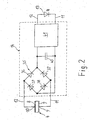
- FIG. 2 An example of the structure of the electronic circuit 14 is shown in FIG. 2 shown.
- An alternating current flows from the piezo converter 4 via the lines 11 and 12 into a rectifier circuit 35, which is formed by four rectifier diodes 36, 37, 38 and 39 is formed.
- a Storage capacitor 40 charged, the discharges of which each Pauses in actuation on the piezo converter 4 can be bridged.
- To one uniform current flow and thus a uniform brightness ensure the current flows through a constant current circuit or a Step-down DC-DC converter 41 to LED 13.
- the device according to the invention could not be shown here and use the described design variants for other purposes, for example instead of a bicycle dynamo.
- One by a wheel tire driven camshaft could then operate the lever 19.
- the Flashlight could also be a second, parallel piezo transducer have, whose actuating device compared to that of the first Piezowandlers is arranged rotated by 180 degrees, so that the two The hand lever is opposite and actuated when the hand is closed become.
- Two or more piezo transducers can also be used to increase the energy yield are connected in parallel, which act simultaneously with a periodically Pressure force can be applied.
- a rotating shaft is assigned with a cam for actuation, the drive of the shaft for example by a hand crank or a wheel tire of a bicycle can be done.
- the two or more parallel piezo transducers one after the other with a periodic acting pressure force can be applied.
Landscapes
- Engineering & Computer Science (AREA)
- Life Sciences & Earth Sciences (AREA)
- Sustainable Development (AREA)
- Sustainable Energy (AREA)
- General Engineering & Computer Science (AREA)
- General Electrical Machinery Utilizing Piezoelectricity, Electrostriction Or Magnetostriction (AREA)
- Charge And Discharge Circuits For Batteries Or The Like (AREA)
Abstract
Description
- Figur 1
- eine Taschenlampe als Gerät mit der erfindungsgemäßen Einrichtung zur Versorgung mit elektrischer Energie und
- Figur 2
- einen Schaltplan der Taschenlampe.
Claims (10)
- Einrichtung zur Versorgung tragbarer Geräte mit elektrischer Energie, dadurch gekennzeichnet, dass sie mindestens einen Piezowandler (4), bevorzugt ein Vielschichtelement, aufweist, der mit einer Vorrichtung (19, 22) verbunden ist, mit der er mit einer periodisch einwirkenden Druckkraft beaufschlagbar ist, dass dem Piezowandler (4) eine Gleichrichterschaltung (35) nachgeschaltet ist, in dem die durch die periodisch einwirkende Druckkraft an dem Piezowandler (4) abgreifbare periodische Spannung mit wechselndem Vorzeichen gleichgerichtet wird, dass der Gleichrichterschaltung (35) ein Speicherkondensator (40) nachgeschalteten ist, der über die Gleichrichterschaltung (35) aufladbar ist und dass durch den Ladungsabfluss aus dem Kondensator (40) über eine Konstantstromschaltung oder über einen Abwärts-DC-DC-Wandler (41) auch in den Pausen zwischen den Einwirkungen der Druckkraft auf den mindestens einen Piezowandler (4) ein kontinuierlicher und weitgehend gleichmäßiger Stromfluss gewährleistet ist.
- Einrichtung nach Anspruch 1, dadurch gekennzeichnet, dass die Vorrichtung zur Erzeugung der Druckkraft auf den Piezowandler (4) der Einrichtung (2) einen Hebel (19) aufweist, dass der Hebel (19) so angeordnet ist, dass beim Schwenken um seinen Gelenkpunkt (21) mittelbar oder unmittelbar eine Beaufschlagung der Stirnseite (29) des Piezowandlers (4) mit einer Druckkraft erfolgt.
- Einrichtung nach Anspruch 1 oder 2, dadurch gekennzeichnet, dass mindestens zwei Piezowandler parallel geschaltet sind.
- Einrichtung nach Anspruch 3, dadurch gekennzeichnet, dass die Piezowandler gleichzeitig mit einer periodisch einwirkenden Druckkraft beaufschlagbar sind.
- Einrichtung nach Anspruch 3, dadurch gekennzeichnet, dass die Piezowandler nacheinander mit einer periodisch einwirkenden Druckkraft beaufschlagbar sind.
- Einrichtung nach einem der Ansprüche 1 bis 5, dadurch gekennzeichnet, dass den Vorrichtungen (19, 22), mit denen der oder die Piezowandler (4) mit einer periodisch einwirkenden Druckkraft beaufschlagbar sind, eine rotierende Welle mit einem Nocken zur Betätigung zugeordnet ist.
- Einrichtung nach Anspruch 6, dadurch gekennzeichnet, dass auf der rotierenden Welle die Nocken so angeordnet sind, dass die Piezowandler gleichzeitig mit einer periodisch einwirkenden Druckkraft beaufschlagbar sind.
- Einrichtung nach einem der Ansprüche 6 oder 7, dadurch gekennzeichnet, dass die rotierende Welle zur Betätigung der Einrichtung (2) durch einen Radreifen angetrieben wird.
- Einrichtung nach einem der Ansprüche 1 bis 4, dadurch gekennzeichnet, dass die Einrichtung (2) in einer Lampe (1) eingebaut ist.
- Einrichtung nach Anspruch 9, dadurch gekennzeichnet, dass das Leuchtmittel der Lampe (1) eine oder mehrere Leuchtdioden (13) sind.
Applications Claiming Priority (2)
| Application Number | Priority Date | Filing Date | Title |
|---|---|---|---|
| DE10305026A DE10305026A1 (de) | 2003-02-07 | 2003-02-07 | Einrichtung zur Versorgung tragbarer Geräte mit elektrischer Energie |
| DE10305026 | 2003-02-07 |
Publications (2)
| Publication Number | Publication Date |
|---|---|
| EP1450478A2 true EP1450478A2 (de) | 2004-08-25 |
| EP1450478A3 EP1450478A3 (de) | 2005-06-22 |
Family
ID=32730860
Family Applications (1)
| Application Number | Title | Priority Date | Filing Date |
|---|---|---|---|
| EP04002076A Withdrawn EP1450478A3 (de) | 2003-02-07 | 2004-01-30 | Einrichtung zur Versorgung tragbarer Geräte mit elektrischer Energie |
Country Status (2)
| Country | Link |
|---|---|
| EP (1) | EP1450478A3 (de) |
| DE (1) | DE10305026A1 (de) |
Cited By (4)
| Publication number | Priority date | Publication date | Assignee | Title |
|---|---|---|---|---|
| CN101350577B (zh) * | 2007-07-20 | 2011-12-21 | 陈少宇 | 采用压电陶瓷发电的装置 |
| GB2451650B (en) * | 2007-08-07 | 2012-05-30 | Shakerscope Ltd | Multi Purpose Control Circuit |
| GB2486858A (en) * | 2012-04-18 | 2012-06-27 | Shakerscope Ltd | Multi-purpose control circuit |
| EP2501031A4 (de) * | 2009-11-11 | 2013-07-10 | Soundpower Corp | Elektrogerät mit energieerzeugungsfunktion |
Family Cites Families (14)
| Publication number | Priority date | Publication date | Assignee | Title |
|---|---|---|---|---|
| DE1212327B (de) * | 1963-09-21 | 1966-03-10 | Heinrich Maltner G M B H | Piezoelektrische Hochspannungs-Zuendvorrichtung, insbesondere fuer Feuerzeuge |
| US3808418A (en) * | 1973-04-02 | 1974-04-30 | A Conard | Light flashing apparatus |
| JPS5792702A (en) * | 1980-11-30 | 1982-06-09 | Eiichi Hirooka | Manually operated generating electric torch |
| DE3121254C2 (de) * | 1981-05-29 | 1987-04-23 | Horst 6531 Münster-Sarmsheim Klostermann | Handbetätigbares Gerät zur Erzeugung elektrischer Impulse für eine Anwendung am lebenden Körper |
| DE3546388A1 (de) * | 1985-12-31 | 1987-08-06 | Fraunhofer Ges Forschung | Druckluftbetriebener hochspannungsgenerator |
| JP2657617B2 (ja) * | 1992-11-27 | 1997-09-24 | 鈴木総業株式会社 | 発光部を具えた靴 |
| JPH0993911A (ja) * | 1995-09-28 | 1997-04-04 | Nec Kansai Ltd | Dc−dcコンバータ電源 |
| DE19601917A1 (de) * | 1996-01-15 | 1997-07-17 | Hartmann & Braun Ag | Anordnung zur Stromversorgung elektrischer Geräte mittels pneumatischer Energie |
| FR2745476B1 (fr) * | 1996-03-01 | 1998-04-03 | Thomson Csf | Semelles de chaussure a recuperation d'energie |
| DE29614851U1 (de) * | 1996-08-27 | 1996-11-21 | Kranz, Walter, 82024 Taufkirchen | Piezogenerator |
| DE19921055A1 (de) * | 1999-05-07 | 2000-11-16 | Fitz Herwig | Piezoelektrisch betriebene LED |
| DE19942739A1 (de) * | 1999-09-07 | 2001-03-08 | Michael Jensen | Wärmewandler |
| DE10021852A1 (de) * | 2000-05-05 | 2001-11-15 | David Finn | Energieversorgung für autonome Mikrosysteme |
| DE10025561A1 (de) * | 2000-05-24 | 2001-12-06 | Siemens Ag | Energieautarker Hochfrequenzsender |
-
2003
- 2003-02-07 DE DE10305026A patent/DE10305026A1/de not_active Withdrawn
-
2004
- 2004-01-30 EP EP04002076A patent/EP1450478A3/de not_active Withdrawn
Cited By (6)
| Publication number | Priority date | Publication date | Assignee | Title |
|---|---|---|---|---|
| CN101350577B (zh) * | 2007-07-20 | 2011-12-21 | 陈少宇 | 采用压电陶瓷发电的装置 |
| GB2451650B (en) * | 2007-08-07 | 2012-05-30 | Shakerscope Ltd | Multi Purpose Control Circuit |
| EP2501031A4 (de) * | 2009-11-11 | 2013-07-10 | Soundpower Corp | Elektrogerät mit energieerzeugungsfunktion |
| US8686620B2 (en) | 2009-11-11 | 2014-04-01 | Soundpower Corporation | Electric apparatus provided with power generating function |
| GB2486858A (en) * | 2012-04-18 | 2012-06-27 | Shakerscope Ltd | Multi-purpose control circuit |
| GB2486858B (en) * | 2012-04-18 | 2012-12-12 | Shakerscope Ltd | Multi-purpose control circuit |
Also Published As
| Publication number | Publication date |
|---|---|
| DE10305026A1 (de) | 2004-08-19 |
| EP1450478A3 (de) | 2005-06-22 |
Similar Documents
| Publication | Publication Date | Title |
|---|---|---|
| EP2280582A1 (de) | Leuchtdiodenbeleuchtung und deren Verfahren zur Stromsteuerung | |
| DE102005030123A1 (de) | Stromversorgungsanordnung und deren Verwendung | |
| DE202006020276U1 (de) | Manuell aufladbare Taschenlampe | |
| WO2001091521A1 (de) | Verkehrssignalanlage mit led-lichtquelle | |
| DE2908015C2 (de) | Gasfeuerzeug | |
| AR021149A1 (es) | Un sistema de energia para alimentar una carga variable | |
| DE102014114178A1 (de) | Stromversorgungsvorrichtung, Leuchte und Fahrzeug | |
| EP1450478A2 (de) | Einrichtung zur Versorgung tragbarer Geräte mit elektrischer Energie | |
| DE102017107993A1 (de) | Leistungsversorgungsvorrichtung und beleuchtungsvorrichtung | |
| DE102012100352B3 (de) | Treiberschaltung für Leuchtdioden | |
| DE102009044593A1 (de) | Betriebssteuergerät zum Betreiben eines Leuchtmittels | |
| DE102013213263B4 (de) | Stromrichter mit wenigstens einem elektrischen Energieverbraucher | |
| DE4420589A1 (de) | Fahrradbeleuchtung | |
| DE202010000188U1 (de) | LED-Lichterkettenvorrichtung mit einem Batteriekasten | |
| DE2804727C2 (de) | Elektrische Widerstands-Abbrennschweißmaschine | |
| DE19549853B4 (de) | Ansteuerungssystem zum Zünden bzw. Betreiben von Hochdruckentladungslampen | |
| DE112016001792T5 (de) | LED-Lampen-Treiber und Treiberverfahren mit besonders hohem Wirkungsgrad | |
| DE102009050661A1 (de) | Vorrichtung zum Erzeugung von Hilfsstrom durch eine Beleuchtungslampe | |
| DE10333418B4 (de) | LED-Taschenleuchte | |
| DE20313781U1 (de) | Elektrisch betreibbares, tragbares Gerät, insbesondere Taschenleuchte und Schaltung für ein derartiges Gerät | |
| DE102018216485A1 (de) | PV-Einrichtung mit verbesserter Gesamteffizienz | |
| DE202009012144U1 (de) | Vorrichtung zur Stromerzeugung durch Aufnahme von Licht durch einen Kristall | |
| DE2047152A1 (de) | Einrichtung zur Steuerung eines elek taschen Impuls oder Funkengenerators | |
| DE202017107199U1 (de) | LED-Leuchtröhre mit hohem Lichteffekt | |
| AT509609B1 (de) | Solarbetriebene led-leuchte |
Legal Events
| Date | Code | Title | Description |
|---|---|---|---|
| PUAI | Public reference made under article 153(3) epc to a published international application that has entered the european phase |
Free format text: ORIGINAL CODE: 0009012 |
|
| AK | Designated contracting states |
Kind code of ref document: A2 Designated state(s): AT BE BG CH CY CZ DE DK EE ES FI FR GB GR HU IE IT LI LU MC NL PT RO SE SI SK TR |
|
| AX | Request for extension of the european patent |
Extension state: AL LT LV MK |
|
| PUAL | Search report despatched |
Free format text: ORIGINAL CODE: 0009013 |
|
| AK | Designated contracting states |
Kind code of ref document: A3 Designated state(s): AT BE BG CH CY CZ DE DK EE ES FI FR GB GR HU IE IT LI LU MC NL PT RO SE SI SK TR |
|
| AX | Request for extension of the european patent |
Extension state: AL LT LV MK |
|
| 17P | Request for examination filed |
Effective date: 20051222 |
|
| AKX | Designation fees paid |
Designated state(s): AT BE BG CH CY CZ DE DK EE ES FI FR GB GR HU IE IT LI LU MC NL PT RO SE SI SK TR |
|
| 17Q | First examination report despatched |
Effective date: 20060125 |
|
| STAA | Information on the status of an ep patent application or granted ep patent |
Free format text: STATUS: THE APPLICATION IS DEEMED TO BE WITHDRAWN |
|
| 18D | Application deemed to be withdrawn |
Effective date: 20071030 |